When you click on links to various merchants on this site and make a purchase, this can result in this site earning a commission. Affiliate programs and affiliations include, but are not limited to, the eBay Partner Network.
To share the conversation publicly, here are the highlights of email with Tuomo:
Critical 928 related dimensions:
Cross-sectional area of the port at the sealing surface of the head - 1867.84mm^2
Cross-sectional area of the port at the sealing surface of the manifold (excluding injector bung)- 1688.67mm^2
Common material dimension:
2"OD-1.75"ID RMR extruded tube internal cross-sectional area - 1551.79mm^2
2"OD-16guage (1.87" ID) internal cross-sectional area - 1771.9mm^2
2.25"OD-2"ID RMR extruded tube internal cross-sectional area - 2026.83mm^2
2.25"OD-11guage (2.1" ID) internal cross-sectional area - 2047.15mm^2
My vote is for the 2.25" 11g tubing, as you can use it in mandrel bent form or use the 2.25"OD-2"ID extrusions from Ross Machine Racing depending on your application. The thicker wall will be much easier to weld to the flange without blowing through for those assembling manifolds at home. The 2"-16g is probably the optimal selection all things considered, but it could be a pain to work with.
Thoughts?
Hans
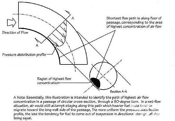
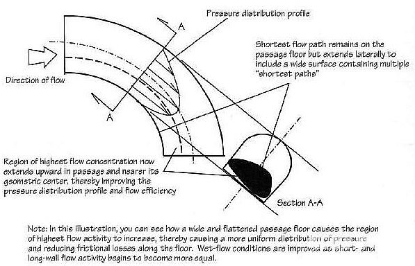
Air flowing into the engine is happier seeing a shrinking cross-sectional area than an expanding one. The pipe area can shrink relatively rapidly and air will still be happy. Air will however become very unhappy if it has to rapidly slow down because the cross-sectional area increases. So unhappy that it will throw a turbulence tantrum.
Taking out the space for injector and fuel spray, the stock S4 port is about 1700 mm^2 in round numbers. To keep air happy, you definitely don't want the runner smaller than the port. But you don't want it much larger than that either, given that the port is pretty large for the air that most of us are asking it to flow. Pipemax, for example, wants a lot smaller port for a 100% VE 5.0L engine at 7000 rpm. Most people aren't going to increase displacement to 7L, get the VE to 120%+, or spin the engine past 7500 rpm. This tells me that we want a runner that is slightly larger than that 1700 mm^2, but only slightly.
2.25 OD and 2" ID runner has area of 2027 mm^2. That's about 19% more than the port. That's a lot.
2.0 OD and 1.75" ID runner has area of 1552 mm^2. That's about 9% less than the port. That's not going to keep air happy without epoxying or welding the intake port in the head smaller.
Pipemax calls for much smaller runners. But there's no way to make them smaller without causing problems with stock S4 heads. So 1.75 ID is out of question and 2 ID is a bit big.
1.87" ID or something like that would probably be the best. That would give 1772 mm^2 and about 5% more area than the port. This is about as close to the Goldilocks situation as we can hope for.
Now, how should we get to that 1.87" ID? We can go with a thinner wall 2" OD pipe or thicker wall 2.25" OD pipe. My vote goes to the thinner wall 2" OD pipe, for the following reasons:
Both pipes have burst strength that is way above anything that they'll see in this application.
A big advantage of the 2" OD pipe is that there's a better chance of getting a cross-ram manifold done. Compare seven times the runner width to three times the bore spacing. 2"x7 = 14" whereas 2.25"x7=15.75". The available space with 122mm bore spacing is 14.4". 2" fits while 2.25" won't. It still wont be easy even with 2" pipe. [Edit: this computation is wrong because it ignores the 25mm bore offset. 2.25" would fit in principle. It won't in practice because of water bridge, the top cross brace, and the air box.]
Also, 2"-16g (1.87" ID) tube has about 47.5mm ID, right? Can we find out whether the Weber or Dellorto 48mm velocity stacks match with that? Because if they do, the knock-off velocity stacks are available for one third of the price that Ross Machine Racing is asking for their velocity stacks.
The final advantage is that if someone wants to throw bigger money at this and fabricate tapered runners, then one is definitely better of starting with a smaller ID at the port end.
I will source some 50mm velocity stack options for those who need them, or whip up a design to aid in fabrication and have them quoted so that option will be available.
Can we get another two solid commitments to get his project rolling? I will collect funds Friday afternoon.
Looks like we are at four confirmed, we just need one more solid commitment. That said, if we get more than 5, the price may drop. I have asked the shop to quote at 10 sets (just in case).
Also, please let me know if anyone wants matching fuel rails.
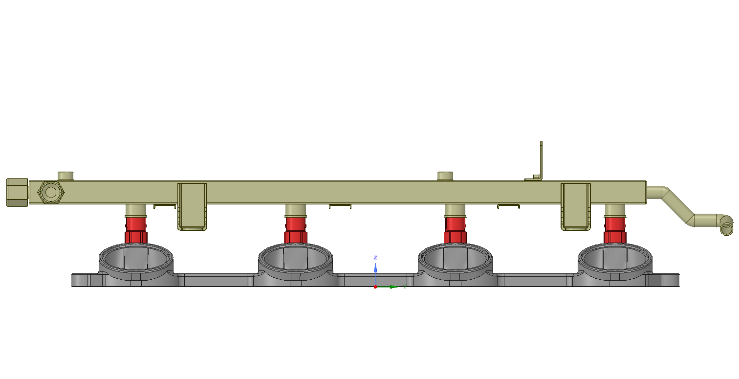
I have been working on the redesign to fit in the 1.5x3" bar stock to keep the the quoted price at the low volume. As part of the exercise, I inserted the passenger side stock fuel rail into the design to see how it would fit. As the pictures show, the stock mounting tabs will interfere with most runner designs. Stock rails will require custom mounts, and removal of the original tabs.
I can design custom mounts if people would like them to use the stock rail, but even then the original plastic covers may provide additional clearance issues. I can also provide custom fuel rails and mounts. We will just need to have some consensus to get enough pieces to keep the fuel rail parts a reasonable price.
Also, while I am working on it, is everyone alright with converting from studs to machine-screws? I think a nice M8 capscrew with corresponding countersunk relief on the flange would be considerably cleaner.
In my opinion, the stock fuel rails are great. They are designed for batch fuel injection and work well with that, as long as there are enough dampers in the system. I am of the philosophy that one should not replace stock components unless there's a really good reason to do so. Furthermore, when changing one component to aftermarket component, it's better to try to make it work with as many stock components as possible, as long as performance isn't sacrificed in a meaningful way.
To that effect: Hans, can you show a straight 2" OD runner going up from the flange with the stock fuel rail attached to it? How much interference is there? If it's just a tiny bit, I'd be fine just cutting a corner off that fuel rail tab and be done with it. If it's more, then let's see how we can reuse the stock fuel rails with the minimum effort.
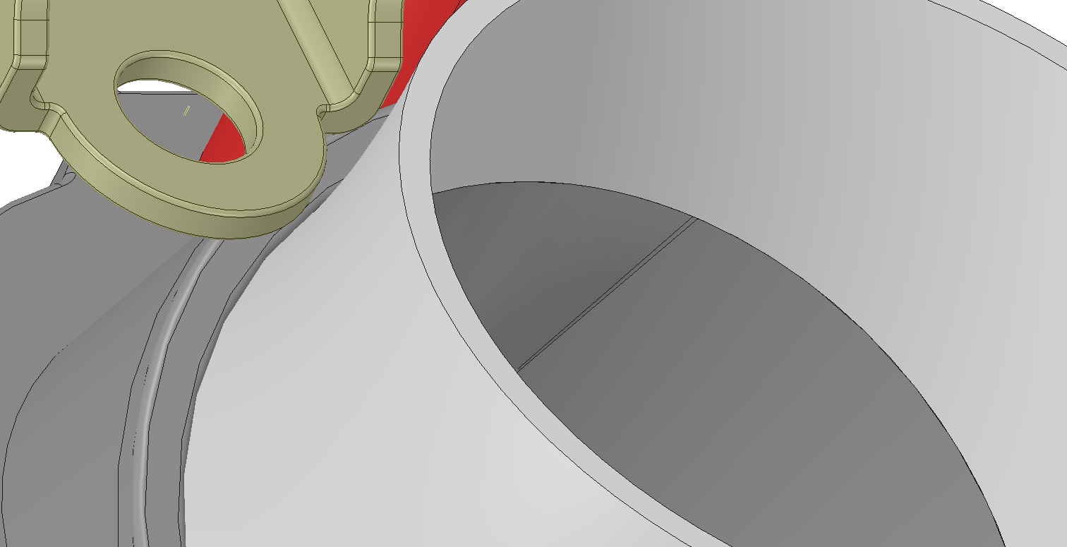
It barely clears the bent runner, but you can see that the requisite mounting hole would be interfering with the base of the runner.
The offset is different between the front and rear mounts, so its not something I am willing to machine (or better yet something people are willing to pay for). As there would be fixturing fees for four different parts.
I can provide dimensions for those who would want to make a custom bracket to mount a stock rail.
It's a custom manifold. Custom things will be done for fueling, from cutting off the rail end for an an fitting, to cutting the mountings off to make them work at whatever height the injectors will be at.
I had a bit more free time today than expected, so knocked out the redesign.
I am going to separate into two sets of images. One showing the flange with a stock fuel rail (modifications will be required to the rail, or custom mounts made). The second post will show a -8AN fuel rail option.
I will print a test file tomorrow at the office, confirm everything looks good, and will get the file off to the machine shop.
Here are download links for 3D PDF models if you want a closer look:
How about fuel rail installation angle, has anyone checked whether the stock rails should be turned the way that fuel will be sprayed deeper to intake port?
Somehow I have a feeling that specially with multi-hole injectors, the fuel is sprayed too much towards the floor just before port divider.
It could be that I remember wrong and there is always possibility of cutting little more from stock fuel rail tab and make the holes oval to adjust them a bit.
Anyways, this is important thing for patch injection as first set of fuel should be sprayed against intake valve where the hot valve will vaporize the fuel before valve opens.


 12-30-2014, 08:25 PM