

928 inventors!

 09-18-2012, 09:41 PM
#32
Instructor
Join Date: Sep 2012
Location: Philadelphia, PA
Posts: 115
Likes: 0
Received 0 Likes
on
0 Posts
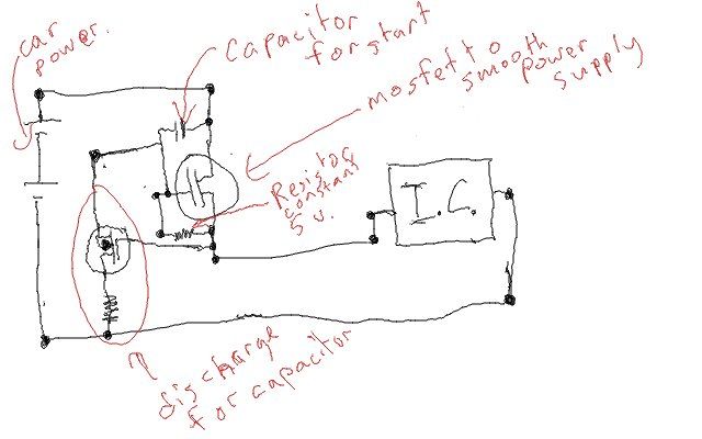
yes exactly. something that would only allow 5v to pass. actually a large enhancement mosfet transistor with the correct ohm rating resistor between the drain and gate would keep it closed (its counterintuitive, but that means on), but the resistor would not close it in the first place. so a capacitor between the source and the gate which will turn it on and allow flow through it so that the resistor will keep it open at 5v, but the capacitor will then stop DC voltage over its self (but ac will go through it, put a diode infront of it all, but I dont expect there would be any of that in the first place) through its self as it reaches charge so that a surge can not reach the IC. at which point it will turn on once but never again, so it needs a discharger that will discharge it only after the power to the car has been turned off. a depletion mosfet with source and drain on series with the capacitor and a resistor.
Here is a schematic of what it should look like:
 .
.
each of the inputs for the turn light, break light, and running light, will need a regulator on them. so here is what the entire thing should look like, including a few LED's, but there could be more or less of those. here it is:
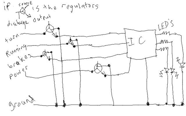
the only issue now is housing, coding, and choosing which components to use. but atleast there is a concept down now.
EDIT: I missed a few posts while typing this up. Ohm's law is that current = Volts/resistance. putting just and IC and a Led on a battery might not provide enough resistance and the battery will think it is shorting, and It will over heat and bad things will happen and you will need a new battery, IC, leds and altoids box (or car if you are at that point) and a fire extinguisher. to prevent said bad things you need a few resistors.
Here is a schematic of what it should look like:
.each of the inputs for the turn light, break light, and running light, will need a regulator on them. so here is what the entire thing should look like, including a few LED's, but there could be more or less of those. here it is:
the only issue now is housing, coding, and choosing which components to use. but atleast there is a concept down now.
EDIT: I missed a few posts while typing this up. Ohm's law is that current = Volts/resistance. putting just and IC and a Led on a battery might not provide enough resistance and the battery will think it is shorting, and It will over heat and bad things will happen and you will need a new battery, IC, leds and altoids box (or car if you are at that point) and a fire extinguisher. to prevent said bad things you need a few resistors.
 09-18-2012, 10:02 PM
#34
Banned

 09-18-2012, 10:37 PM
#35
Drifting
yes exactly. something that would only allow 5v to pass. actually a large enhancement mosfet transistor with the correct ohm rating resistor between the drain and gate would keep it closed (its counterintuitive, but that means on), but the resistor would not close it in the first place. so a capacitor between the source and the gate which will turn it on and allow flow through it so that the resistor will keep it open at 5v, but the capacitor will then stop DC voltage over its self (but ac will go through it, put a diode infront of it all, but I dont expect there would be any of that in the first place) through its self as it reaches charge so that a surge can not reach the IC. at which point it will turn on once but never again, so it needs a discharger that will discharge it only after the power to the car has been turned off. a depletion mosfet with source and drain on series with the capacitor and a resistor.
Here is a schematic of what it should look like:
.
each of the inputs for the turn light, break light, and running light, will need a regulator on them. so here is what the entire thing should look like, including a few LED's, but there could be more or less of those. here it is:
the only issue now is housing, coding, and choosing which components to use. but atleast there is a concept down now.
EDIT: I missed a few posts while typing this up. Ohm's law is that current = Volts/resistance. putting just and IC and a Led on a battery might not provide enough resistance and the battery will think it is shorting, and It will over heat and bad things will happen and you will need a new battery, IC, leds and altoids box (or car if you are at that point) and a fire extinguisher. to prevent said bad things you need a few resistors.
Here is a schematic of what it should look like:
.each of the inputs for the turn light, break light, and running light, will need a regulator on them. so here is what the entire thing should look like, including a few LED's, but there could be more or less of those. here it is:
the only issue now is housing, coding, and choosing which components to use. but atleast there is a concept down now.
EDIT: I missed a few posts while typing this up. Ohm's law is that current = Volts/resistance. putting just and IC and a Led on a battery might not provide enough resistance and the battery will think it is shorting, and It will over heat and bad things will happen and you will need a new battery, IC, leds and altoids box (or car if you are at that point) and a fire extinguisher. to prevent said bad things you need a few resistors.
Not sure what the plans were for incorporating ICs... maybe some sort of sequencer or something... presuming IC = integrated circuit. Mosfets, J-fets, PN junctions, integrated, discrete semiconductors are all things I used to know fairly well.
Anyhow, sounds like you have a cool creative concept ready to breadboard.
09-18-2012, 11:05 PM
#37
Instructor
Join Date: Sep 2012
Location: Philadelphia, PA
Posts: 115
Likes: 0
Received 0 Likes
on
0 Posts
@G8RB8. a zener diode could not work, because aswell as a power source, the circuit is designed to prevent surges from dammaging the IC. the Zener diode will allow reverse flow if above if the voltage is high enough. if we put a backwards one into the circuit, it will let 11 or 12 volts flow to the IC, which will fry it and be very bad, and if there were a surge, the backwards zener diode would just allow the surge to pass through it. the mosfet circuit I drew up is based on a circuit that I use in airsoft guns to protect the motor from a power surge, and provide a constant voltage. in this case it will provide me with a constant 5v and turn a surge into heat instead of just letting it kill the IC., but actually that reminds me that I will need a heat sink for this, so thanks for the input.
also i realized that on the start of the regulator circuit, 11 volts and declining will hit the IC until it reaches 5v, so I should put a resistors between the capacitor and the enhancment mosfet, to prevent that.
also i realized that on the start of the regulator circuit, 11 volts and declining will hit the IC until it reaches 5v, so I should put a resistors between the capacitor and the enhancment mosfet, to prevent that.
09-18-2012, 11:10 PM
#38

Timbuktoo, you are going to fit right in around here.
/thumbs up.
/thumbs up.
09-18-2012, 11:11 PM
#39
Rennlist Member
not quite electrical wiz. I'm more acquainted with computer programming (not much though, I know a little bit, but am taking JAVA in school this year), and lesser mechanicals (airsoft gearboxes, not nearly as complicated as a v8). my dad is really good with electrical engineering, he did make sure I know what all the basic components do and how to use a multimeter and soldering iron. I realized though that we would need to run wires up front to power the IC's, because I dont think that we would be able to let them just run off the existing lights because it is soo intermittent.
another thing that it would need is somesort of power supply and surge protection that will not shut off if it surges, but only limit the power surge, because IC's normally run off 5v (car's normal output is like 11 or 12 according to the volt meter on the dash, IDK how reliable it is) and will fry with more than 15v. but the car probably has such a power supply for the ECU, or the ECU is made with more resilliant components, which we could do for the lights circuit.
another thing that it would need is somesort of power supply and surge protection that will not shut off if it surges, but only limit the power surge, because IC's normally run off 5v (car's normal output is like 11 or 12 according to the volt meter on the dash, IDK how reliable it is) and will fry with more than 15v. but the car probably has such a power supply for the ECU, or the ECU is made with more resilliant components, which we could do for the lights circuit.
Battery voltage is anywhere from 12.0 (engine off, mostly discharged) to 14.2 (engine running, mostly charged). So yes, the 928's voltage gauge is usually a tad inaccurate.
 09-18-2012, 11:16 PM
#40
Rennlist Member
@G8RB8. a zener diode could not work, because aswell as a power source, the circuit is designed to prevent surges from dammaging the IC. the Zener diode will allow reverse flow if above if the voltage is high enough. if we put a backwards one into the circuit, it will let 11 or 12 volts flow to the IC, which will fry it and be very bad, and if there were a surge, the backwards zener diode would just allow the surge to pass through it.
...
...
Like this:

The trick is to always have some current flowing through the zener (i3), so select a resistor so that the input current (from 12v to 5v) is always greater (by a good margin) than what the IC needs. As the battery voltage rises (including spikes and surges) the zener just shunts more current to ground, until it reaches its thermal capacity and turns into smoke.
Last edited by jcorenman; 09-18-2012 at 11:26 PM. Reason: add pic
09-18-2012, 11:18 PM
#41
That's what they're designed to do. They are purposely reverse biased and maintain a constant voltage drop across the junction once the break down voltage is reached. You need one with a breakdown voltage of five volts or use a voltage divider to get you five volts. Resistors won't work without complex feedback loops due to the highly variable voltage in a car. You can expect your circuit to see anywhere from ~8 - 16 V.
From a quick Google. Change the zener to a 5V and everything else should be OK OR...
http://schematic-audio.blogspot.com/...oda-zener.html
From a quick Google. Change the zener to a 5V and everything else should be OK OR...
http://schematic-audio.blogspot.com/...oda-zener.html
09-18-2012, 11:22 PM
#42
Actually a zener would work, but don't it in series with the supply to your chip. Instead, feed current with a resistor and then use the zener as a shunt to ground. Connect your load (the chip that needs 5.0v) across the zener. This was popular before IC voltage regulators got invented.
09-19-2012, 12:09 AM
#43
Instructor
Join Date: Sep 2012
Location: Philadelphia, PA
Posts: 115
Likes: 0
Received 0 Likes
on
0 Posts
i didnt realize that the zener would be in paralell, that actually makes a lot more sense then doing the mosfet with the resistor, because becase it will keep it more exactly at 5v, and it saves me some math finding out what resistors and capacitors and mosfets I will need.
as for the IC, I was thinking of putting microprocessor with a small amount of solid state which I would put a bit of code onto, that way it would be reprogrammable, and I could change the LED scheme if I ever was inclined to do so (or if a cop or someone said the LED's were too distracting, I dont know if there are any regulations about that)
also, when I put the zener shunt regulator thing in, do I need to do it with the capacitors and transistor, or can it be with only the 1 resistor and 1 zener diode, because both have been suggested, and it would be a little bit easier to put the second option in.
09-19-2012, 12:09 AM
#44
Banned
Sorry, I must have dozed off.
What patterns are we trying to make?
What lights on the 928?
What LED's on what panel?
What are the IC's for?
What lights on the 928?
What LED's on what panel?
What are the IC's for?
09-19-2012, 12:14 AM
#45
The caps are for noise and the transistor is for power. You'll have to determine your tolerance for the former and requirement for the later.
I assume this means you want to build it yourself from discreet components then?
I assume this means you want to build it yourself from discreet components then?