


Center Console Lighting Problem: Blowing Fuse
Electron Wrangler
Lifetime Rennlist
Member
Lifetime Rennlist
Member

Joined: Mar 2002
Posts: 13,665
Likes: 621
From: Phoenix AZ
When you measure the resistance between 58 & 31 on the connector side - you are seeing the cold resistance of all the illumination filaments - this will be a very low ohms value... normal.
You have all the pod illumination bulbs and the variable lights in the console - probably 10 + bulbs at ~2W each, so resistance is likely <1 ohm (cold). Filament resistance varies by a factor of 10 or so between cold & hot (with hot being the spec point and the high value)
You can make this less by removing the rheostat - should approximately double the resistance - if so its all likely OK.
Alan
Thread Starter
Pro

Joined: May 2008
Posts: 591
Likes: 2
From: Charlotte, NC
OK. I was measuring resistance at the potentiometer connector (with the potentiometer removed) with the red lead of the ohmmeter in the potentiometer connector and the black lead to ground. With the defroster switch removed I measured 12.5ohms. I was then bridging connectors 58 and 31 and the resistance dropped to 0.5ohms--not sure if that tells us anything or not.
With the potentiometer installed, if I use the ohmmeter to bridge contacts 58 and 31, I get 2.2ohms with the potentiometer all the way in one direction, and 5ohms with the potentiometer turned all the way in the other direction. Seems about what you would have predicted.
With the potentiometer installed, if I use the ohmmeter to bridge contacts 58 and 31, I get 2.2ohms with the potentiometer all the way in one direction, and 5ohms with the potentiometer turned all the way in the other direction. Seems about what you would have predicted.
Electron Wrangler
Lifetime Rennlist
Member
Lifetime Rennlist
Member
Joined: Mar 2002
Posts: 13,665
Likes: 621
From: Phoenix AZ
Why are you bridging 31 and 58?
31 is ground and 58 the illumination circuit - i.e you are shorting it to ground
I see no reason to ever do this? Between 58 and 31 is where the bulb goes for the switch illumination that's all.
Alan
31 is ground and 58 the illumination circuit - i.e you are shorting it to ground
I see no reason to ever do this? Between 58 and 31 is where the bulb goes for the switch illumination that's all.
Alan
Thread Starter
Pro
Joined: May 2008
Posts: 591
Likes: 2
From: Charlotte, NC
Yeah. I'm very much a novice at electrics. My thought was if I bridge 58 and 31 I would simulate a bulb being there and then I could measure resistance at the potentiometer and see if there's a short somewhere else in the circuit. I'm guessing from your reply that it doesn't work that way.
Thread Starter
Pro
Joined: May 2008
Posts: 591
Likes: 2
From: Charlotte, NC
Any suggestions on where to go from here? At this point all I know is that with the defroster switch removed, the fuse doesn't blow and the HVAC lighting works; with a brand new defroster switch installed, the fuse blows whether the defroster relay is pulled or not. Did you see the picture of the connector at the end of page 4? Would the mangled connectors at 58 and 31 possibly cause the short?
Addict
Rennlist Member
Rennlist Member
Joined: Jul 2001
Posts: 7,333
Likes: 117
From: Shawnee, KS, USA
Manfred, I'm glad you referenced your post #59; that's a huge help and might be the little hint I needed. I missed that post the first time around.
Those two smaller center terminals are terminal 31 and 58 (I wasn't completely sure because it's hard to see one of the terminal designations in the photo so I went out and pulled mine and took a look).
And... those are the two terminals that, if shorted, will lead to the trouble you've been seeing.
Here's my best guess at this point. I believe there's a good chance that the contacts in the connector (socket/receptacle) are shorted (perhaps intermittently, like when they're under pressure from the switch being plugged in) at the back where the wires are crimped into them; one or both of them—as mangled as they appear—might also be pushed back into the connector and therefore no longer properly separated from each other.
If you can get them out, there's a chance you can bend them back into the proper shape and push them back in and get everything working again. If they're too far gone, you can probably find replacement contacts and crimp them onto the wires.
Typically, these contacts can be released by inserting a tool at the front and then pulled out from the back. The trick is to push a very small-bladed flat-tip screwdriver (jeweler's screwdriver or whatever; there are actually release tools, but you can usually substitute more commonly-available tools) alongside one of the sides of the contact. There will be a bent springy retaining tab (a.k.a. "retention clip") on the contact that keeps it from moving back in the connector. If you flatten that out while simultaneously pulling the crimped-on wire from the back, the contact will be released and will pull out. Hard to describe; I'll see if I can dig up a photo and/or procedure somewhere. On one of the larger contacts (the diagonally positioned one really close to the edge), you can actually easily see the retaining tab from the side. Each of of the contacts will have such a tab.
The side of the contact where you need to to push in a tool from the front is obvious on the larger contacts; it's the side with the semicircle that accommodates a release tool. It's not quite so obvious on the smaller contacts that you need to release. I might be seeing the little retaining tabs on the right side of both of them in your photo, but I'm not sure. It looks like a paper clip might actually serve as a workable release tool for them.
I'd recommend removing and working on them one at a time so there's no chance that you accidentally get them swapped around.
Edit: I can't quickly find a good diagram/procedure, but here's a drawing that should give you the general idea of what a typical contact looks like (and note in particular the bent-out retainer tab/clip to the right of the dotted-line box):
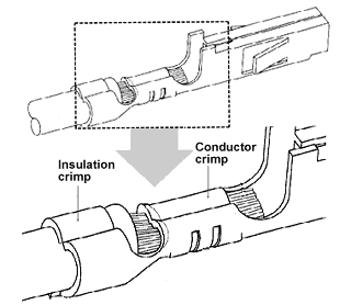
Many connectors (probably most of them in our cars) have terminals that are some variation of this that are releasable. It's nice (and sometimes necessary) to have the proper release tools for them, but the simpler ones like the one in question here can typically be released with tools you're likely to have on hand.
Those two smaller center terminals are terminal 31 and 58 (I wasn't completely sure because it's hard to see one of the terminal designations in the photo so I went out and pulled mine and took a look).
And... those are the two terminals that, if shorted, will lead to the trouble you've been seeing.
Here's my best guess at this point. I believe there's a good chance that the contacts in the connector (socket/receptacle) are shorted (perhaps intermittently, like when they're under pressure from the switch being plugged in) at the back where the wires are crimped into them; one or both of them—as mangled as they appear—might also be pushed back into the connector and therefore no longer properly separated from each other.
If you can get them out, there's a chance you can bend them back into the proper shape and push them back in and get everything working again. If they're too far gone, you can probably find replacement contacts and crimp them onto the wires.
Typically, these contacts can be released by inserting a tool at the front and then pulled out from the back. The trick is to push a very small-bladed flat-tip screwdriver (jeweler's screwdriver or whatever; there are actually release tools, but you can usually substitute more commonly-available tools) alongside one of the sides of the contact. There will be a bent springy retaining tab (a.k.a. "retention clip") on the contact that keeps it from moving back in the connector. If you flatten that out while simultaneously pulling the crimped-on wire from the back, the contact will be released and will pull out. Hard to describe; I'll see if I can dig up a photo and/or procedure somewhere. On one of the larger contacts (the diagonally positioned one really close to the edge), you can actually easily see the retaining tab from the side. Each of of the contacts will have such a tab.
The side of the contact where you need to to push in a tool from the front is obvious on the larger contacts; it's the side with the semicircle that accommodates a release tool. It's not quite so obvious on the smaller contacts that you need to release. I might be seeing the little retaining tabs on the right side of both of them in your photo, but I'm not sure. It looks like a paper clip might actually serve as a workable release tool for them.
I'd recommend removing and working on them one at a time so there's no chance that you accidentally get them swapped around.
Edit: I can't quickly find a good diagram/procedure, but here's a drawing that should give you the general idea of what a typical contact looks like (and note in particular the bent-out retainer tab/clip to the right of the dotted-line box):
Many connectors (probably most of them in our cars) have terminals that are some variation of this that are releasable. It's nice (and sometimes necessary) to have the proper release tools for them, but the simpler ones like the one in question here can typically be released with tools you're likely to have on hand.
Last edited by Ed Scherer; Mar 2, 2013 at 10:12 PM.
Thread Starter
Pro
Joined: May 2008
Posts: 591
Likes: 2
From: Charlotte, NC
Manfred, I'm glad you referenced your post #59; that's a huge help and might be the little hint I needed. I missed that post the first time around.
Those two smaller center terminals are terminal 31 and 58 (I wasn't completely sure because it's hard to see one of the terminal designations in the photo so I went out and pulled mine and took a look).
And... those are the two terminals that, if shorted, will lead to the trouble you've been seeing.
Here's my best guess at this point. I believe there's a good chance that the contacts in the socket are shorted (perhaps intermittently, like when they're under pressure from the switch being plugged in) at the back where the wires are crimped into them; one or both of them�as mangled as they appear�might also be pushed back into the socket and therefore no longer properly separated from each other.
If you can get them out, there's a chance you can bend them back into the proper shape and push them back in and get everything working again. If they're too far gone, you can probably find replacement contacts and crimp them onto the wires.
Typically, these terminals can be released and pushed-from-the-front/pulled-from-the-back. The trick is to push a very small-bladed flat-tip screwdriver (jeweler's screwdriver or whatever) alongside one of the sides of the contact. There will be a bent springy retaining tab on the contact that keeps it from moving back in the socket. If you flatten that out while simultaneously pulling the connected wire from the back, the contact will be released and will pull out. Hard to describe; I'll see if I can dig up a photo and/or procedure somewhere. On one of the larger contacts (the diagonally positioned one really close to the edge), you can actually easily see the retaining tab from the side. Each of of the contacts will have such a tab.
The side of the contact where you need to to push in a tool from the front is obvious on the larger contacts; it's the side with the semicircle that accommodates a release tool. It's not quite so obvious on the smaller contacts that you need to release. I might be seeing the little retaining tabs on the right side of both of them in your photo, but I'm not sure. It looks like a paper clip might actually serve as a workable release tool for them.
I'd recommend removing and working on them one at a time so there's no chance that you accidentally get them swapped around.
I'd recommend removing and working on them one at a time so there's no chance that you accidentally get them swapped around.
intermittently, like when they're under pressure from the switch being plugged in
It's too late tonight to get after it but I'll get those wires pulled out one way or another tomorrow.
Addict
Rennlist Member
Rennlist Member
Joined: Jul 2001
Posts: 7,333
Likes: 117
From: Shawnee, KS, USA
BTW... I've had some minor problems here and there with similar contacts in the past. It's a good idea after unplugging one of these switches (or even the bulbs in them) to shine a flashlight in and inspect the condition of the contacts. If they're a little deformed, you can usually bend them back into shape well enough from the front (little screwdrivers are handy for this) such that no further repair is necessary. But... if you don't notice in time and try to force the switch/bulb/whatever back in when re-plugging, you can do some serious enough bending that it will be much harder to repair.
Main things to look for: (1) bent contacts, and (2) contacts that are pushed back into the connector because their retention tab/clip has failed or become deformed. (2) has been reported a number of times by people on the central electric panel in the 928s because the relay contacts are so damn tight and sometimes corroded.
So... always inspect before re-plugging.
Rennlist Stories
The Best Porsche Posts for Porsche Enthusiasts

Genius Porsche-Themed Gifts That'll Make Any Dad or Grad Smile
Joe Kucinski
10 Used Porsches Are Selling for Way Too Cheap
Joe Kucinski
Tuner Is Converting Porsche 911s Into Shooting Brakes
Verdad Gallardo
This Coachbuilt Creation Is A Modern Take on the Legendary Porsche 917
Verdad Gallardo
Is This Convertible Cayenne A Steal, Or A Returnless Investment?
Verdad Gallardo
10 Best Non-Flat Six Porsches You Can Buy For Under $100K
Joe Kucinski
Porsche's Top 5 Most Questionable Naming Decisions
Verdad Gallardo
Pogea Racing's 964 Porsche 911 Reimagination Stands Out in a Crowded Field
Verdad Gallardo
6 Convertible Top MYTHS Most People Don't Understand!
Michael S. Palmer
Thread Starter
Pro
Joined: May 2008
Posts: 591
Likes: 2
From: Charlotte, NC
Ok, well the news isn't good I don't think.
I was able to pull out all the connectors other than 31 (two grounds feed one connector). I was able to remove 58 (Bk/Bl) so I know that 58 and 31 are not touching each other inside the connector.
I then hooked up the Bk/Bl wire to post 58 on the defroster switch and then ran a wire from 31 on the connector to 31 on the defroster switch while measuring the resistance at the potentiometer. The resistance fell from 12.5ohms to 0.5ohms as soon as I make the connection.
I think that means I have to trace that Bk/bl wire to where it goes next? and see where it's shorting out? It goes into a massive wire loom behind the pod fairly quickly. Anyone know where it reappears?
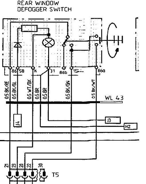
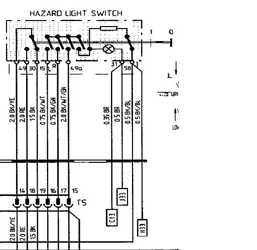
I looked at the wiring diagram and it doesn't make sense to me. From the defroster the diagram says the Bk/Bl wire goes from H33 to J4. If I go to J4 and find the H33 lead (Bk/Bl) it simply leads to the Hazard switch (but I know from looking behind the pod that the wire goes into a loom and doesn't simply daisy chain over to the hazard switch):
I'm thinking the next test (before I start trying to follow the Bk/Bl defroster lead) is to plug in the defroster switch and take out the hazard switch and see if I get the same results (i.e. no drop in resistance with defroster switch plugged in and the hazard switch out; plug in the hazard switch and watch the resistance drop).
I was able to pull out all the connectors other than 31 (two grounds feed one connector). I was able to remove 58 (Bk/Bl) so I know that 58 and 31 are not touching each other inside the connector.
I then hooked up the Bk/Bl wire to post 58 on the defroster switch and then ran a wire from 31 on the connector to 31 on the defroster switch while measuring the resistance at the potentiometer. The resistance fell from 12.5ohms to 0.5ohms as soon as I make the connection.
I think that means I have to trace that Bk/bl wire to where it goes next? and see where it's shorting out? It goes into a massive wire loom behind the pod fairly quickly. Anyone know where it reappears?
I looked at the wiring diagram and it doesn't make sense to me. From the defroster the diagram says the Bk/Bl wire goes from H33 to J4. If I go to J4 and find the H33 lead (Bk/Bl) it simply leads to the Hazard switch (but I know from looking behind the pod that the wire goes into a loom and doesn't simply daisy chain over to the hazard switch):
I'm thinking the next test (before I start trying to follow the Bk/Bl defroster lead) is to plug in the defroster switch and take out the hazard switch and see if I get the same results (i.e. no drop in resistance with defroster switch plugged in and the hazard switch out; plug in the hazard switch and watch the resistance drop).
Addict
Rennlist Member
Rennlist Member
Joined: Jul 2001
Posts: 7,333
Likes: 117
From: Shawnee, KS, USA
This isn't making a whole lot of sense. IIRC, you've tried two different defroster switches, right?
What you're describing now sounds like a short across the bulb in the defroster switch. Remember your post #54? There was a clear indication of a short in the switch right there.
I think I want to revisit testing of the switch itself. I just pulled mine again and replaced the LED that was in it with what I believe is the correct incandescent bulb. I'm going to test across various terminals and provide the resistances I see. Give me a few minutes... I'll update this post with the numbers.
with bulb installed in switch:
31 / K : 16 Ω (resistance of incandescent bulb with cold filament)
31 / 58 : can't test reliably: see note 2
31 to any terminals other than 31 and 58: ∞ Ω
with bulb removed from switch:
31 / K : ∞ Ω (note: with bulb removed, this is an open circuit)
31 / 58: can't test reliably: see note 2
31 to any terminals other than 31 and 58: ∞ Ω
Notes:
- Jiggling the bulb in the socket can affect the resistance a little due to resistance at the bulb-leads-to-socket-contacts point.
- Due to the presence of a diode in the 58-to-31 or 58-to-K paths, resistance tests using a DMM will be highly dependent on the DMM's testing voltage. The DMM I use (Fluke 189) intentionally keeps testing voltages low. Consequently, it won't exceed the breakdown voltage of the diode and thus yields a very high resistance (not infinite, though, due to a little leakage current throught the diode). The results of such tests are largely useless with respect to the problem at hand.
- As you can tell from the digram, 31, 58, and K shouldn't have anything to do with any other terminals.
Last edited by Ed Scherer; Mar 3, 2013 at 01:02 PM.
Thread Starter
Pro
Joined: May 2008
Posts: 591
Likes: 2
From: Charlotte, NC
Hi Ed. Yes, I bought a new defroster switch (with bulb preinstalled) and it did not correct the problem. I'm wondering if I was misled by the fact that the defroster switch was the last switch installed--as if the circuit with the short is not complete unless all the pod switches are installed so whichever is the last switch installed is when the resistance will drop.
Thanks for going through the trouble of pulling your car apart to help me out.
Thanks for going through the trouble of pulling your car apart to help me out.
Addict
Rennlist Member
Rennlist Member
Joined: Jul 2001
Posts: 7,333
Likes: 117
From: Shawnee, KS, USA
See updated post #70 above.
Due to the problems doing resistance tests involving terminal 58 (see note 2 in post #70 above), you can instead just try illuminating the bulb with a power source (preferebly fused or current-limited 12 V, or maybe just a 9 V rectangular battery). Apply at +9 or +12 V at terminal 58 and ground at terminal 31. If bulb illuminates dimly, it's working OK. Apply +9 or +12 V at terminal K and ground at terminal 31. If bulb illuminates brightly (relative to previous test), it's working OK. These tests are done with switch unplugged from the car.
Due to the problems doing resistance tests involving terminal 58 (see note 2 in post #70 above), you can instead just try illuminating the bulb with a power source (preferebly fused or current-limited 12 V, or maybe just a 9 V rectangular battery). Apply at +9 or +12 V at terminal 58 and ground at terminal 31. If bulb illuminates dimly, it's working OK. Apply +9 or +12 V at terminal K and ground at terminal 31. If bulb illuminates brightly (relative to previous test), it's working OK. These tests are done with switch unplugged from the car.
Thread Starter
Pro
Joined: May 2008
Posts: 591
Likes: 2
From: Charlotte, NC
Well, I tested the "last switch in theory". I pulled the hazard switch and then connected the Bk/Bl lead to post 58 of the new defroster switch and the brown wires to post 31 of the defroster switch while measuring resistance and it still drops to 0.5ohms--so having the hazard switch pulled does not change the results in any way.
Addict
Rennlist Member
Rennlist Member
Joined: Jul 2001
Posts: 7,333
Likes: 117
From: Shawnee, KS, USA
I then hooked up the Bk/Bl wire to post 58 on the defroster switch and then ran a wire from 31 on the connector to 31 on the defroster switch while measuring the resistance at the potentiometer. The resistance fell from 12.5ohms to 0.5ohms as soon as I make the connection.
If so, then the only conclusion I can draw based on the information you have provided is that there is in fact a much-lower-than-expected resistance from terminal 31 to terminal 58 on the defroster switch.
If you remove the bulb from the defroster switch, there should be a total open circuit (i.e., ∞ Ω) between terminals 31 and 58 (and 31 and K, for that matter). If that's not what you're seeing, something is either wrong with the defroster switch or there's something wrong with my assumptions about what you're really testing and reporting.
BTW, don't give up... as you've noticed, these kinds of problems can be tough to find sometimes, especially given the diffuculty in relying on "remote assistance." To put it in perspective, sometime in your spare time, grab a drink and check out the thread 90 S4 Window Electrical Problem - UPDATE - More Help Needed. Persistence and being systematic eventually pays off.