

PWM dimmer for instrument backlighting after upgrading to LEDs

 01-22-2013, 02:57 AM
#107
Addict
Rennlist Member
Rennlist Member
Thread Starter
Like I said a few hours ago:
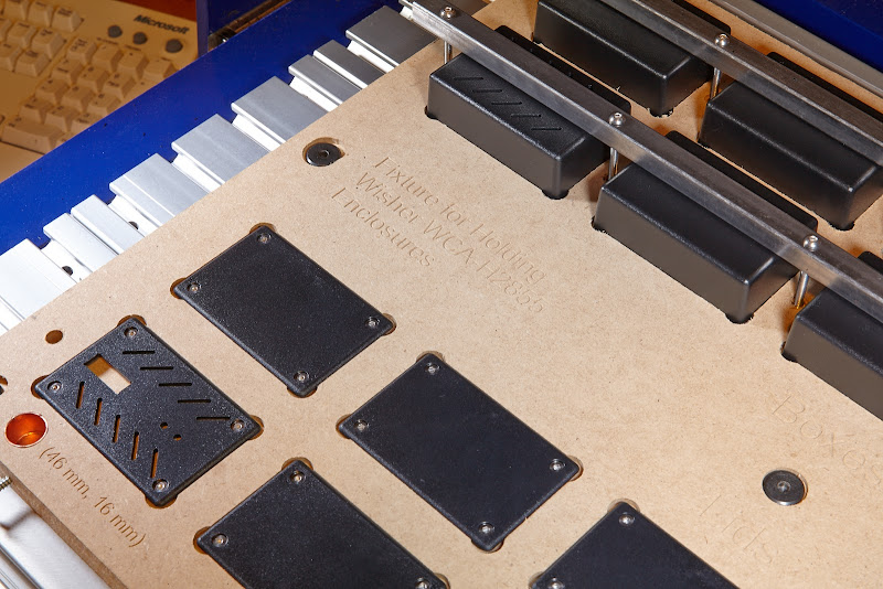
And here you go (too bad about the two misshapen countersink holes along the left side; my initial clamping—before I had all the holes drilled for the final clamping bolts—didn't hold!; other than that, no significant mistakes).
In case it's not obvious, the lower ten pockets hold the lids, and the upper ten pockets hold the lower part of the boxes. Since the lids have screw holes, they'll just screw (machine screws) into the threaded inserts in the fixture. The boxes have no holes, so they'll be held down from the top with some steel square tubing screwed (machine screws again) to the threaded inserts in-between and on the ends of each of the two rows. The threaded inserts should allow numerous fastening/removal cycles, unlike wood screws.
You'll also note the two copper-lined holes (they're actually 1/2" copper pipe end caps). These are reference points; the ShopBot can find the center of a metal circle (put small rod in collet, maneuver over hole, lower rod into hole, and run the code that finds the center by watching an input that completes a electric circuit between the rod and the metal part). Same principle that's used for setting the Z zero using a conductive plate on top of the Z reference point. Cool stuff. Anyway, those two reference points will allow me to remove this fixture from the table and then put it back later and get everything re-squared and zeroed based on those reference points.

(large version)

(large version)

(large version)

(large version)
I'm happy with this; it's my first CNC routing project ever after having the ShopBot for a little more than a week.
Enclosures: Because of the difficulty in producing acceptable (to me, at least) quality enclosures with professional-grade cooling slots and openings for the monitor and status LEDs and the connector, I decided to go crazy and get set up to produce these myself in quantity. I'm just about done with a fixture to hold the lids and boxes so they can be cut 10 at a time. I'll show photos of this fixture later tonight (I think I'm that close to done). Once the fixture is done, I'll be able to grind out the enclosures very quickly.
In case it's not obvious, the lower ten pockets hold the lids, and the upper ten pockets hold the lower part of the boxes. Since the lids have screw holes, they'll just screw (machine screws) into the threaded inserts in the fixture. The boxes have no holes, so they'll be held down from the top with some steel square tubing screwed (machine screws again) to the threaded inserts in-between and on the ends of each of the two rows. The threaded inserts should allow numerous fastening/removal cycles, unlike wood screws.
You'll also note the two copper-lined holes (they're actually 1/2" copper pipe end caps). These are reference points; the ShopBot can find the center of a metal circle (put small rod in collet, maneuver over hole, lower rod into hole, and run the code that finds the center by watching an input that completes a electric circuit between the rod and the metal part). Same principle that's used for setting the Z zero using a conductive plate on top of the Z reference point. Cool stuff. Anyway, those two reference points will allow me to remove this fixture from the table and then put it back later and get everything re-squared and zeroed based on those reference points.
(large version)
(large version)
(large version)
(large version)
I'm happy with this; it's my first CNC routing project ever after having the ShopBot for a little more than a week.
01-22-2013, 06:31 PM
#108
Nordschleife Master
Very cool. 
A small CNC/printing setup is on my current list of wants (there are a couple of open source designs for dual purpose 3d printing/CNC machines. I need to clear a heap of projects before I'll let myself go down that rabbit hole tho'
A small CNC/printing setup is on my current list of wants (there are a couple of open source designs for dual purpose 3d printing/CNC machines. I need to clear a heap of projects before I'll let myself go down that rabbit hole tho'
02-01-2013, 06:30 PM
#109
Track Day
Try this one: http://jenniskens.livedsl.nl/Technic...0to%20LEDs.pdf
02-03-2013, 03:47 AM
#110
Addict
Rennlist Member
Rennlist Member
Thread Starter
A little status update... I'll spread it across a few posts.
First, I made one final design change to the enclosures. I changed my mind about where I was going to apply labels, so I decided to make the cooling slots more symmetrical.
Using the ShopBot to make the enclosures was the most fun I've had in a long time. Had to make a video of just one lid being made. I did this one with the protective skirts and enclosure removed from the spindle; consequently, I couldn't use the dust extractor (but without the vacuum running, it's nice and quiet!). But at least you can see what's going on.
(I recommend clicking the YouTube button to watch this on YouTube and then select the HD version where you can actually see the details.)
That resulted in this (and you'll notice the lower left enclosure box/bottom is completed at this point, too):
(large version)
Here's the fixture loaded with ten enclosures (ten lids and ten boxes), ready to go:

(large version)
About 15 minutes later, the boxes are done:

(large version)
and about another 15 minutes after that, the lids are done:

(large version)

(large version)
Here's a single enclosure box/bottom being done:
And a clip from a batch of them being done:
They wind up looking like this when removed from the work-holding fixture:

(large version)
First, I made one final design change to the enclosures. I changed my mind about where I was going to apply labels, so I decided to make the cooling slots more symmetrical.
Using the ShopBot to make the enclosures was the most fun I've had in a long time. Had to make a video of just one lid being made. I did this one with the protective skirts and enclosure removed from the spindle; consequently, I couldn't use the dust extractor (but without the vacuum running, it's nice and quiet!). But at least you can see what's going on.
(I recommend clicking the YouTube button to watch this on YouTube and then select the HD version where you can actually see the details.)
That resulted in this (and you'll notice the lower left enclosure box/bottom is completed at this point, too):
(large version)
Here's the fixture loaded with ten enclosures (ten lids and ten boxes), ready to go:
(large version)
About 15 minutes later, the boxes are done:
(large version)
and about another 15 minutes after that, the lids are done:
(large version)
(large version)
Here's a single enclosure box/bottom being done:
And a clip from a batch of them being done:
They wind up looking like this when removed from the work-holding fixture:
(large version)
Last edited by Ed Scherer; 02-03-2013 at 03:16 PM. Reason: Add more videos; CNC stuff is fun to watch!
02-03-2013, 03:59 AM
#112
Addict
Rennlist Member
Rennlist Member
Thread Starter
Next, I'll show off the final rev 1A PCBs. They look very similar to the one I showed back in post #72, but they're actually a slightly newer revision that addresses some minor solderability issues I experienced with that earlier revision. They also have the proper silkscreen on the bottom side of the PCB.
These are ready to go. No known problems.

(large version)

(large version)

(large version)
If you haven't seen lead-free solder before, these probably look like cold solder joints. They're not, though. (That's not to say that I couldn't do better.)

(large version)

(large version)
These are ready to go. No known problems.
(large version)
(large version)
(large version)
If you haven't seen lead-free solder before, these probably look like cold solder joints. They're not, though. (That's not to say that I couldn't do better.
)(large version)
(large version)
02-03-2013, 04:09 AM
#114
Addict
Rennlist Member
Rennlist Member
Thread Starter
It's a pleasure.
Finally... serial number 1 is done, and I'm tooled up to produce a few this week. I think I can get a few done Sunday (today, but it kind of still feels like Saturday).
Unit serial number 1, about to be buttoned up:

(large version)
Cooling slots (top vs. bottom) line up nicely (but due to perspective distortion, it isn't captured perfectly in this photo):

(large version)
As you can see, I didn't skimp on the labeling, either.

(large version)

(large version)
Within a day or two, I'll decide on how to proceed with reestablishing contact with those of you who have expressed interest in these, finalize initial price, etc.
Oh... and in case you're wondering, I get to keep AILD-1 serial number 1. Along with a few prototypes. This one will go into my car within the next few days.
And that's it for tonight.
Finally... serial number 1 is done, and I'm tooled up to produce a few this week. I think I can get a few done Sunday (today, but it kind of still feels like Saturday
).Unit serial number 1, about to be buttoned up:
(large version)
Cooling slots (top vs. bottom) line up nicely (but due to perspective distortion, it isn't captured perfectly in this photo):
(large version)
As you can see, I didn't skimp on the labeling, either.
(large version)
(large version)
Within a day or two, I'll decide on how to proceed with reestablishing contact with those of you who have expressed interest in these, finalize initial price, etc.
Oh... and in case you're wondering, I get to keep AILD-1 serial number 1. Along with a few prototypes. This one will go into my car within the next few days.
And that's it for tonight.
Last edited by Ed Scherer; 02-03-2013 at 08:04 PM.
02-03-2013, 04:33 AM
#116
Rennlist Member
Ed: once again thanks for sharing your progress and congratulations on the final product! Your attention to details has driven this to true professional heights, very impressive.
That ShopBot looks like a lot of fun to work with, great tool.
That ShopBot looks like a lot of fun to work with, great tool.
02-03-2013, 05:32 PM
#119
Electron Wrangler
Lifetime Rennlist
Member
Lifetime Rennlist
Member
Wow - Ed love your mini CNC set-up - cool!
Ed follow-up question for you... how easy would it be to adapt your design to switch/dim the interior lights (Assuming they were all converted to LED...). I had made a purely linear (60W) fade up /fade out dimmer years ago - not currently in the car but did work...
Basically it followed the interior light relay with a fade up (quick) and fade out (slow) both rates were adjustable. Given the duty cycle of the fading period vs. the on or off time - it actually doesn't consume much power overall - so thermals are probably even less challenging (for LED's).
Seems it wouldn't be so different from this design except for the fader front end stuff
Anyway for the dash lights - I don't need one now - so I'll let the first batch go to those who need it now - But I will take one later when that demand is satisfied...
Alan
02-03-2013, 06:02 PM
#120
Addict
Rennlist Member
Rennlist Member
Thread Starter
Ed follow-up question for you... how easy would it be to adapt your design to switch/dim the interior lights (Assuming they were all converted to LED...). I had made a purely linear (60W) fade up /fade out dimmer years ago - not currently in the car but did work...
Basically it followed the interior light relay with a fade up (quick) and fade out (slow) both rates were adjustable. Given the duty cycle of the fading period vs. the on or off time - it actually doesn't consume much power overall - so thermals are probably even less challenging (for LED's).
Seems it wouldn't be so different from this design except for the fader front end stuff
There's also the "being thorough" part: considering things like robustness (surviving reversed power, shorted output, voltage spikes, and temperature extremes; being appropriately configurable; using existing controls (sometimes creatively); etc.). For an interior light dimmer/fader, some of those things might apply, some might not.
As to the interior light dimmer/fader... I haven't really looked into it. If it were to be a drop-in replacement for an existing relay, I guess the first thing I'd investigate is whether or not supply voltage would be present at all times when it's needed (particularly if you want fade-out). If it's not, then you'd need some on-board energy storage (big *** capacitor?) or perhaps just take the easy way out and have a terminal for a jumper wire to a constant power source.
Next time around, I'll probably go surface mount rather than through hole components. I elected to go with THT and avoided SMT this time (rationale: wanted to make it possible for others including those with aging eyes to easily assemble these with just simple tools) for this project, but if minimal space is a strict requirement (as it would be for a relay-size device), SMT would likely be a necessity.