

PWM dimmer for instrument backlighting after upgrading to LEDs
 08-14-2011, 06:28 PM
#16
Addict
Rennlist Member
Rennlist Member
Thread Starter
Shoot me a PM with some contact info, and we will figure something out. I can certianly get you cheaper boards than Express PCB. Is that what you did the layout in? If so, send me your schematic, and I and I will capture it for you in Eagle or DesignSpark so you can get a non proprietary Gerber to shop around with.
Yeah, I was using ExpressPCB because the price was right for my initial playing around.
 If I get more serious about this stuff, I'll get Eagle; I was looking at it (my nephew recommended it to me, too) but didn't want to mess with it until I got more serious about this stuff.
Until I get a BTS730 to play with, I won't know whether or not it's going to be as easy to use as it appears to be.
Thanks for the offer to Eagle-ize this; if things get to the point where a particular PCB is the right way to go, I might take you up on that.
If the infineon based circuit is tested and works, then that is a good option. However, if you have issues getting it to work, I would say we can get a stripped down version of the arduino to work. After you have the code, we can just burn it on new chips. Mot of the extras arent necessary... no USB/Serial bridge, status LEDS.... they can all be eliminated.
I've got a Nano powered up on my desk right now, but haven't really started to play with it.
Question: The LM2940 datasheet says: "Designed also for vehicular applications, the LM2940/LM2940C and all regulated circuitry are protected from reverse battery installations or 2-battery jumps. During line transients, such as load dump when the input voltage can momentarily exceed the specified maximum operating voltage, the regulator will automatically shut down to protect both the internal circuits and the load. The LM2940/LM2940C cannot be harmed by temporary mirror-image insertion. Familiar regulator features such as short circuit and thermal overload protection are also provided." So... do you really need that extra protection diode? If so, would a 1N4001 suffice or something more exotic?
Question: I've never researched the automotive power environment at all. Are the transients really that bad? Can you, for example, run typical single supply linear devices (like the INA122 I was prototyping with, specs say 2.2 to 36 V) directly off the car's 12 V, or do you need a voltage regulator (LM2940T-12
) for that, too? Also, I'm guessing that you don't need to worry about regulating the power you feed to power driver devices like MOSFETs, etc. Is that correct?If I get some time within the next few days (maybe even tonight), I'll see if I can whip up an Arduino Nano + MOSFET driver based PWM dimmer circuit on a Proto-Board. I guess that would be pretty darn small and could probably be assembled on a perfboard with no custom PCB required. I've got everything I need to do it, so I might as well give it a try.
For now, I need to go out and mow the lawn and do some other much less interesting tasks.
Last edited by Ed Scherer; 08-14-2011 at 06:48 PM.
 08-14-2011, 06:57 PM
#17
Rennlist Member
Diodes are cheap, so I just go ahead and use them. Plus they will add another voltage drop before the regulator so the thermal load will go down on the reg. As far as overall regulation goes, some devices aernt that sensitive, and you dont need to provide regulated "system" voltage. If you are concerned though, you can always use a zener or TVS to clamp down over a threshold voltage. This is good practice for expensive chips, but Infineon has a good history of including some of these features on the die. However, a cheap external and replaceable component can be good protection.
Thanks
Hans
Thanks
Hans
 08-14-2011, 07:20 PM
#18
Drifting

I guess I wasn't clear. Sorry.
What was proposed, was using one of the compact Arduino compatible development boards, which is an 'off-the-shelf' circuit board, thus eliminating the need to do any prototyping or PCB layout.
The BlinkM MaxM board already has the automotive suitable power supply built-in, so I thought that was a better solution. I don't know about the Uno or Pro Arduino boards, but there may be a add-on 5V power supply that's available for automotive use.
Thanks to the Arduino open source support team, these boards are extremely easy to program. The digital (microprocessor) solution provides a way to emulate analog hardware in software. For your PWM/dimmer application, coding in the C programming language would be very simple for a software guy like you.
So with the Ardino compatible BlinkM MaxM, you wouldn't need to do any breadboarding, PCB layout, or prototyping. It would be just a matter of programming it, make the necessary wiring adapters, and install it in a suitable 'black box' to be mounted under the car's dash. Even if you wanted to duplicate of-the-shelf digital solution on several cars, the cost would still be very low.
How you approach it is up to you. But it sounds like Hans is offering you some great support, so that should make your PCB fab work much easier.
08-14-2011, 07:54 PM
#19
Addict
Rennlist Member
Rennlist Member
Thread Starter
Thanks for that, Barry. Very clear and it makes sense. Bold stuff really jumps out. I read those parts twice.
Damn... somehow, I didn't dig into what you mentioned (the BlinkM MaxM) deep enough when you first posted that. I just looked again (especially at the datasheet), and you're right: it looks pretty darn promising. Somehow, I missed (the first time) that it'll drive 3 A. I'm not sure about the analog input capabilities yet (quick skim didn't convince me that it was ready for a very small input signal like you can get with some of the other Arduino boards that provide AREF), but I'll look into it more later.
Thanks again, Barry! I'm glad you posted again so I wouldn't miss this. The BlinkM MaxM is definitely worth following up on. I apologize for not being more thorough before. Too much stuff, too little time!
08-14-2011, 09:42 PM
#20
Drifting
It'll drive high current anode arrays. But for your 'high side' dimmer, you'll need it to drive your cathode arrays. You would need to substitute another power MOSFET driver IC on the channel you decide to use, similar to what's shown in the above schematics by G Forrest Cook. The BlinkM MaxM datasheet provides a complete schematic of board components.
08-17-2011, 09:58 PM
#21
Addict
Rennlist Member
Rennlist Member
Thread Starter
FWIW, I've got a nice, compact workable dimmer module up and running based on the Arduino Nano (because that's one of the first devices I got). At the moment, the whole circuit is the Nano plus four resistors, a general purpose NPN transistor and a P channel MOSFET.
The good:
The bad (as it stands now):
Miscellaneous notable things:
Next up: messing with the Arduino Pro Mini (a little cheaper and more appropriate for this project) and the BlinkM stuff. That stuff is on the way, but isn't in my hands yet. Oh... and (if I elect to pursue it further), messing with the Infineon BTS730 (still on back-order).
BTW, guys, you've got me hooked on microcontrollers now.
The good:
- Very compact. The Nano is very nice and small, and pretty much has all the goodies I needed (and I've been using the on-board LED as a status/heartbeat indicator that helped me tune a few things).
- A programmable device does have its advantages. I've been able to do a few things�like programming in some hysteresis to avoid some oscillations I noted on the first attempt�that wouldn't have been easy otherwise.
The bad (as it stands now):
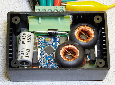
- The circuit is spewing some mighty nasty RFI. No big surprise there, as the MOSFET is rapidly switching a non-trivial amount of current. I'm aware of techniques to mitigate this (chokes on supply and various filters on output; e.g.: the inductor in the output stage of the "G Forrest Cook" schematics that Borland showed in post #2 in this thread; e.g.: the toroidal inductor you can see right before the output terminal of the PWM dimmer I showed in post #3), but I haven't had time to address this yet.
- Still a few more "add on" components than I'd like, but at least they're all discrete components that are perfboard-able.
Miscellaneous notable things:
- A nice side effect of the design is that if you disconnect the rheostat, the dimmer output is full bright.
- Did you know that perceived LED brightness and the necessary PWM duty cycle are related nonlinearly? I'm using a look-up table (based on some CIE lightness formulas) to address this.
Next up: messing with the Arduino Pro Mini (a little cheaper and more appropriate for this project) and the BlinkM stuff. That stuff is on the way, but isn't in my hands yet. Oh... and (if I elect to pursue it further), messing with the Infineon BTS730 (still on back-order).
BTW, guys, you've got me hooked on microcontrollers now.
Last edited by Ed Scherer; 08-17-2011 at 10:45 PM.
08-17-2011, 11:12 PM
#22
Rennlist Member
Ed,
Glad to hear its working out. I figured that would be faster and cheaper than trying to modify an off-the-shelf dimmer module.
One other function you could program into the arduino for potential customers would be digital dash correction for 89+ sharktuned cars. It would be a relatively easy task, just scaling the injector pulse by a correction factor to trick the dash into seeing the fuel in terms of the stock injector size.
I was thinking about including it in one of my projects, but I ended up needing the pins and resources. With just a simple PWM dimmer, the 328 has plenty of overhead for dash correction.
Just food for thought.
Thanks
Hans

 475hp/460lb.ft
08-17-2011, 11:31 PM
475hp/460lb.ft
08-17-2011, 11:31 PM
#24
Three Wheelin'
My eyes hurt.
I'm trying to understand what you're saying (NOT!) and at the end of the day I hope you guys figure out what will work best. You are ALL to be congratulated, and more important (in my world) RESPECTED for what you are doing for the benefit of this (relatively) small group of 928 enthusiasts. When you have it all figured out, tell us what it's gonna do (or not) and let it be done. You can't please everyone and you can't solve ALL the problems so lets just make it as good as we can and move on to the next issue.
Hans, I'm waiting for the "simple" solution to the HVAC. Please get it done. I may upgrade to the next level but I need a benchmark. The window/sunroof thing is cool. The speaker thing is cool. BUT, before we move to dimmers, lets get the HVAC thing done! I Love ya man, because what you are doing, I never could do, but damn..........I suffer from ADD, and you are creeping me out! (Meaning that in only the kindest way)
08-17-2011, 11:49 PM
#25
Rennlist Member
Paul,
This is Ed's project. Just trying to "help" give him some ideas and support.
I am perfectly content with quantity of projects I have on my plate... this one is all Ed.
Thanks,
Hans
This is Ed's project. Just trying to "help" give him some ideas and support.
I am perfectly content with quantity of projects I have on my plate... this one is all Ed.
Thanks,
Hans
08-18-2011, 01:17 AM
#26
Drifting
While your at it, can you add 'Voice Control' to that?
The article associated with those G Forrest Cook circuit diagrams, discusses the chokes (5 turn, 1/4" dia) and states that they can be wound on ferrite beads or wrapped on 10 ohm 1/4 watt resistor.
http://solorb.com/elect/pwm/pwm2/
I'm guessing that Cook used a air core, so you might want to use a online calculator the determine the inductance in uH...
http://www.daycounter.com/Calculator...lculator.phtml
I wonder if 'perceved brightness' is also non-linear with dark adapted or night vision?
Last edited by borland; 08-18-2011 at 02:03 AM.
09-07-2011, 08:22 PM
#27
Addict
Rennlist Member
Rennlist Member
Thread Starter
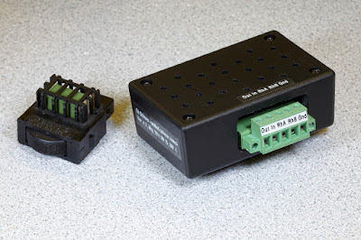
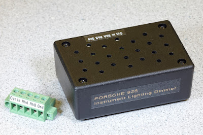
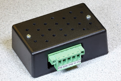
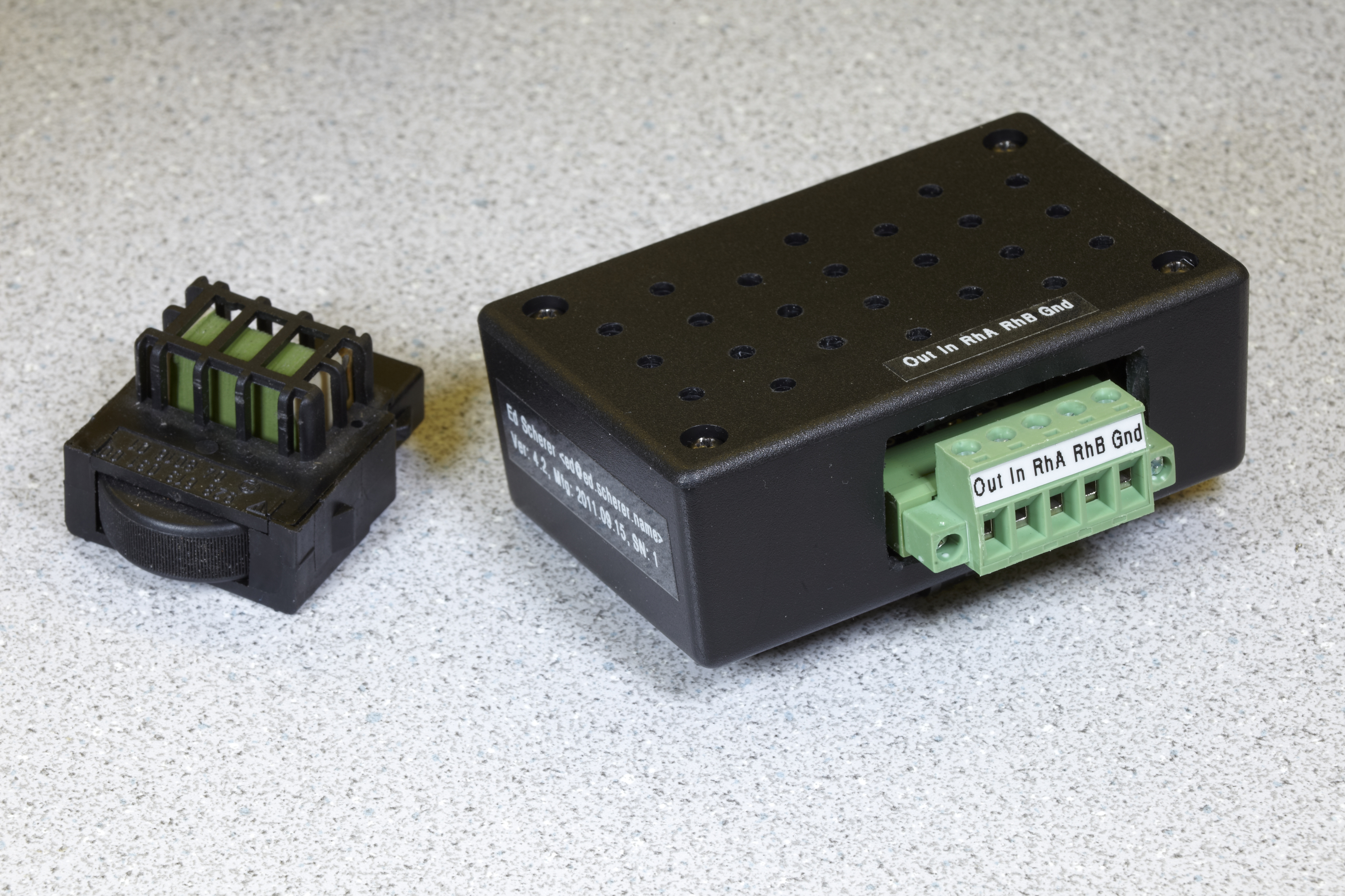
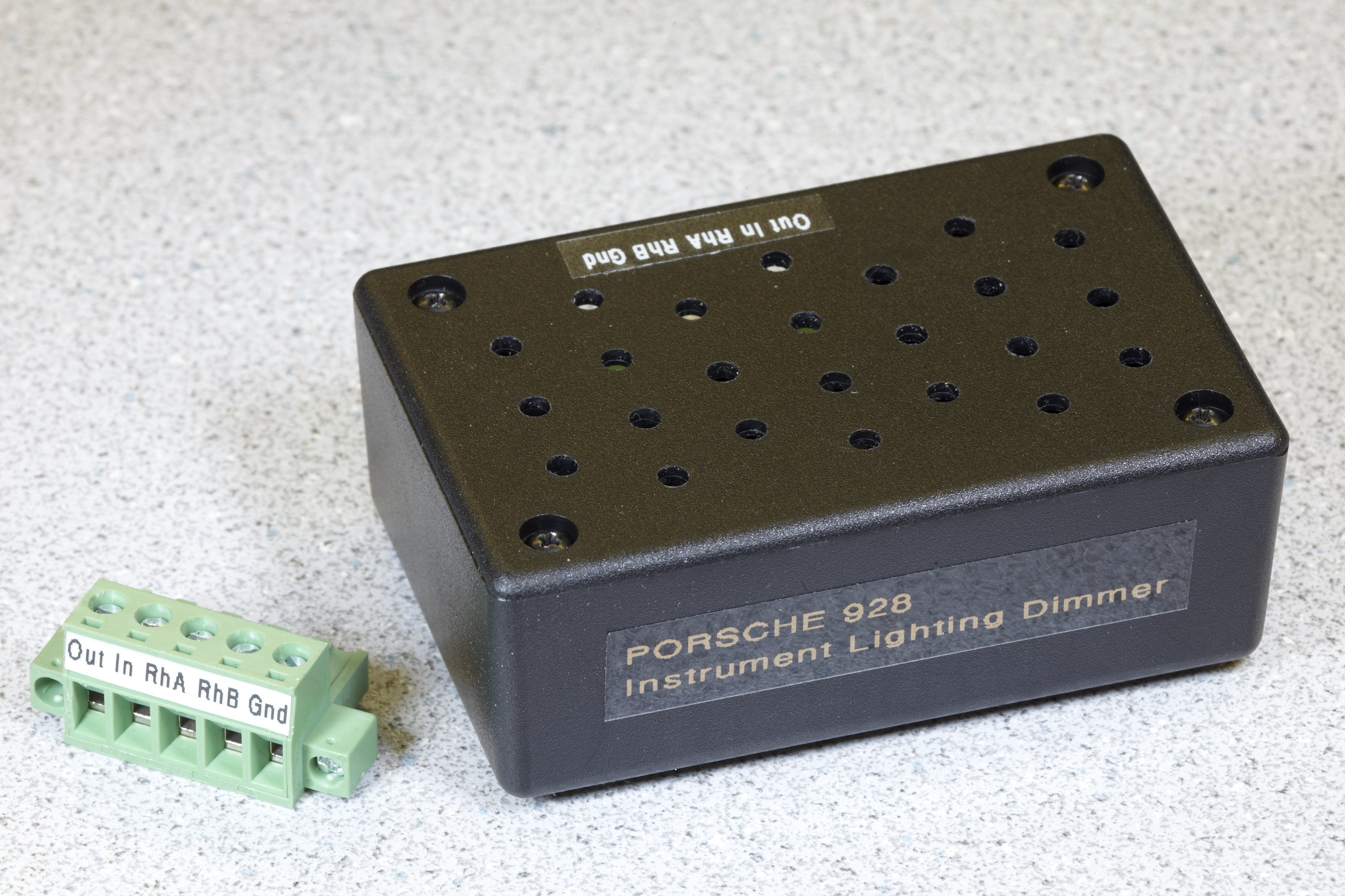
I got a usable, fairly well packaged dimmer module up and running yesterday (i.e., it's off the breadboard and into a 3.125" � 2" � 1.25" ABS box). Good enough for my car, anyway. All parts soldered into a pad-per-hole perfboard (man, I hate those things). Arduino Pro Mini based. I think I got the RFI problems licked.
The microcontroller-based approach was indeed handy. That allowed me to do a couple of things that would have been relatively hard otherwise: doing a slow fade (as appropriate, based on the rheostat setting) when the dimmer is first engaged, and locking in the dimmer level with a little hysteresis when it notices that the rheostat isn't being adjusted significantly anymore. Very nice.
Once again, thank you guys for pointing me in the direction of microcontrollers. Damn nice little devices and incredibly easy to work with. Cheap, too!


Last edited by Ed Scherer; 02-28-2012 at 09:34 PM.
09-08-2011, 11:42 AM
#29
Addict
Rennlist Member
Rennlist Member
Thread Starter
Without some filtering, just outputting a square wave generates all sorts of nasty high frequency harmonics: RFI galore. It's pretty cool to watch the TTL-level PWM signal from the microcontroller output (or the MOSFET driver output, which pretty much has the same shape) on one scope channel and then on the other channel, observe the output after a little filtering to smooth out the PWM pulses. Makes a huge difference in RFI. Ditto on the power supply side; that large pulsed draw from the power MOSFET driver feeds all the way back through the +12 V supply if you don't have some kind of filtering.
I find it kind of interesting that there's not as much discussion of this topic (RFI from PWM circuits) as I'd expect in the hobbyist electronics community. There are probably all sorts of RFI-spewing circuits being developed across the world.
Last edited by Ed Scherer; 09-08-2011 at 11:59 AM.
10-06-2011, 10:30 PM
#30
Addict
Rennlist Member
Rennlist Member
Thread Starter
I've had this dimmer installed and in use for a couple of weeks or so now and it's working great. IMHO, it's a great thing to do if you've done the LED upgrades to one or more of your instruments (cluster, A/C control head, pod switches, etc.).
No detectable RFI at all on AM or FM radio channels, I'm happy to report.
I'm still thinking about making this available to others, so I've continued trying to improve (and where possible, simplify) the circuitry. I've already got a slightly improved version that only needs one of the relatively large toroidal inductors. If there's any interest, I'd consider turning this into either a build-it-yourself kit or a completely assembled, ready-to-install item. IMHO, it really needs a proper PC board for any additional units, as it just takes too damn long to build using other prototype-grade techniques.