
CE Panel Refurb Questions
 01-14-2011, 04:29 PM
#1
Pro
Thread Starter
Join Date: May 2008
Location: Charlotte, NC
Posts: 580
Likes: 0
Received 0 Likes
on
0 Posts
I started my CE panel refurb project today. I planned to pull panel and replace all fuses and relays with new (already purchased) and add Stabilant22 in the appropriate areas.
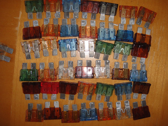
I pulled the panel earlier today and removed all the fuses/relays. I found that all but one of my fuses were fairly badly corroded. The one that wasn't was good 'ol fuse #25 which I replaced last year after I corrected a problem with the interior lights shorting out.
Fuses:
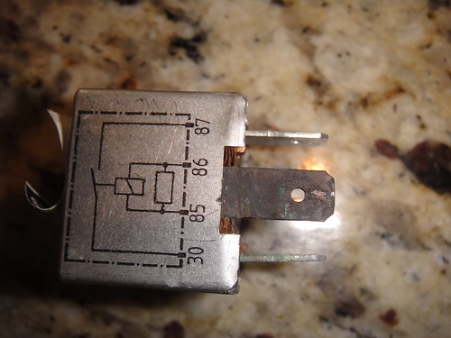
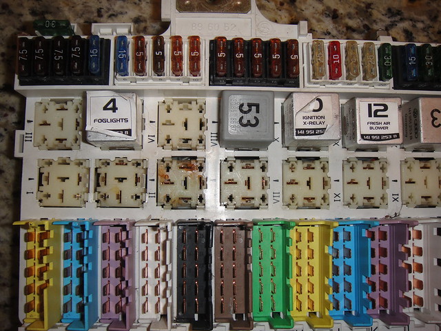
Most of the relays looked decent other than the ignition relay and the injector relay which had badly corroded spades (picture below is representative of both relays). Also, the panel had signs of arcing at the ignition relay (see second picture below).
I'm actually excited by these findings. My car has always started right up but I always thought it should fire up just a little sooner--wonder if the starter relay has something to do with that. I also have signs of hesitation that could be attributable to clogged injectors--my plugs always look whitish like I'm running lean. I've run a lot of Techron with no improvement. I wonder if the injector relay corrosion could be the source of that problem.
Ignition relay socket is diagonal (down and to right) of fog light relay.
My questions are these:
1) With all the fuses so badly corroded, should I be pulling out the connectors one by one from the back and trying to clean them--from previous posts this is generally not recommended. Alternatively I could get a custom thin electrical file made to clean female connectors but I worry that the fuses will no longer fit tightly if I go this route--some of them were already pretty easy to pull out, despite being caked with corrosion. Would another approach be to coat the new fuses with Stabilant22 and stick them back in without any cleaning?
2) Basically the same question goes for the relays. Should I be trying to clean the female receptors or simply replace the relays with new ones. I gathered from another post that Stabilant22 on relay connections is not recommended per the manufacturer (not to be used on switched connections).
Thanks for any suggestions.
Dan
I pulled the panel earlier today and removed all the fuses/relays. I found that all but one of my fuses were fairly badly corroded. The one that wasn't was good 'ol fuse #25 which I replaced last year after I corrected a problem with the interior lights shorting out.
Fuses:
Most of the relays looked decent other than the ignition relay and the injector relay which had badly corroded spades (picture below is representative of both relays). Also, the panel had signs of arcing at the ignition relay (see second picture below).
I'm actually excited by these findings. My car has always started right up but I always thought it should fire up just a little sooner--wonder if the starter relay has something to do with that. I also have signs of hesitation that could be attributable to clogged injectors--my plugs always look whitish like I'm running lean. I've run a lot of Techron with no improvement. I wonder if the injector relay corrosion could be the source of that problem.
Ignition relay socket is diagonal (down and to right) of fog light relay.
My questions are these:
1) With all the fuses so badly corroded, should I be pulling out the connectors one by one from the back and trying to clean them--from previous posts this is generally not recommended. Alternatively I could get a custom thin electrical file made to clean female connectors but I worry that the fuses will no longer fit tightly if I go this route--some of them were already pretty easy to pull out, despite being caked with corrosion. Would another approach be to coat the new fuses with Stabilant22 and stick them back in without any cleaning?
2) Basically the same question goes for the relays. Should I be trying to clean the female receptors or simply replace the relays with new ones. I gathered from another post that Stabilant22 on relay connections is not recommended per the manufacturer (not to be used on switched connections).
Thanks for any suggestions.
Dan
 01-14-2011, 05:08 PM
#2
Rennlist Member
Greetings.
This is what you _really_ need to do at this point.
http://members.rennlist.com/sharkski...04-Bzzzzzt.htm

This is what you _really_ need to do at this point.
http://members.rennlist.com/sharkski...04-Bzzzzzt.htm
The following users liked this post:
Amk3rd (05-21-2022)
01-14-2011, 05:19 PM
#3
Rennlist Member
Rennlist Site Sponsor

The Stabilant recommendation is to not apply the product to moving connections - i.e., the contact points. Applying it to the relay contacts is correct and desirable.
Good (but expensive) product.
Good (but expensive) product.
01-14-2011, 05:30 PM
#4
Pro
Thread Starter
Join Date: May 2008
Location: Charlotte, NC
Posts: 580
Likes: 0
Received 0 Likes
on
0 Posts
Hey Speedtoys. Yeah, I used Sharkskin's site to get started but I've got the newer CE panel. I don't have the old bullet fuses. Also, my connectors along the bottom (not sure what they're called but the ones that are released by the red tab) all look clean. It's my fuses and relays that look crummy and in order to clean the female sides I would need to start pulling apart the grey spaghetti in the back (or use an electrical spade file of some sort from the front).
01-14-2011, 05:32 PM
#5
Pro
Thread Starter
Join Date: May 2008
Location: Charlotte, NC
Posts: 580
Likes: 0
Received 0 Likes
on
0 Posts
Hey Wally, so I'm a little confused. So it's OK to put Stabilant22 on the male prongs of my new relays before I install them in the board? I'm not sure where I would find moving parts to apply Stabiliant to even if I wanted to--like the inside of the relay itself?
Thanks, Dan.
Thanks, Dan.
01-14-2011, 06:55 PM
#6
Pro
Thread Starter
Join Date: May 2008
Location: Charlotte, NC
Posts: 580
Likes: 0
Received 0 Likes
on
0 Posts
Anyone think that the arcing and corrosion I see on the ignition and injector relays could be due to higher resistance in those circuits? I.E. the scorching on the relay's is a sign of a problem in the downstream circuit rather than in the relay itself?
I did replace all my plugs, wires/ distributor caps, coils, and coil ground cables and cleaned all my ground points in the last year so hopefully those problems would be solved by now anyway...
I did replace all my plugs, wires/ distributor caps, coils, and coil ground cables and cleaned all my ground points in the last year so hopefully those problems would be solved by now anyway...
01-14-2011, 07:06 PM
#7
Rennlist Member
Did you stick your hand underneath where the panel goes, beneath the underlayment to check for moisture?
My guess is the arcing was caused by corrosion. Corrosion by moisture, either from fan seal above the panel, past mouse nest in the plenum, or both.
I cut a metal type nail file which is thin, with a chisle to form a thin narrow searated tool for cleaning the female terminals, btw. Pain.
Your car should run better, certainly you are at least preempting some roadside downtime!
Trending Topics
01-14-2011, 09:19 PM
#8
Rennlist Member
Do what Landseer suggests. Do not attempt to pull the connectors out from the rear to clean them. I have done a couple of CE panels, and completely pulled apart a spare panel to recover usable spare bits and pieces. You will damage the panel if you attempt to undo the gray spaghetti in the back, and you may never get it all back together again, or get it properly wired correctly.
Sharkskin's write up is great , but as you posted above, it is based on the early panels. Much on the info is good, but the fuse cleaning procedure won't work for you.
Sharkskin's write up is great , but as you posted above, it is based on the early panels. Much on the info is good, but the fuse cleaning procedure won't work for you.
01-14-2011, 10:31 PM
#9
Pro
Thread Starter
Join Date: May 2008
Location: Charlotte, NC
Posts: 580
Likes: 0
Received 0 Likes
on
0 Posts
Hey Chris, I definitely had water leakage over the CE panel before. I think this issue has been resolved for the most part. I took apart my HVAC intake recently and cleaned it out entirely and the recirc vent was recently resealed. I'm still waiting for a really heavy rain to retest this issue. In the past my passenger side floor would get wet if there was a torrential rain that I was caught in (car is a daily driver).
You're nail file suggestion is a good one. The nail file I have is smooth at the tip and rough further in but I could cut off the tip. It's also just a bit wider than the fuse blades but I could probably find a dremel attachment that I could use to make it a bit thinner (keeping the grooves on one side for cleaning).
You're nail file suggestion is a good one. The nail file I have is smooth at the tip and rough further in but I could cut off the tip. It's also just a bit wider than the fuse blades but I could probably find a dremel attachment that I could use to make it a bit thinner (keeping the grooves on one side for cleaning).
01-14-2011, 10:34 PM
#10
Pro
Thread Starter
Join Date: May 2008
Location: Charlotte, NC
Posts: 580
Likes: 0
Received 0 Likes
on
0 Posts
Ed, it's quite tempting to try to pull out the grey wires one by one and get them clean--it's good to hear that it's been tried and generally does not go well. I'm starting to wonder why I pulled the CE panel in the first place. I guess I could've just pulled all the fuses and relays, cleaned them with a file in situ and then replaced with new fuses/relays painted with Stabilant22. I guess it will be a bit easier to file the female sides with the CE board on the table but I worry about what gremlins I may have created by bending/flexing all the wires to get the CE board out.
Last edited by Manfred; 01-14-2011 at 10:35 PM. Reason: typo
01-14-2011, 10:51 PM
#11
Rennlist Member
That's essentially what I used, but I used a points file(remember those?). Also I removed each female connector from each relay socket and fuse connector one at a time, cleaned them and gave them a squeeze so they would grip the male connector more tightly, and put them back.
The later panel fuse blocks are modular, you can take them out, take them apart, and tighten them up the same way -- but I recommend you do one block at a time. If you don't tighten them up they will be loose, they will heat up and corrode and that's just the good part at the beginning -- you can imagine the rest. You can mark the wires prior to disassembly with multi-colored mini zipties. If a block has 10 wires attached, and you only have white, red, green, blue and yellow zipties, then put one color ziptie on the two wires for one fuse, but make a mark on the upper(or lower) one with a sharpie. Once you have all the wires for one block marked, take a picture, then take it apart, clean, reassemble, and remove the zipties. Rinse and repeat. I'm pretty sure they come all thee way apart, meaning you can separate the contacts from the plastic and refurb the contacts.
TBH it's been a couple years since I looked at the backside of a later panel, so I don't remember exactly how the wires connect up. Now that I think of it I seem to recall there are one or two common bus connections for all 5 fuses then 5 fused connections on the other side. Anyway, take it slow and check your work, don't take too much apart at once and you'll be fine.
01-14-2011, 11:17 PM
#12
Pro
Thread Starter
Join Date: May 2008
Location: Charlotte, NC
Posts: 580
Likes: 0
Received 0 Likes
on
0 Posts
Thanks Dave. I looked at a couple points files online but none of them had specs as far as their thickness or width was concerned so I wasn't couldn't be sure they would work. Would your standard ignition point file work?
I just took a look at the fuse blocks. There are ten wires/block so if you go slow, it's doable. The only question I have is this:
The grey wires have female terminals. They connect to male terminals on the back side of the fuse blocks. On the front side of the fuse block, there are female terminals presented to the male spade fuses. So there is a separate metal connector in the fuse block that's male on the back and female on the front. The part I need to clean is the female connector on the front (a quick visual inspection of the grey wire female connector and male fuse block connector on the back seems to indicate no corrosion issues there). That said, I could pull off all the grey wires I want but I don't think that would afford me any greater access to the female connectors on the front. Has anyone taken apart the fuse blocks before? Can you get better access to the forward facing female connector by taking them apart or is going after them with a points file about the best you can do?
01-14-2011, 11:36 PM
#13
Rennlist Member
Rennlist Site Sponsor
Dan,
Yes use Stabilant on the connectors. Stabilant should not be used on moving contacts inside the relays.
I would not use a metal file on the connectors, but would make abrasive files using fine abrasive paper. The idea is to clean the connectors while removing the minimum amount of metal possible.
There is another chemical that will help - DeoxIT from Caig Labs. This is an excellent contact cleaner that might reduce or eliminate the need to mechanically clean the connectors.
The brown marks around the connectors are due to heating. When one of the connectors develops some resistance due to corrosion or looseness, the electrical flow thru the resistance creates heat in the connection. This causes corrosion, which increases the resistance, which increases the heat, which increases the corrosion, which...
This burning is due only to the resistance in the connector, not to any increased resistance downstream, or any increased current flow.
01-14-2011, 11:51 PM
#14
Rennlist Member
Dan, look it over carefully. It all comes apart, you just have to crack the code. 
Wally, the only thing that makes me nervous about that is it's not clear what the long-term effects are of having DeOxit wick up the wires -- though lots of people have done it and I haven't heard any disaster reports.
BTW the points file I have is very fine, and I only used a single swipe -- that was all that was needed.
01-15-2011, 01:49 AM
#15
Rennlist Member
If taking it apart from the rear is what he really wants to do, get a cheap donor board like I did (a used CE panel) and practice on that first. My .02.
PS - Dave - I never would have attempted many of he things I've done without the likes of you, Dwayne and others paving the way
