
HVAC COMPRESSOR RELAY REPAIR PROCEDURE w/PICS
 09-16-2011, 03:23 PM
#76
Three Wheelin'
I replaced my clear plastic pin with an SMD LED and then drilled a small hole through for the wires. Result is the fan **** lights up at night!
Kenny
Kenny
Good point.
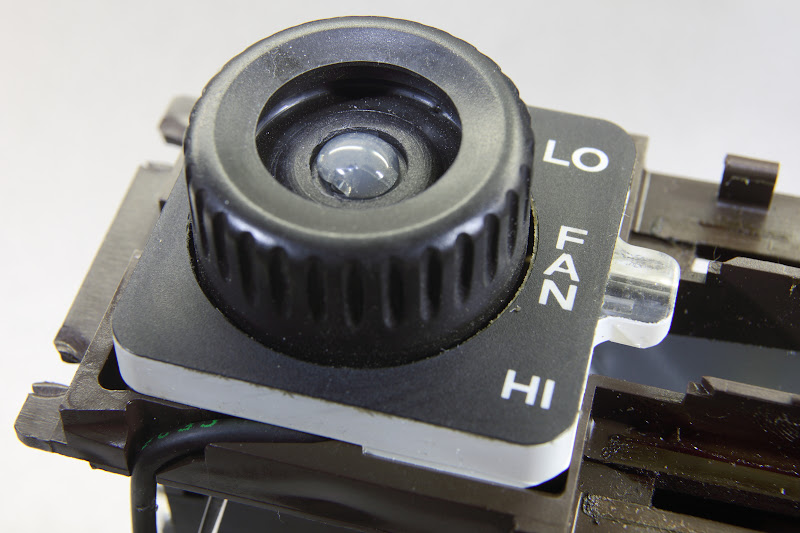
I believe the plastic pin you're talking about is the one inside the little part that extends past the main square part of #4; this extension houses #10.
If that's correct, and the plastic pin breaks, it seems like a potential repair would be to drill a hole through the extension piece on #4 where the plastic pin was and insert and glue in a stronger (than plastic) metal pin. Not remembering exactly what it looks like, though, I'm not 100% sure that's doable.
And you're right�you have to be really careful when reassembling these parts and make sure everything is meshing correctly rather than forcing the parts together.
BTW, you can see the clear plastic pin in this photo (look on the right of the #4 piece inside the clear plastic area). Click on the photo for a larger version.

 09-16-2011, 07:54 PM
#77
for measuring dc current up to 400 amps w/o going inline try ma-220 ex-tech instruments works great. NO affiliation. just like it and only cost what a good meter would cost,iirc about 120.00
What you just described makes good sense - for the AC circuit primarly - because that happens to be much more accessible for individual connections than most..
However it isn't what you actually said before..
You said..
Now its obvious what you actually meant by that - but the literal reading is quite different..
I point these things out because lots of folks know very little about electrical debug and are looking for good easy techniques - and its important not to set them off down the wrong path. Especially in a generic sense - current probing is hard to even do in most 928 circuits - e.g. multipole connectors and all...
And genericaly for debug it usually isn't actually needed and to me would always be a secondary technique.
I am not an armchair quarterback either - I do spend a lot of time helping people debug challenging things... often their measurement tools & techniques are not so good and it helps to keep it simple... You seem to have a good idea what you are doing - but its really isn't easy to implant that to others...
Alan
I try not to post things that are wrong - But I see no inaccuracies in what I said above...
09-16-2011, 10:40 PM
#78
Drifting
Alan,
Thank you for the write up. I will be doing this soon and post the results. I have a couple of more questions.
Where do i get the female pins that goes into the CE?
Would a 53 relay work?
Are the points marked on the back of the CE panel?
Thanks
Bilal
Thank you for the write up. I will be doing this soon and post the results. I have a couple of more questions.
Where do i get the female pins that goes into the CE?
Would a 53 relay work?
Are the points marked on the back of the CE panel?
Thanks
Bilal
09-17-2011, 01:48 PM
#79
"it seems like a potential repair would be to drill a hole through the extension piece on #4 where the plastic pin was and insert and glue in a stronger (than plastic) metal pin. Not remembering exactly what it looks like, though, I'm not 100% sure that's doable."
That's it! Rebuilt many (too many to remember) that way.
That's it! Rebuilt many (too many to remember) that way.
09-18-2011, 07:54 PM
#80
Drifting
Alan,
Thank you for the write up. I will be doing this soon and post the results. I have a couple of more questions.
Where do i get the female pins that goes into the CE?
Would a 53 relay work?
Are the points marked on the back of the CE panel?
Thanks
Bilal
Thank you for the write up. I will be doing this soon and post the results. I have a couple of more questions.
Where do i get the female pins that goes into the CE?
Would a 53 relay work?
Are the points marked on the back of the CE panel?
Thanks
Bilal
09-20-2011, 11:28 AM
#82
Electron Wrangler
Lifetime Rennlist
Member
Lifetime Rennlist
Member
'53 or generic Bosch style SPDT relays will both work. Genuine Bosch or Tyco.
Everything is marked on the front of the panel. send me a PM w/ email and I'll send you some more details on the relays. You can get the stock large relay terminals from Eagle Day or Vehicle Wiring Products (UK) - I got a lot from VWP(UK). I belive Roger (ROG100) also sells them individually. You can also use Ford standard terminals - though they are not such high quality.
There are some techniques that are usefiul to know for removing relay sockets & terminals.
Alan
 02-02-2012, 08:50 PM
#84
Rennlist Member
Wrapped this up today with the $9 radio shack relay. Bought it at the mall! Nice to see that at least some radio shacks still are true to their origins.
Tips: Remember REMEMBER DO NOTDO NOT crank the heat all the way up on your soldering iron. My board now requires a couple extra jumper wires because I cooked the PCB contacts right off the @$%^@! board.
Solder wick or a real vacuum solder tool is your friend. After all the electrical work I do I'm amazed I didn't have one of these 10 years ago.
I'm going to add another tricky bit to my install with an extra switch to enable/disable the compressor, but use the stock signals and switching to kick on both fans for those sit-on-rt66-at-100F moments. Or anywhere else I want to flog the crap out of the car and don't car about having the AC load on.
02-03-2012, 05:02 PM
#87
"Wrapped this up today with the $9 radio shack relay."
Hopefully, you checked the clutch current, as the original relay was destroyed by excessive
compressor clutch current, i.e. Much more than the normal current of about 3 amps.
Hopefully, you checked the clutch current, as the original relay was destroyed by excessive
compressor clutch current, i.e. Much more than the normal current of about 3 amps.
02-03-2012, 05:56 PM
#88
Rennlist Member
In the past this car fragged two different compressors, that's what took out the relay. I'm 70% done with complete cleanining and flushing of the entire system.
05-27-2012, 01:16 PM
#89
Drifting
So, I started doing the AC compressor relay install in the CE panel. I did not get far. I cannot get the connectors at the bottom of the panel off. I was using Allen's write up of using the loops on either side of the connector, but they are so brittle that even with a little pressure they break right off.
So is it really worth going this route? Or just try and put something in the engine bay?
So is it really worth going this route? Or just try and put something in the engine bay?
07-20-2012, 03:00 AM
#90
Three Wheelin'
Join Date: Jun 2008
Location: Surprise, Arizona
Posts: 1,914
Likes: 0
Received 0 Likes
on
0 Posts
Hello everyone!
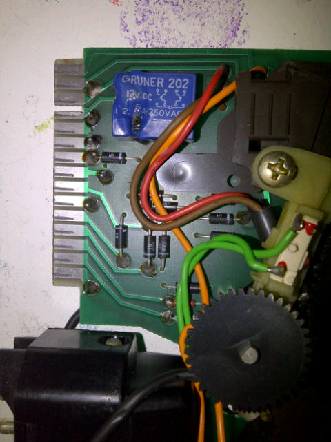
I have been putting off this job for some time, but the temps lately have spurred some motivation in me. While troubleshooting my non-op AC, I had the AC switch engaged and smoke started pouring out of the AC head unit. I was assuming I'd find a melted AC relay. I went down to Radio Shack and picked up the relay (Radio Shack part# 275-0218) for the job I have been putting off. I decided to pick up the socket (Radio Shack part# 275-0220) for the relay as I intend on making a fancy mount to allow replacement of the relay without head removal. I also picked up an in-line fuse for the internal relay and an in-line fuse for the freeze switch. When I got the head unit pulled, cleaned up, and dis-assembled, what I found is not what I was expecting. The relay does not look melted, but there are plenty of burnt areas on the board. (particularly the diode on pins 7 and 11 of the 15 pin connector) It's pretty obvious this is where the smoke was coming from. Also, there is the wire from the mode selector slider... It's pulled out of the crimp terminal on the opposite end and looks like it can possibly make contact with the surrounding solder points around the terminal. Does the damage in the photos look indicative of a relay failure? I'll check the freeze switch and low pressure switch, and also check the compressor clutch tomorrow, but for tonight I ask what everyone thinks...
This is on an '84...
Thanks in advance,
Mike
Last edited by 86'928S MeteorGrey; 07-20-2012 at 03:15 AM. Reason: added vehicle year