

Torque Tube, Torque Converter Bearing Replacement Procedure w/pics
 12-19-2010, 10:24 PM
#46
Three Wheelin'
Thread Starter
Join Date: Sep 2007
Location: Ridgecrest, California
Posts: 1,363
Likes: 0
Received 148 Likes
on
32 Posts
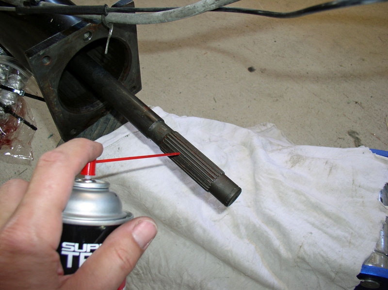
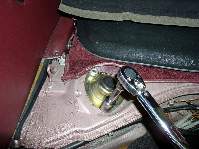
Before installing the bell housing and forward drive shaft clamp, clean the forward splines. I used brake cleaner and a wire brush to remove any grease, dirt and debris.
Position the bell housing over the drive shaft and align it to the TT using the locating pins on the bell housing. I found it helpful to temporarily insert two of the 17mm bolts that secure the bell housing to the TT to keep the bell housing in place for the next step.
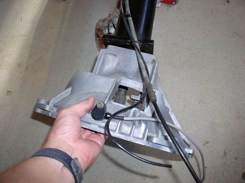
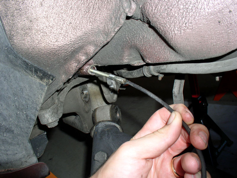
Next, secure the Bowden cable housing and vacuum line to the bell housing using the 5mm Allen Head bolt and clamp as shown in the picture below.
I installed Constantine�s Super Clamp as part of this job. At this point I slid the Super Clamp onto the drive shaft splines with the Allen Head bolts facing toward the rear of the car. No need to tighten the Allen Head bolts at this time.
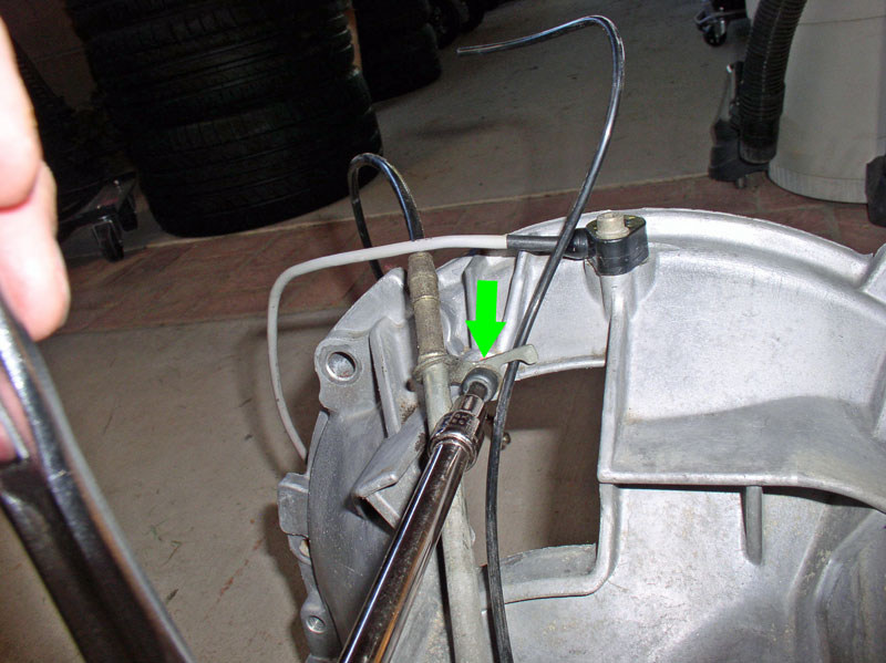
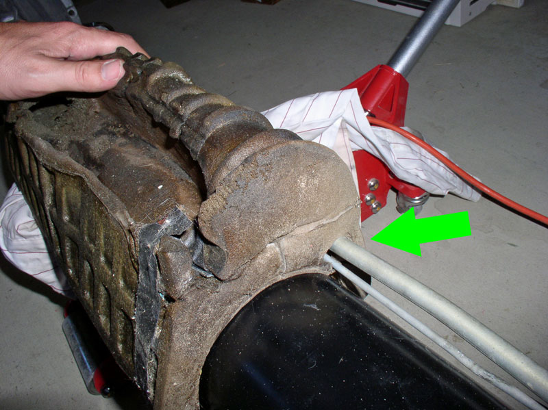
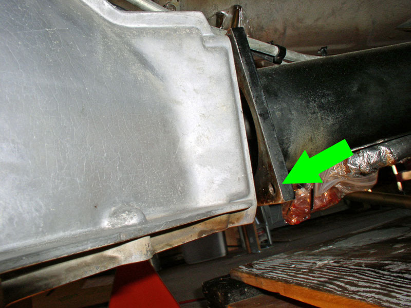
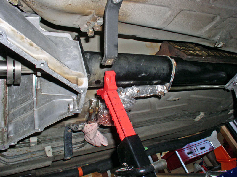
Lastly, I tightened all three of the band clamps to the TT since the lines are all secure at this point. I then installed the sound absorber on top of the TT between the marks I painted on the TT earlier when it was removed. Ensure the Bowden cable housing the vacuum line are inserted into their formed cutout in the sound absorber as indicated by the green arrow in the picture below. Originally, the sound absorber was held in place on the TT with a single strip of black tape at the rear of the sound absorber (see picture). You may want to install a new piece of tape (such as black electrical tape) to keep the sound absorber in place during the transmission/TT installation steps that will follow.
Position the bell housing over the drive shaft and align it to the TT using the locating pins on the bell housing. I found it helpful to temporarily insert two of the 17mm bolts that secure the bell housing to the TT to keep the bell housing in place for the next step.
Next, secure the Bowden cable housing and vacuum line to the bell housing using the 5mm Allen Head bolt and clamp as shown in the picture below.
I installed Constantine�s Super Clamp as part of this job. At this point I slid the Super Clamp onto the drive shaft splines with the Allen Head bolts facing toward the rear of the car. No need to tighten the Allen Head bolts at this time.
Lastly, I tightened all three of the band clamps to the TT since the lines are all secure at this point. I then installed the sound absorber on top of the TT between the marks I painted on the TT earlier when it was removed. Ensure the Bowden cable housing the vacuum line are inserted into their formed cutout in the sound absorber as indicated by the green arrow in the picture below. Originally, the sound absorber was held in place on the TT with a single strip of black tape at the rear of the sound absorber (see picture). You may want to install a new piece of tape (such as black electrical tape) to keep the sound absorber in place during the transmission/TT installation steps that will follow.
 12-19-2010, 10:49 PM
#47
Three Wheelin'
Thread Starter
Join Date: Sep 2007
Location: Ridgecrest, California
Posts: 1,363
Likes: 0
Received 148 Likes
on
32 Posts
CH14 INSTALLING TRANSMISSION AND TT
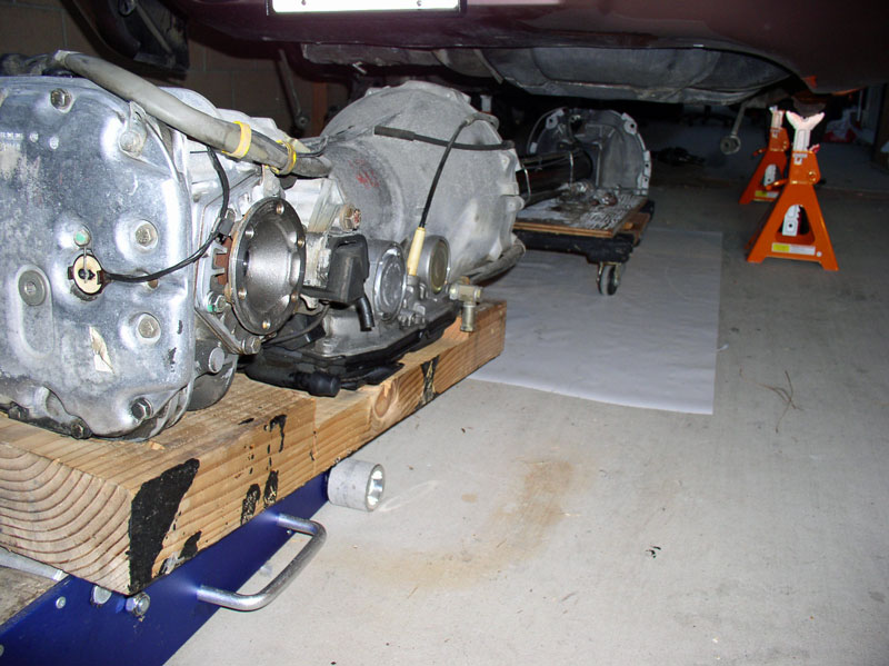
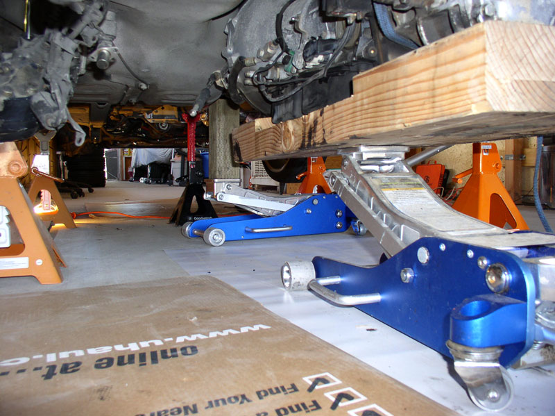
Before installing the transmission and TT, I gave the transmission a general cleaning with some citrus degreaser cleaner and a nylon brush � nothing too detailed, just clean most of the grease and dirt off. I supported the forward end of the TT on the furniture dolly and scrap plywood in the same manner as the removal. I maneuvered the transmission and forward end of the TT so that it was aligned with the centerline of the car with the forward end of the TT just under the rear license plate. I then pushed them forward into position under the car as pictured below. It was important to get the transmission aligned with the center line as it is very difficult to move the transmission left or right while it is resting on the floor jack (moving forward and backward work great!).
Once in position, use a 2nd floor jack to support the forward end of the TT as pictured below. Remove the furniture dolly.
I began raising the transmission and forward end of the TT using the floor jacks a couple of inches at a time. I took my time watching for possible snags and hang ups. As you raise the transmission, make sure it is positioned forward enough to clear the fuel tank heat shield as pictured below.
If you installed the temporary Bell Housing-to-TT bolts earlier to hold the Bell Housing in place, now�s the time to remove them again. This will allow the Bell Housing to move freely about while maneuvering it up and around the flywheel, the heat shields, and lining it up with the engine and TT � I found it makes the job MUCH easier.
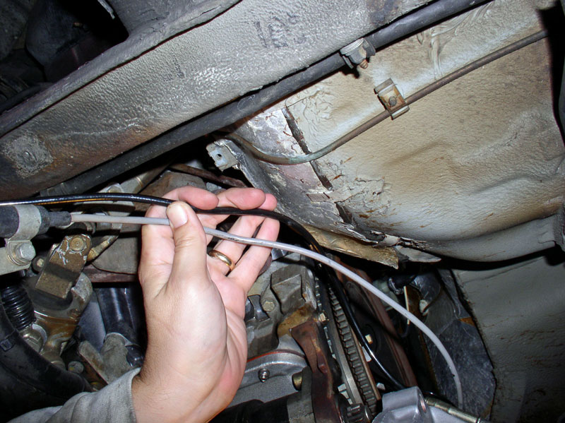
Before raising the forward end of the TT too high, locate and maneuver the Flywheel Position Sensor Cable (gray), the Bowden cable, and the vacuum line up into position between the rear of the engine and the firewall.
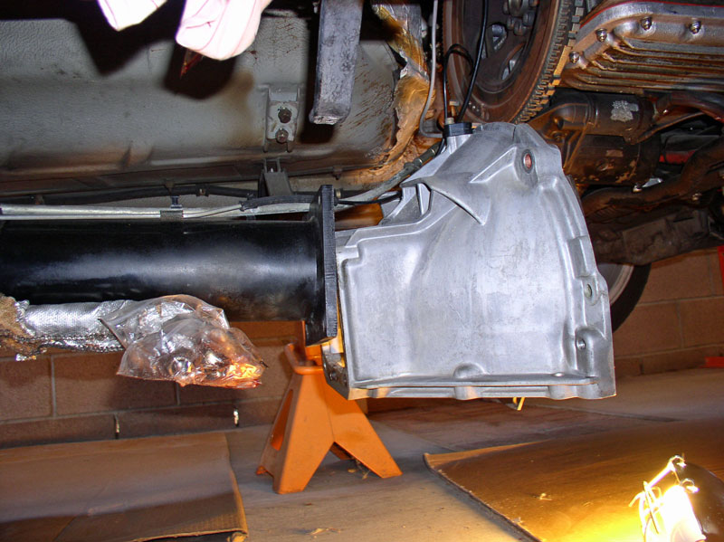
The forward end of the TT should look something like the picture below as you are ready to raise it into position.
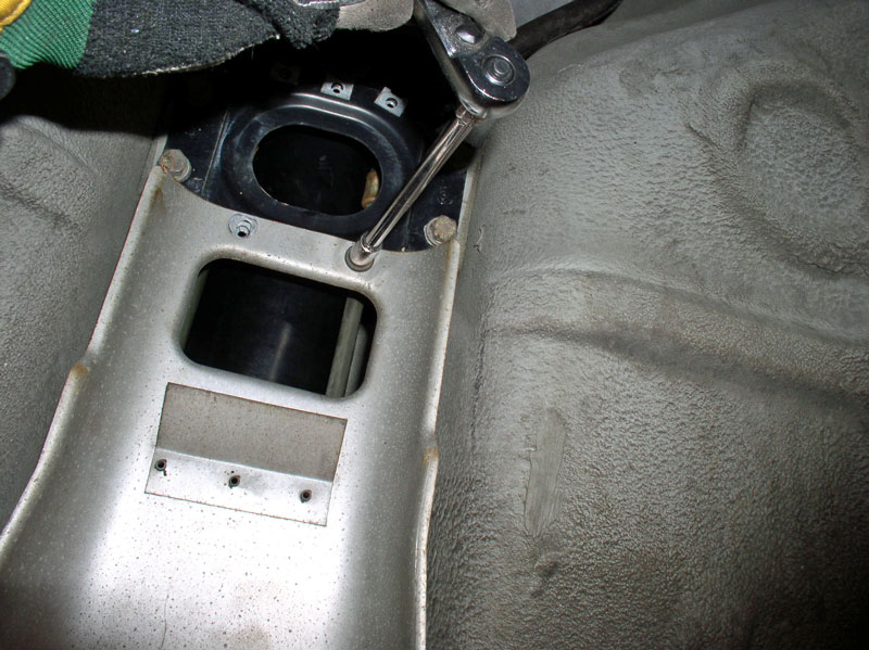
At the transmission, thread the transmission wiring harness leads through the access port in the spare tire compartment as shown below.
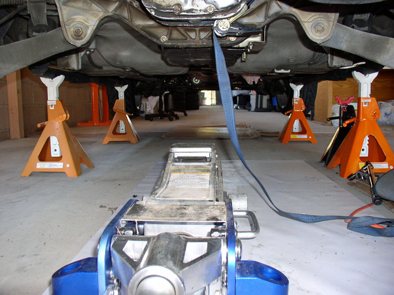
I raised the transmission and TT alternately a couple of inches at a time using the floor jacks. I also placed a jack stand at the forward end of the TT for additional safety. As you raise the assembly, continue checking for alignment and snags and make corrections as you go.
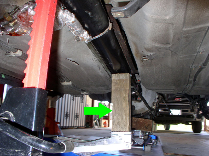
At some point, my floor jack was not tall enough to raise the TT. I placed a scrap piece of 4 X 4 on the floor jack pad and used it to gain the extra lift I needed. The jack stand at the forward end is always in place for additional safety.
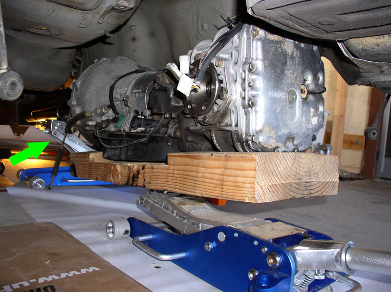
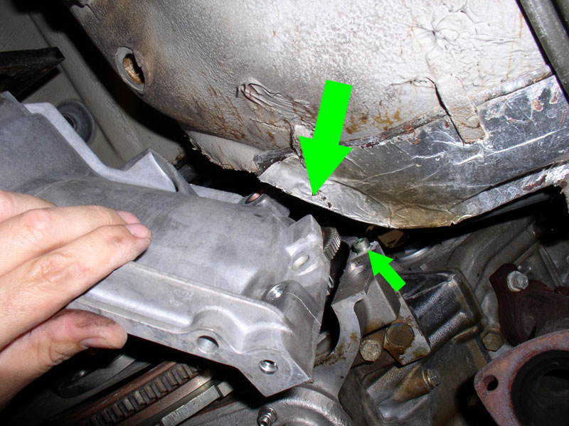
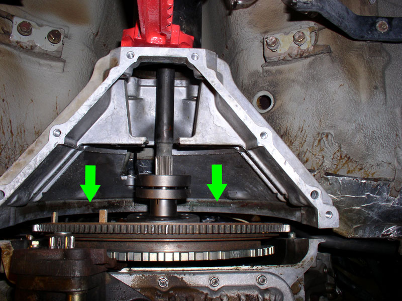
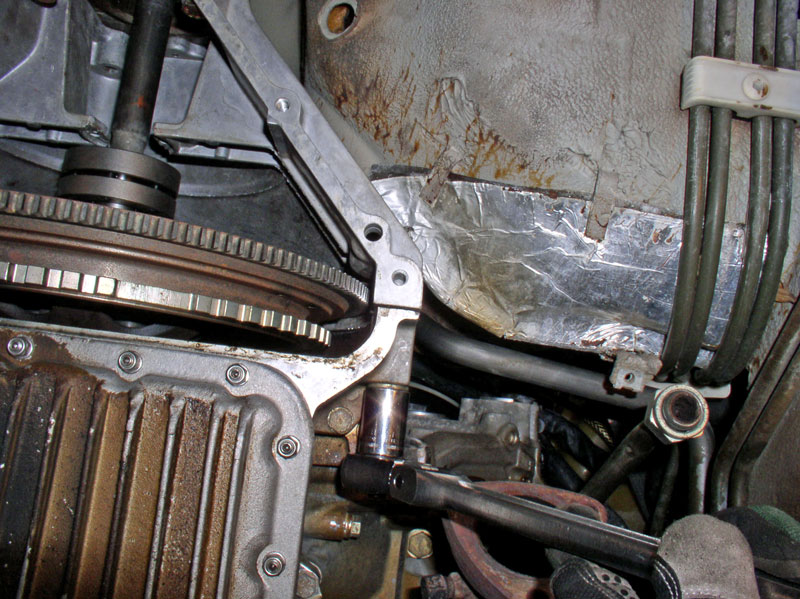
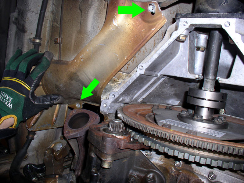
As you near the final height of the TT, you will need to begin maneuvering the bell housing around the firewall heat shielding on both sides. I found the notch in the Bell Housing casing pointed at by the large green arrow, to be the area that is a tight fit. It is quite possible to maneuver the Bell Housing into place without damaging the heat shielding if you take your time. You will also notice the locating pin on the engine block (indicated by the smaller green arrow) that will mate to the bell housing when it is in proper position. There is a locating pin on both sides of the engine block.
As you continue to raise and position the Bell Housing into position, remember to check the Bowden cable, flywheel position cable, and vacuum line to make sure they are not interfering with the installation. You should be able to grasp them from above to ensure they are not hung up.
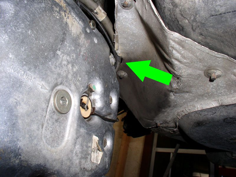
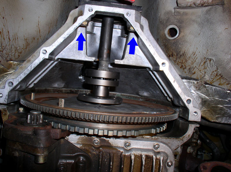
Once you clear the heat shielding, the next step is to maneuver the top of the Bell Housing (indicated by the green arrows) up and over the top of the flywheel
Adjust the height and/or forward position of the transmission and TT to provide maneuvering space, if needed.
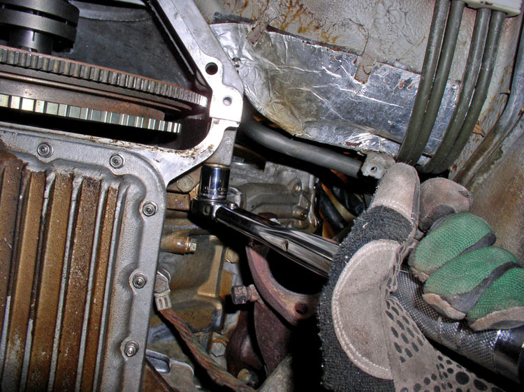
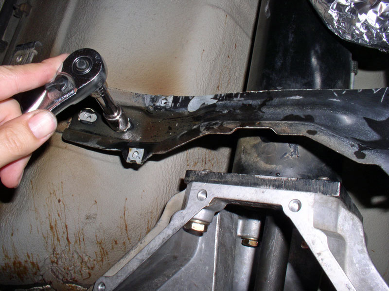
Once you have cleared the top of the flywheel, maneuver the Bell Housing to line it up with the TT locating pins and press the Bell Housing onto the locating pins. I installed the lower two 17mm bolts and snugged them down with the socket wrench to secure the Bell Housing to the TT.
Next, I pressed the Bell Housing over the locating pins on the engine block and installed the two 19mm bolts��
Continued....
Before installing the transmission and TT, I gave the transmission a general cleaning with some citrus degreaser cleaner and a nylon brush � nothing too detailed, just clean most of the grease and dirt off. I supported the forward end of the TT on the furniture dolly and scrap plywood in the same manner as the removal. I maneuvered the transmission and forward end of the TT so that it was aligned with the centerline of the car with the forward end of the TT just under the rear license plate. I then pushed them forward into position under the car as pictured below. It was important to get the transmission aligned with the center line as it is very difficult to move the transmission left or right while it is resting on the floor jack (moving forward and backward work great!).
Once in position, use a 2nd floor jack to support the forward end of the TT as pictured below. Remove the furniture dolly.
I began raising the transmission and forward end of the TT using the floor jacks a couple of inches at a time. I took my time watching for possible snags and hang ups. As you raise the transmission, make sure it is positioned forward enough to clear the fuel tank heat shield as pictured below.
If you installed the temporary Bell Housing-to-TT bolts earlier to hold the Bell Housing in place, now�s the time to remove them again. This will allow the Bell Housing to move freely about while maneuvering it up and around the flywheel, the heat shields, and lining it up with the engine and TT � I found it makes the job MUCH easier.
Before raising the forward end of the TT too high, locate and maneuver the Flywheel Position Sensor Cable (gray), the Bowden cable, and the vacuum line up into position between the rear of the engine and the firewall.
The forward end of the TT should look something like the picture below as you are ready to raise it into position.
At the transmission, thread the transmission wiring harness leads through the access port in the spare tire compartment as shown below.
I raised the transmission and TT alternately a couple of inches at a time using the floor jacks. I also placed a jack stand at the forward end of the TT for additional safety. As you raise the assembly, continue checking for alignment and snags and make corrections as you go.
At some point, my floor jack was not tall enough to raise the TT. I placed a scrap piece of 4 X 4 on the floor jack pad and used it to gain the extra lift I needed. The jack stand at the forward end is always in place for additional safety.
As you near the final height of the TT, you will need to begin maneuvering the bell housing around the firewall heat shielding on both sides. I found the notch in the Bell Housing casing pointed at by the large green arrow, to be the area that is a tight fit. It is quite possible to maneuver the Bell Housing into place without damaging the heat shielding if you take your time. You will also notice the locating pin on the engine block (indicated by the smaller green arrow) that will mate to the bell housing when it is in proper position. There is a locating pin on both sides of the engine block.
As you continue to raise and position the Bell Housing into position, remember to check the Bowden cable, flywheel position cable, and vacuum line to make sure they are not interfering with the installation. You should be able to grasp them from above to ensure they are not hung up.
Once you clear the heat shielding, the next step is to maneuver the top of the Bell Housing (indicated by the green arrows) up and over the top of the flywheel
Adjust the height and/or forward position of the transmission and TT to provide maneuvering space, if needed.
Once you have cleared the top of the flywheel, maneuver the Bell Housing to line it up with the TT locating pins and press the Bell Housing onto the locating pins. I installed the lower two 17mm bolts and snugged them down with the socket wrench to secure the Bell Housing to the TT.
Next, I pressed the Bell Housing over the locating pins on the engine block and installed the two 19mm bolts��
Continued....
12-19-2010, 10:59 PM
#48
Three Wheelin'
Thread Starter
Join Date: Sep 2007
Location: Ridgecrest, California
Posts: 1,363
Likes: 0
Received 148 Likes
on
32 Posts
�..and snugged the two bolts down with the socket to secure the Bell Housing to the engine block.
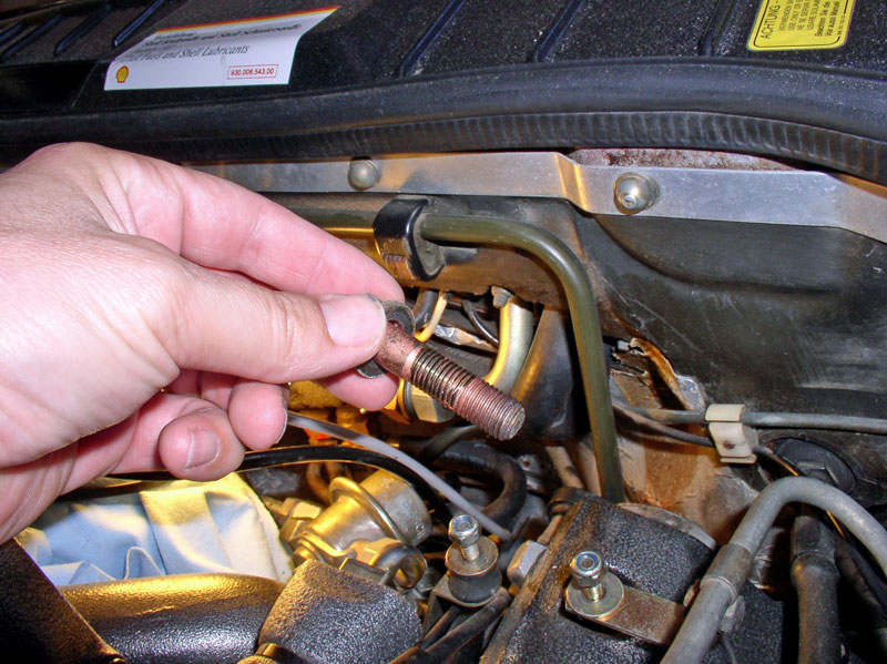
Now you can go top side and install the upper two 19mm Bell Housing-to-engine block bolts. My bolts had copper anti-size on them.
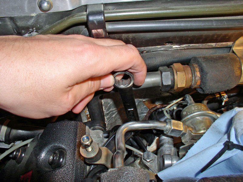
I used an extended, closed end 19mm wrench to tighten the bolts down. The driver�s side is pictured below. Make sure the wrench is fully seated on the bolt before applying the finishing torque. These bolts should be torqued to 77Nm or 56 ftlbs. Unfortunately, I could not fit a torque wrench down there so I used best guess taking into consideration the length of the wrench.
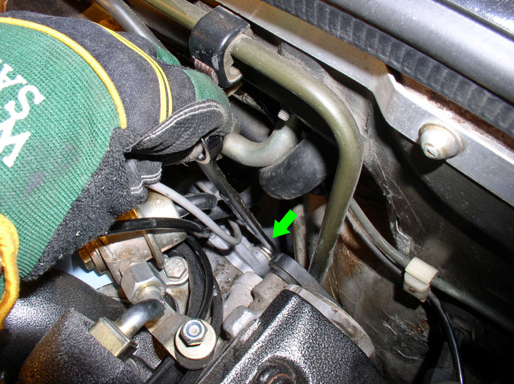
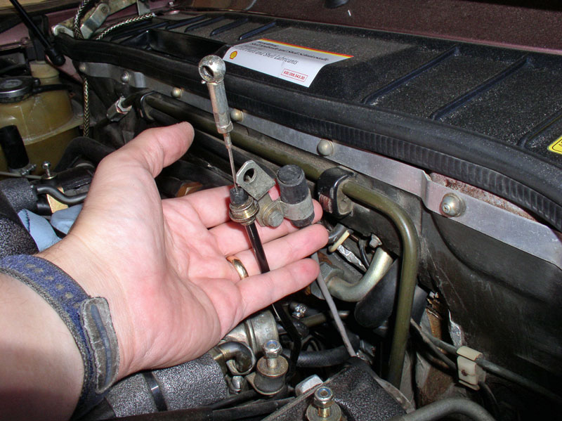
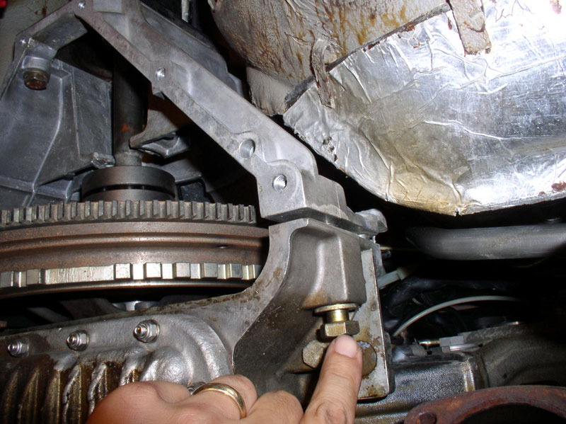
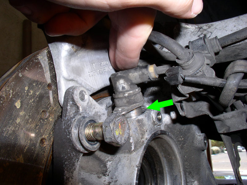
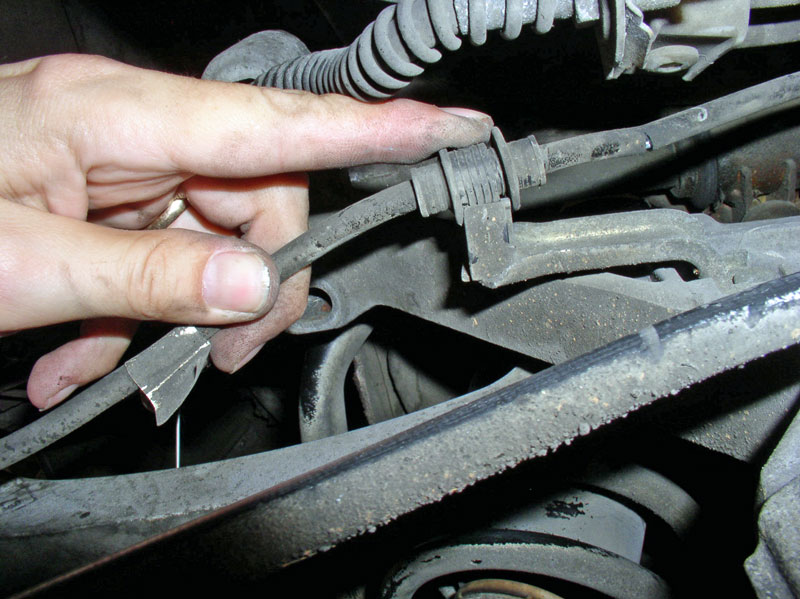
For the passenger side, I needed to disconnect the heater control valve hose from the engine block as pictured below in order to gain access to the bell housing bolt.
Once the heater control valve was tucked out of the way, I used the same wrench to install and torque down the passenger Bell Housing bolt.
When finished torquing down the two upper bolts, re-install the heater control valve hose and tighten the clamp.
Down below, torque the lower two 19mm Bell Housing-to-engine block bolts to 77Nm or 56 ftlbs.
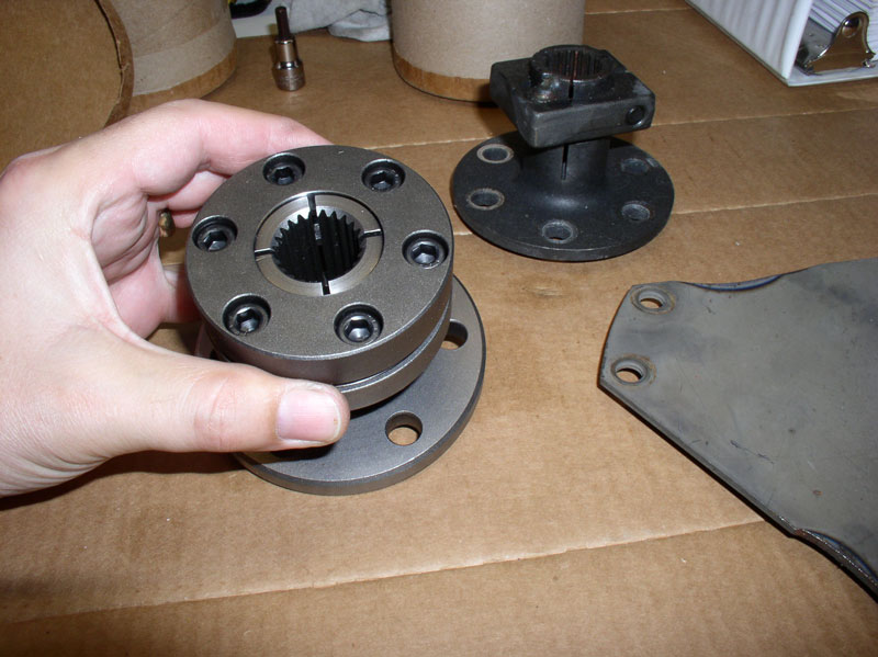
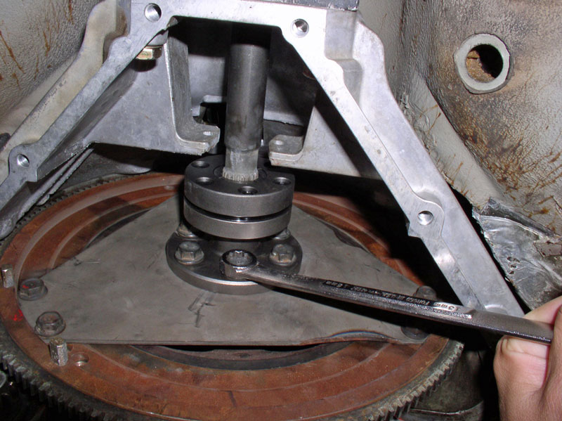
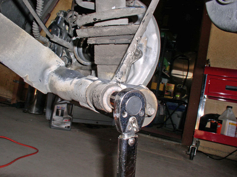
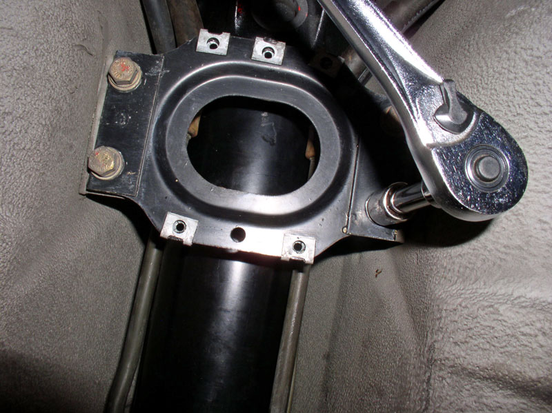
Next, I aligned the Super Clamp bolt holes with the flex plate threads and installed the 6 bolts. I installed all 6 bolts and hand tightened iniatially.
I then torqued all 6 bolts down. These bolts are 15mm bolts and should be torqued to 40-45 ftlbs. Unfortunately, I could not fit the torque wrench socket on the head of the bolts so I calibrated my arm for the correct torque value and used the long handle closed end 15mm wrench to torque the bottom 3 bolts first.
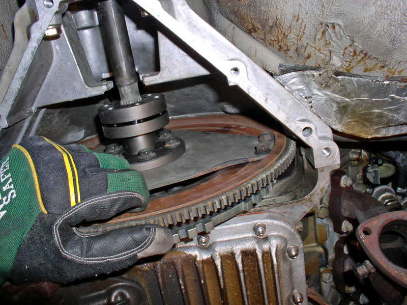
You will need to rotate the engine CLOCKWISE 180 degrees to get at the remaining 3 Super Clamp-to-Flex Plate bolts. I decided to go �Commando� and rotate the engine at the flywheel with my hand. If I were to do it �Rambo� style, I would have left the glove off. The default method of rotating the engine is to use a 27mm deep socket and long handle socket wrench to rotate the engine. Once you have the engine rotated, torque the remaining 3 bolts to spec.
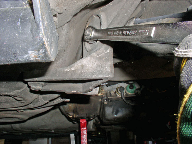
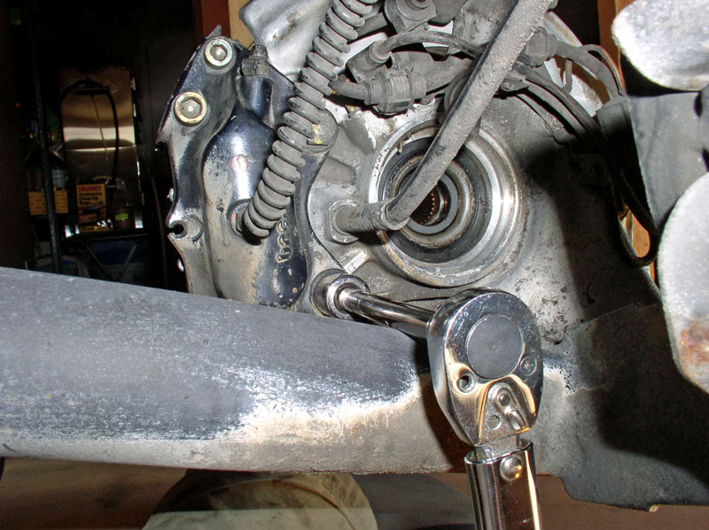
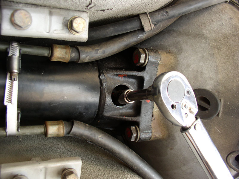
Install the upper two 17mm Bell Housing-to-TT bolts and begin torquing all 4 bolts. Torque to 45Nm or 33 ftlbs. Note: You can still see the transmission fluid cooler lines still wrapped in a plastic baggie at this point in the picture below. I decided to wait and clean the heat reflective wrap and reconnect the lines after the rear suspension was installed.
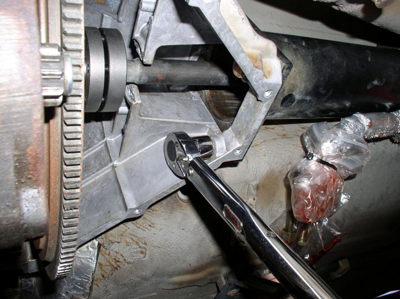
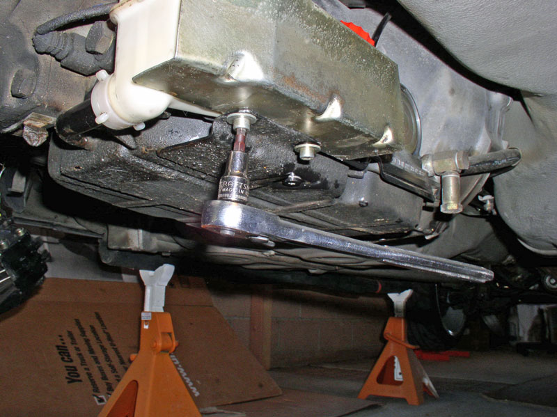
To gain access to the upper bolts, I used a 3 inch extension bar with the torque wrench as pictured below. At this point, the forward end of the TT is fully secured to the engine block and you should remove the floor jack and jack stand used to support the forward end of the TT. I did not torque down the Super Clamp yet � I decided it would be better to wait until the rear suspension was installed and everything locked down before final clamping of the drive shaft.
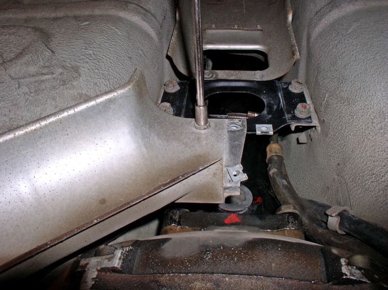
Moving back to the transmission, it is necessary to connect the gear selector linkage while the height of the transmission is still adjustable. Use the floor jack at the transmission to lower the transmission just enough to gain access to the shift selector linkage mounting bracket. This bracket takes two 6mm Allen Head bolts. Line up the bracket with its mounting threads on the transmission and tighten down the bolts.
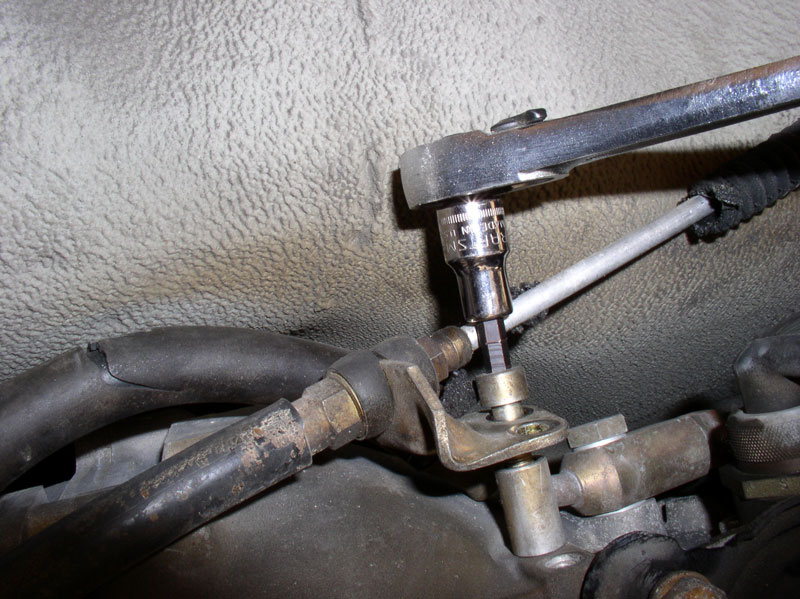
I lubricated the ball and the ball connector with a small amount of white grease then pressed the selector cable ball connector onto the shift arm of the transmission as pictured below. Mine was difficult to press on by hand given the tight spaces so I use a pair of pliers to assist.
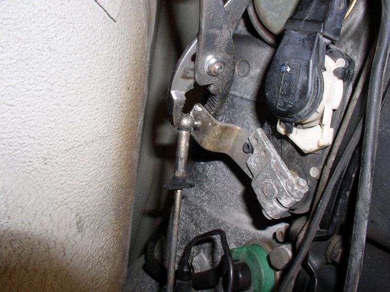
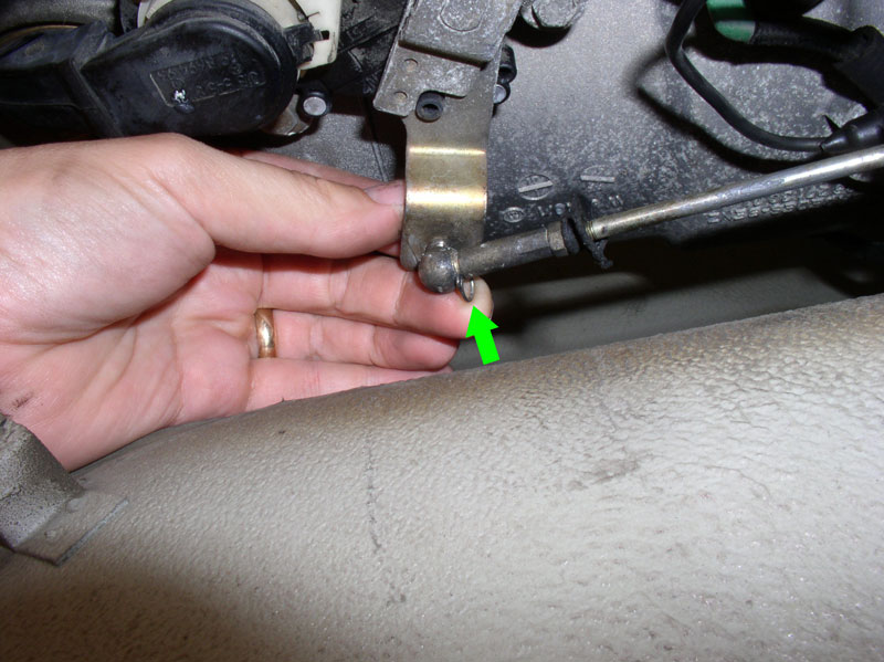
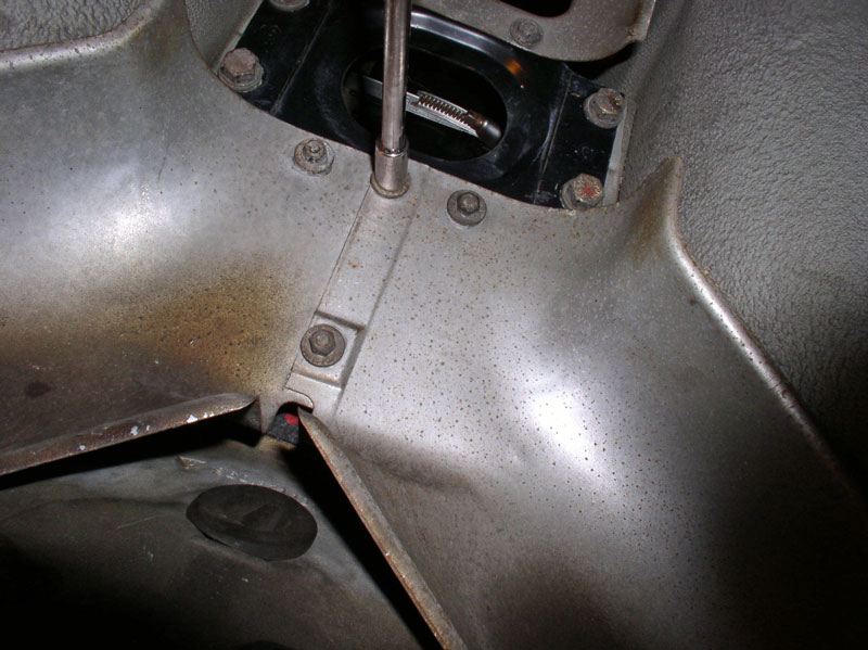
Finally, you will need to install the lock pin on the ball connector. The mounting hole for the pin is on the topside of the ball connector so I needed to �feel� for the hole blindly but when I found it, the pin slid in easily. Lock the pin in place by rotating it into its locked position around the base of the ball connector.
Continued....
Now you can go top side and install the upper two 19mm Bell Housing-to-engine block bolts. My bolts had copper anti-size on them.
I used an extended, closed end 19mm wrench to tighten the bolts down. The driver�s side is pictured below. Make sure the wrench is fully seated on the bolt before applying the finishing torque. These bolts should be torqued to 77Nm or 56 ftlbs. Unfortunately, I could not fit a torque wrench down there so I used best guess taking into consideration the length of the wrench.
For the passenger side, I needed to disconnect the heater control valve hose from the engine block as pictured below in order to gain access to the bell housing bolt.
Once the heater control valve was tucked out of the way, I used the same wrench to install and torque down the passenger Bell Housing bolt.
When finished torquing down the two upper bolts, re-install the heater control valve hose and tighten the clamp.
Down below, torque the lower two 19mm Bell Housing-to-engine block bolts to 77Nm or 56 ftlbs.
Next, I aligned the Super Clamp bolt holes with the flex plate threads and installed the 6 bolts. I installed all 6 bolts and hand tightened iniatially.
I then torqued all 6 bolts down. These bolts are 15mm bolts and should be torqued to 40-45 ftlbs. Unfortunately, I could not fit the torque wrench socket on the head of the bolts so I calibrated my arm for the correct torque value and used the long handle closed end 15mm wrench to torque the bottom 3 bolts first.
You will need to rotate the engine CLOCKWISE 180 degrees to get at the remaining 3 Super Clamp-to-Flex Plate bolts. I decided to go �Commando� and rotate the engine at the flywheel with my hand. If I were to do it �Rambo� style, I would have left the glove off. The default method of rotating the engine is to use a 27mm deep socket and long handle socket wrench to rotate the engine. Once you have the engine rotated, torque the remaining 3 bolts to spec.
Install the upper two 17mm Bell Housing-to-TT bolts and begin torquing all 4 bolts. Torque to 45Nm or 33 ftlbs. Note: You can still see the transmission fluid cooler lines still wrapped in a plastic baggie at this point in the picture below. I decided to wait and clean the heat reflective wrap and reconnect the lines after the rear suspension was installed.
To gain access to the upper bolts, I used a 3 inch extension bar with the torque wrench as pictured below. At this point, the forward end of the TT is fully secured to the engine block and you should remove the floor jack and jack stand used to support the forward end of the TT. I did not torque down the Super Clamp yet � I decided it would be better to wait until the rear suspension was installed and everything locked down before final clamping of the drive shaft.
Moving back to the transmission, it is necessary to connect the gear selector linkage while the height of the transmission is still adjustable. Use the floor jack at the transmission to lower the transmission just enough to gain access to the shift selector linkage mounting bracket. This bracket takes two 6mm Allen Head bolts. Line up the bracket with its mounting threads on the transmission and tighten down the bolts.
I lubricated the ball and the ball connector with a small amount of white grease then pressed the selector cable ball connector onto the shift arm of the transmission as pictured below. Mine was difficult to press on by hand given the tight spaces so I use a pair of pliers to assist.
Finally, you will need to install the lock pin on the ball connector. The mounting hole for the pin is on the topside of the ball connector so I needed to �feel� for the hole blindly but when I found it, the pin slid in easily. Lock the pin in place by rotating it into its locked position around the base of the ball connector.
Continued....
12-19-2010, 11:05 PM
#49
Three Wheelin'
Thread Starter
Join Date: Sep 2007
Location: Ridgecrest, California
Posts: 1,363
Likes: 0
Received 148 Likes
on
32 Posts
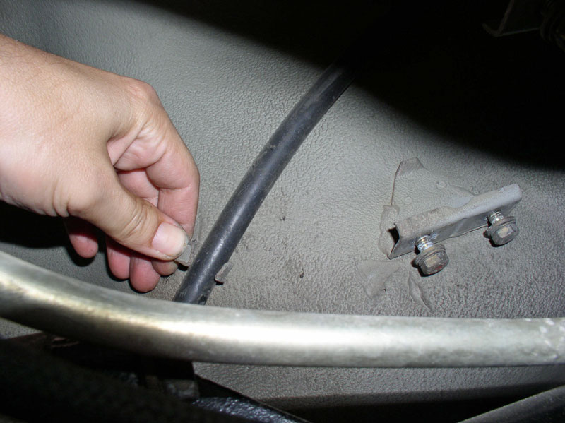
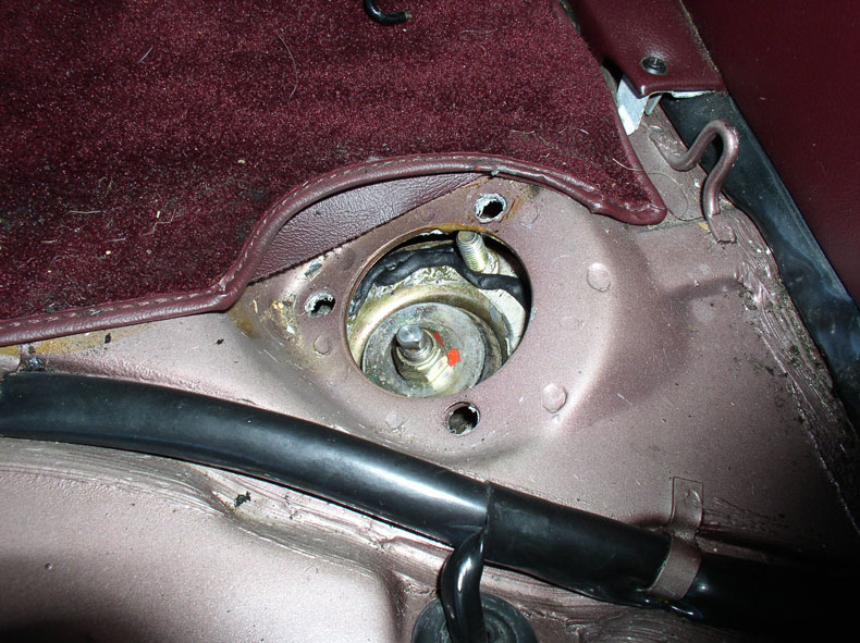
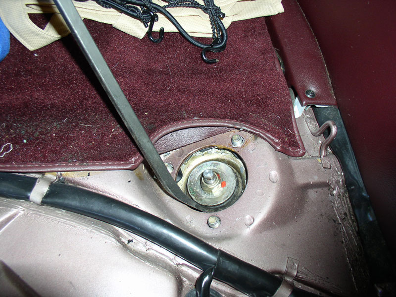
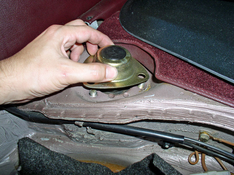
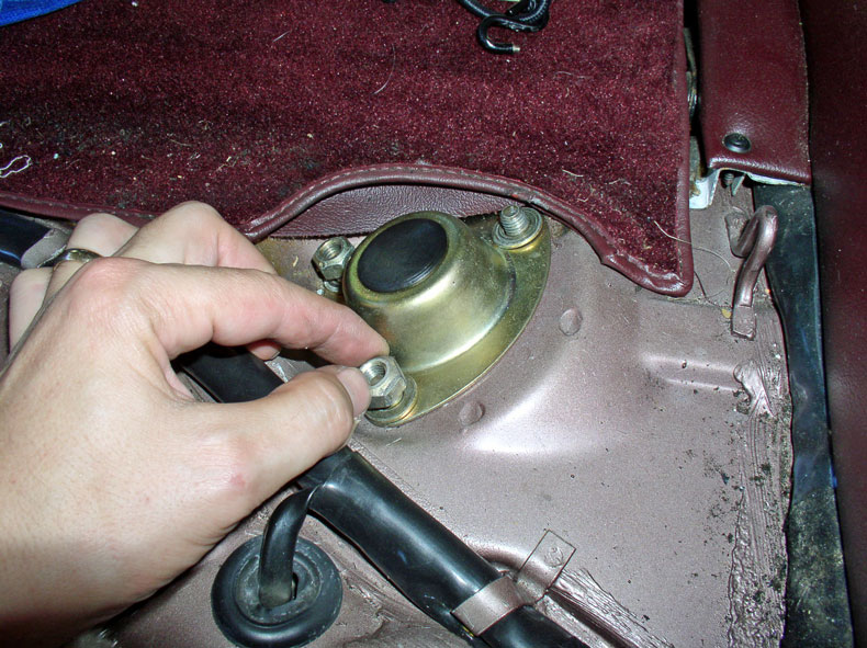
Before raising the transmission to its final height, secure the shift selector cable to the car body by wrapping the cable housing in the flexible holder as shown below.
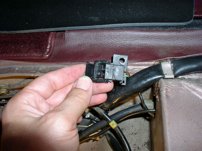
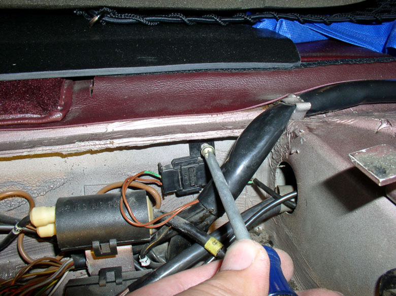
Next, raise the transmission to its highest position making sure nothing is snagged or hung up. From the spare tire compartment, pull as much of the transmission harness through the access port as needed to reconnect the wiring connectors. I first re-connected the small black connector as shown.
Then mounted the connector to the car body with the Phillips screw as shown.
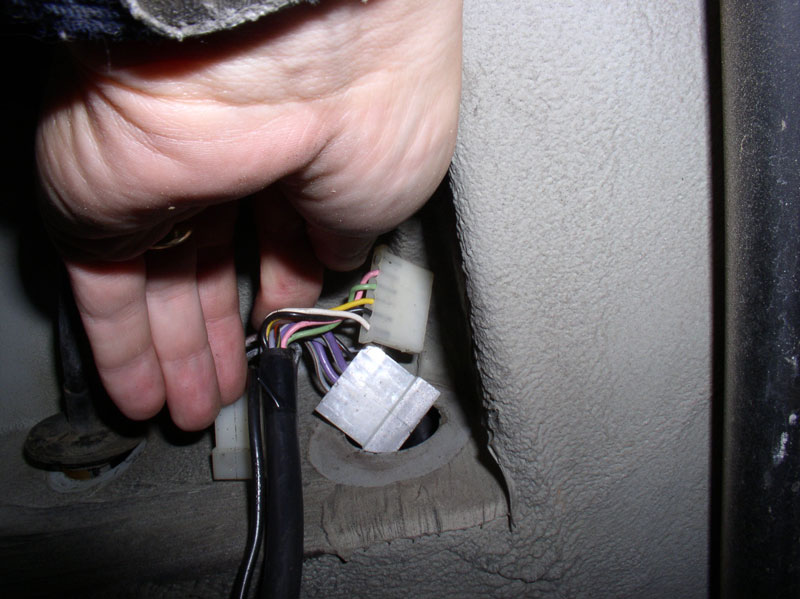
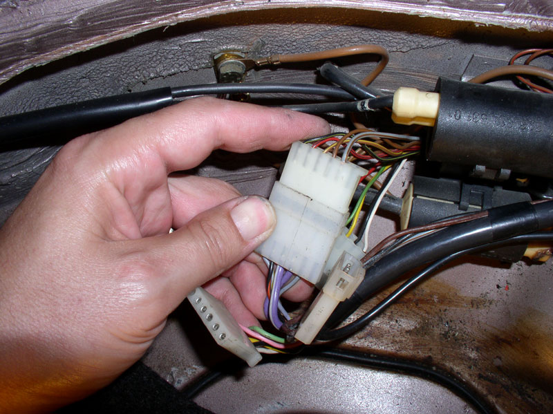
I then re-connected the 3 white plastic connectors. Each is a different size and/or keyed so that they can�t be connected improperly.
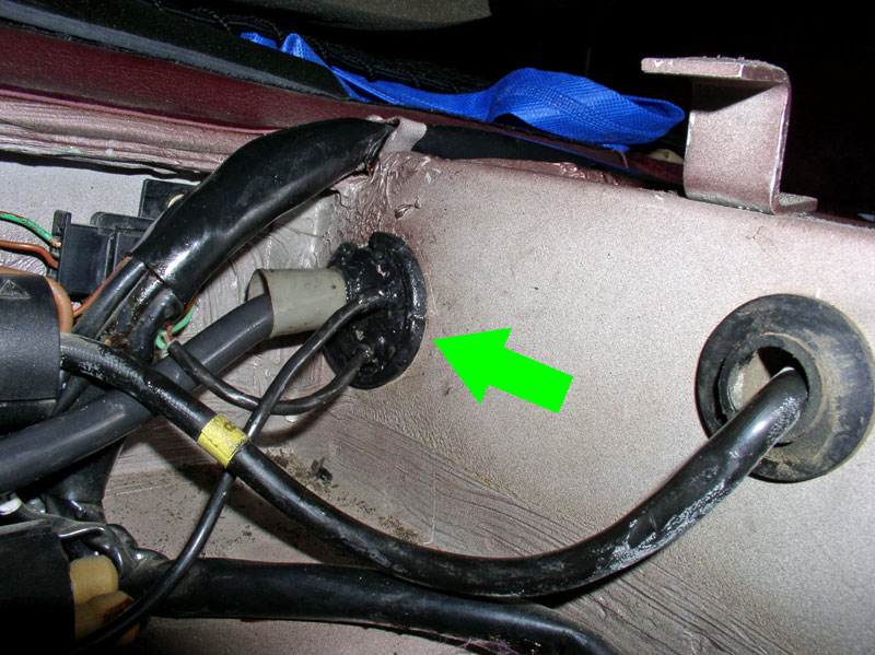
Re-install the rubber grommet seal on the access hole. I found coating the grommet with the spare �personnel lubricant� or silicone lubricant helped seat the grommet on the access port.
I needed to remove the floor jack and wooden transmission platform and suspend the transmission with straps in preparation for the next phase � installation of the rear suspension. I used the same ratcheting tie down straps used when removing the transmission. Others have also used chains. I secured the ends of the strap to the �dip� in the rear sway bar as shown.
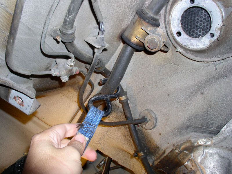
And ensured the strap was positioned between the ribs of the differential casing as shown in the picture below. This keeps the strap (or chains) out of the way while installing the rear suspension and also helps support the transmission more securely/safely so the strap (or chains) don�t move while working. Place a Jack Stand at the rear of the TT or under the TC housing to additional safety. Remove the floor jack supporting the transmission. Installing the rear suspension is next.
Next, raise the transmission to its highest position making sure nothing is snagged or hung up. From the spare tire compartment, pull as much of the transmission harness through the access port as needed to reconnect the wiring connectors. I first re-connected the small black connector as shown.
Then mounted the connector to the car body with the Phillips screw as shown.
I then re-connected the 3 white plastic connectors. Each is a different size and/or keyed so that they can�t be connected improperly.
Re-install the rubber grommet seal on the access hole. I found coating the grommet with the spare �personnel lubricant� or silicone lubricant helped seat the grommet on the access port.
I needed to remove the floor jack and wooden transmission platform and suspend the transmission with straps in preparation for the next phase � installation of the rear suspension. I used the same ratcheting tie down straps used when removing the transmission. Others have also used chains. I secured the ends of the strap to the �dip� in the rear sway bar as shown.
And ensured the strap was positioned between the ribs of the differential casing as shown in the picture below. This keeps the strap (or chains) out of the way while installing the rear suspension and also helps support the transmission more securely/safely so the strap (or chains) don�t move while working. Place a Jack Stand at the rear of the TT or under the TC housing to additional safety. Remove the floor jack supporting the transmission. Installing the rear suspension is next.
 12-20-2010, 03:56 AM
#51
Nordschleife Master
Dwayne - for situations like that, I've found a crowsfoot extension on the torque wrench affords much better access, as you don't need the space to get a socket in there. Its like an open-ended spanner which fits onto the drive (3/8 in the case of my set) and can sneak into areas without much clearance.
Just work out the correct torque value taking into account the additional length added to the end of the wrench by the crowsfoot.
Just work out the correct torque value taking into account the additional length added to the end of the wrench by the crowsfoot.
12-20-2010, 06:59 AM
#52
Three Wheelin'
Join Date: Sep 2003
Location: SF Bay Area
Posts: 1,526
Likes: 0
Received 0 Likes
on
0 Posts
What are you a masochist. My time is valuable - Cut the bell housing it will not hurt your car. You may have bad dreams but you will have more time to sleep.
You should pull the torque converter and front pump. This can be down with the transmission in the car. This is recommended by Mercedes. Replace the torque bearings - about $4 each, the front seal and the oil pump O ring. If either flex plate has rivets they should be replaced by bolts. A port a power is instrumental in removal of the torque bearings.
Here are some pictures
http://www.kondratyev.com/porsche/te...orque_tube.htm
The job is sure a lot easier on the tilter.
12-20-2010, 07:15 AM
#53
Former Vendor

Join Date: Feb 2004
Posts: 2,139
Likes: 0
Received 0 Likes
on
0 Posts
That is great Dwayne, I never knew that the SuperBearings were made to be serviced, not that i can imagine ever wearing one out.
the bearings are not only bigger, but have a higher speed and temp ratings than the originals.
I tell people that they sell them self, all they have to do is hold a stock one in one hand and a SuperBearing in the other, and they will know.
the bearings are not only bigger, but have a higher speed and temp ratings than the originals.
I tell people that they sell them self, all they have to do is hold a stock one in one hand and a SuperBearing in the other, and they will know.
First off it was a pleasure working with Dwayne on this project. I trusted him to be able to show the Super Bearing servicing since we both thought it would be a neat addition to his overall write-up. This thread gives a lot of information to the rest of the community and should be tabbed as a "favorite" for anyone contemplating doing a 928 TT and Transmission R&R. Thanks Dwayne!
Greg, when we designed these Super Bearings it was with the intent of being able to rebuild them in the future if needed. I really appreciate your comments about them and even more so since you've installed them yourself at your shop.
Cheers,
12-20-2010, 09:36 AM
#54
Three Wheelin'
Thread Starter
Join Date: Sep 2007
Location: Ridgecrest, California
Posts: 1,363
Likes: 0
Received 148 Likes
on
32 Posts
CH15 INSTALLING REAR SUSPENSION
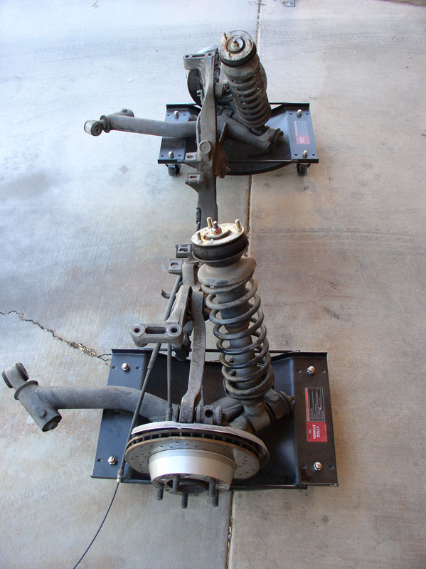
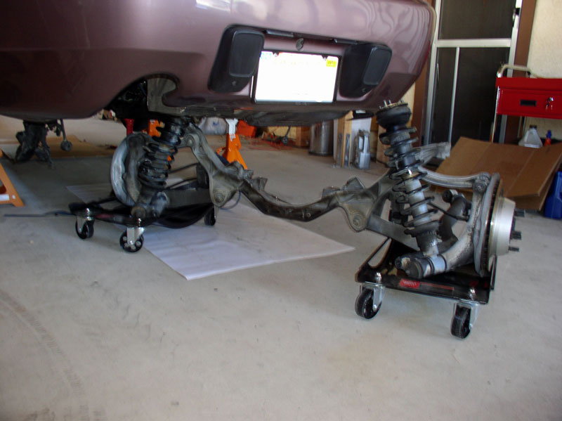
Before re-installing the rear suspension, I cleaned it off a bit (not a detailed cleaning, though) to remove the loose dirt and grime. I used some citrus cleaner degreaser and a nylon brush and water. Using the car dollies, made it very easy to maneuver the assembly.
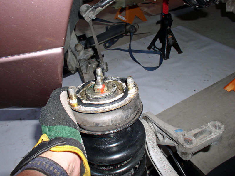
Since the white sealant at the top of the spring towers had wore away, I used some black non-hardening automotive sealant from 3M I purchased from a Car Quest auto parts store in town.
After installation, I found a single cord (as shown below) was too much and resulted in the excess sealant oozing out. I would recommend about half the amount shown below. In other words, break the cord in half and roll it out so it�s long enough to go around the top of the spring tower.
I observed the rear wheel speed sensor was caked with dirt so cleaned it off.
The picture below is what it should look like when cleaned off.
Since the car is not raised high enough to simply roll the rear suspension under the car, I needed to maneuver it around to clear the rear bumper cover. I nestled the driver�s side shock and spring in between the differential and battery compartment as shown below.
I then swung the passenger side shock and spring around the rear of the bumper cover toward the passenger side rear wheel well.
When you come to the trailing edge of the wheel well, you will need to pull the spring tower outward (toward you) in order to get it to clear the car body. It�s also a good idea to cover the top of the spring tower with a towel in order to protect the paint in case it gets away form you.
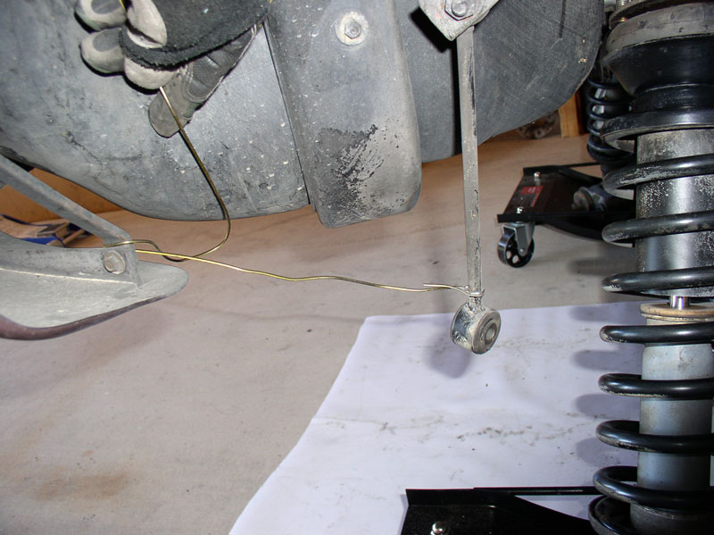
With the rear suspension now under the car, I tied back the drop links with some wire to keep them from interfering with the installation. You can also remove the link all together by removing the nut/bolt at the top of the link where it�s connected to the rear stabilizer bar.
I inserted the floor jack under the center of the cross-member and used the floor jack to raise the suspension into position. Once the suspension is raised enough to clear the car dollies, you can remove the car dollies.
I raised the suspension a few inches at a time checking for snags and hang ups. As you raise the suspension with the floor jack, guide both the spring towers into their mounting recesses in the body as shown in the picture below.
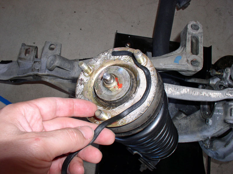
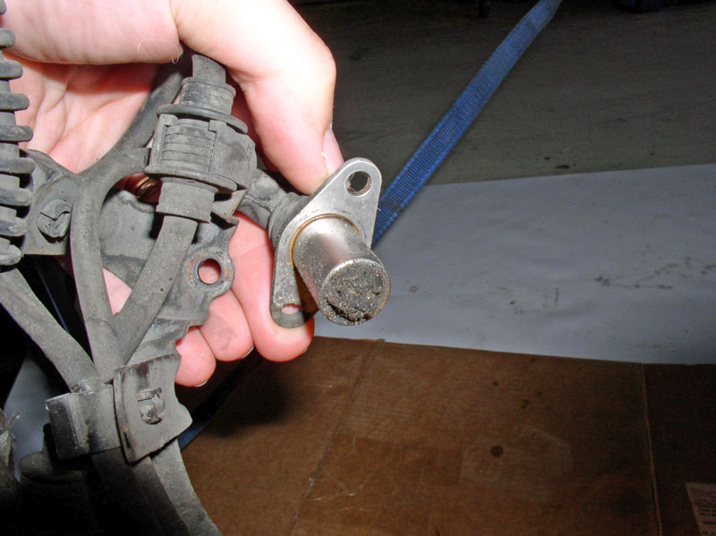
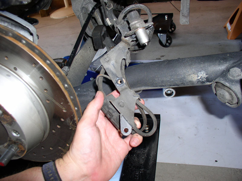
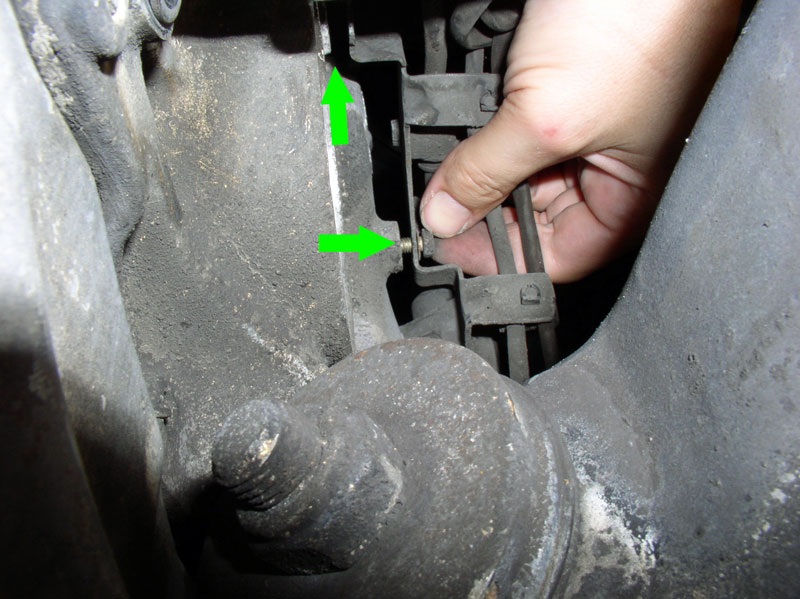
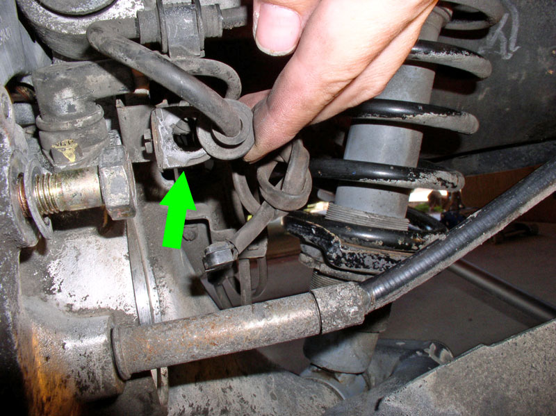
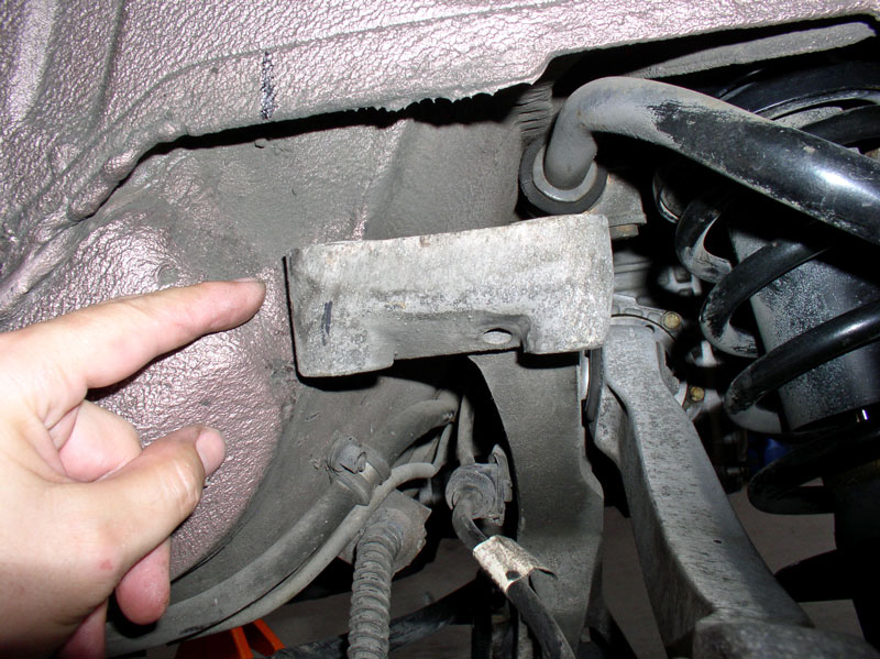
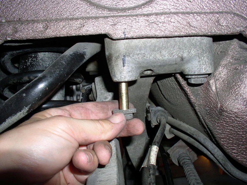
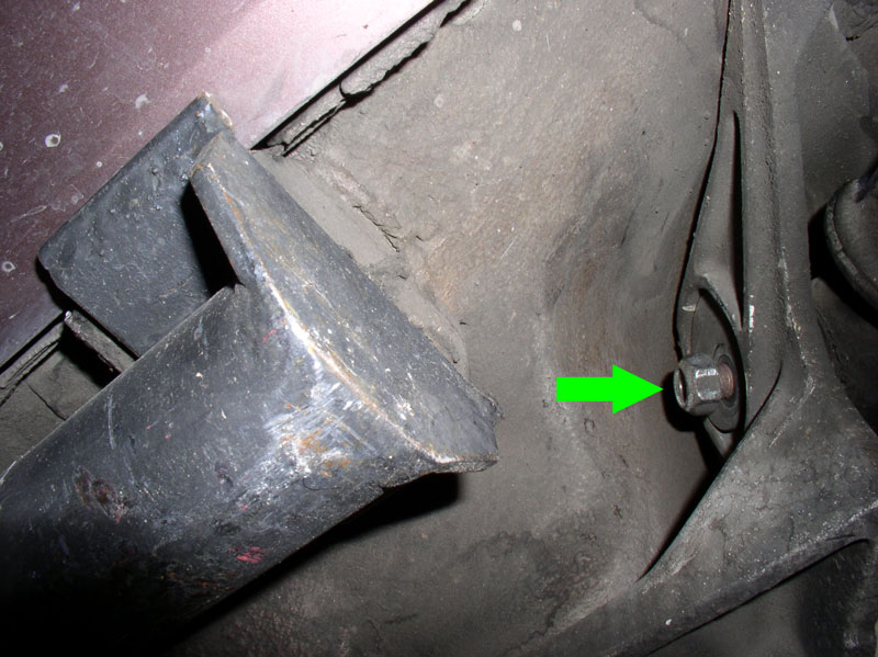
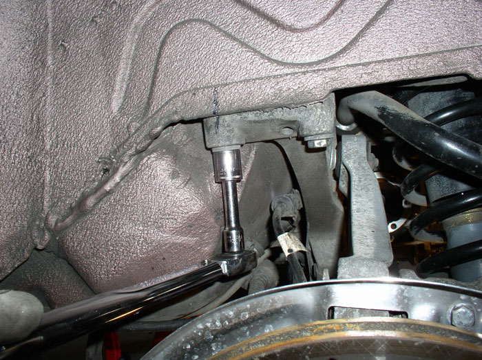
After the transmission had been raised at lease 6 inches, I worked on re-installing the brake electrical bracket shown in the picture below. I found it easier to install this bracket when the suspension was about mid-way up as it provided enough clearance above and below the wheel to work.
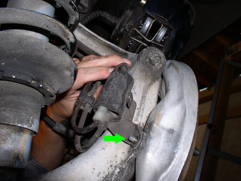
To re-install the bracket, you will need to re-install the speed sensor and two bolts and a nut to secure the bracket to the backside of the wheel hub carrier. Press the speed sensor into is mounting hole as shown. Line up the hole in the mounting bracket with the threads in the hub carrier. Press the sensor all the way down until it is fully seated.
Place the rearward mount of the bracket over the brake dust shield stud as shown below.
Install the center bolt for the bracket. It�s a 10mm hex bolt. The upper bolt is installed in the upper end of the bracket as shown by the upper arrow below.
Continued....
Before re-installing the rear suspension, I cleaned it off a bit (not a detailed cleaning, though) to remove the loose dirt and grime. I used some citrus cleaner degreaser and a nylon brush and water. Using the car dollies, made it very easy to maneuver the assembly.
Since the white sealant at the top of the spring towers had wore away, I used some black non-hardening automotive sealant from 3M I purchased from a Car Quest auto parts store in town.
After installation, I found a single cord (as shown below) was too much and resulted in the excess sealant oozing out. I would recommend about half the amount shown below. In other words, break the cord in half and roll it out so it�s long enough to go around the top of the spring tower.
I observed the rear wheel speed sensor was caked with dirt so cleaned it off.
The picture below is what it should look like when cleaned off.
Since the car is not raised high enough to simply roll the rear suspension under the car, I needed to maneuver it around to clear the rear bumper cover. I nestled the driver�s side shock and spring in between the differential and battery compartment as shown below.
I then swung the passenger side shock and spring around the rear of the bumper cover toward the passenger side rear wheel well.
When you come to the trailing edge of the wheel well, you will need to pull the spring tower outward (toward you) in order to get it to clear the car body. It�s also a good idea to cover the top of the spring tower with a towel in order to protect the paint in case it gets away form you.
With the rear suspension now under the car, I tied back the drop links with some wire to keep them from interfering with the installation. You can also remove the link all together by removing the nut/bolt at the top of the link where it�s connected to the rear stabilizer bar.
I inserted the floor jack under the center of the cross-member and used the floor jack to raise the suspension into position. Once the suspension is raised enough to clear the car dollies, you can remove the car dollies.
I raised the suspension a few inches at a time checking for snags and hang ups. As you raise the suspension with the floor jack, guide both the spring towers into their mounting recesses in the body as shown in the picture below.
After the transmission had been raised at lease 6 inches, I worked on re-installing the brake electrical bracket shown in the picture below. I found it easier to install this bracket when the suspension was about mid-way up as it provided enough clearance above and below the wheel to work.
To re-install the bracket, you will need to re-install the speed sensor and two bolts and a nut to secure the bracket to the backside of the wheel hub carrier. Press the speed sensor into is mounting hole as shown. Line up the hole in the mounting bracket with the threads in the hub carrier. Press the sensor all the way down until it is fully seated.
Place the rearward mount of the bracket over the brake dust shield stud as shown below.
Install the center bolt for the bracket. It�s a 10mm hex bolt. The upper bolt is installed in the upper end of the bracket as shown by the upper arrow below.
Continued....
12-20-2010, 09:55 AM
#55
Three Wheelin'
Thread Starter
Join Date: Sep 2007
Location: Ridgecrest, California
Posts: 1,363
Likes: 0
Received 148 Likes
on
32 Posts
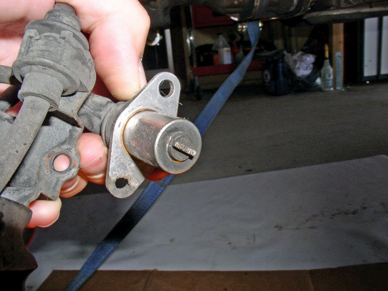
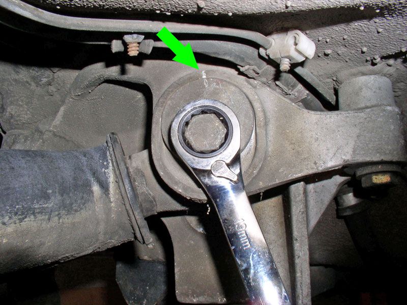
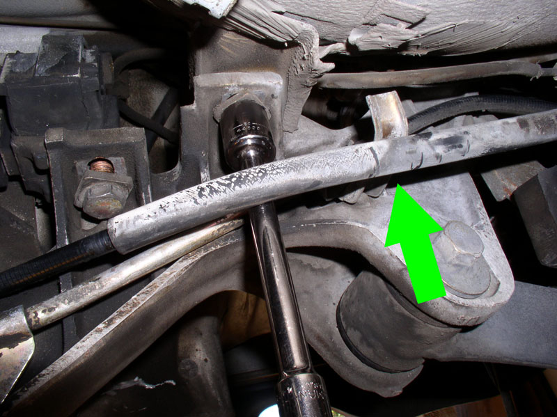
Tighten both the upper 10mm bolt and the center 10mm bolt to 10Nm or 7 ftlbs as identified by the green arrows in the picture below.
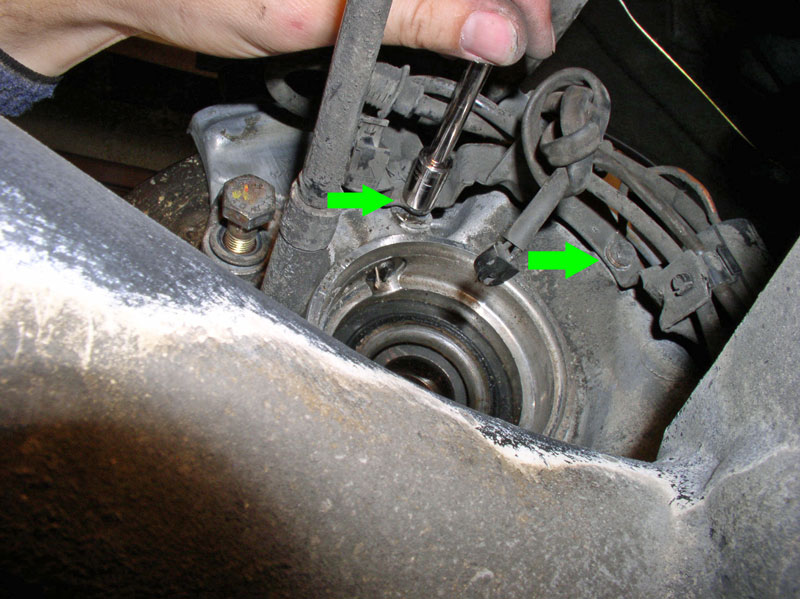
Install the 10mm nut on the dust shield stud and tighten as shown below.
Install and tighten the 5mm Allen Head bolt that secures the speed sensor to 10Nm or 7 ftlbs as shown below.
Re-install the wiring harnesses into the respective holders for any wiring harnesses that were removed earlier.
Here�s a second harness I re-connected at the cross member. When finished, repeat the same steps for the bracket and harness for the other rear wheel.
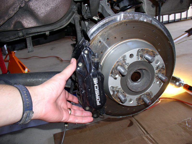
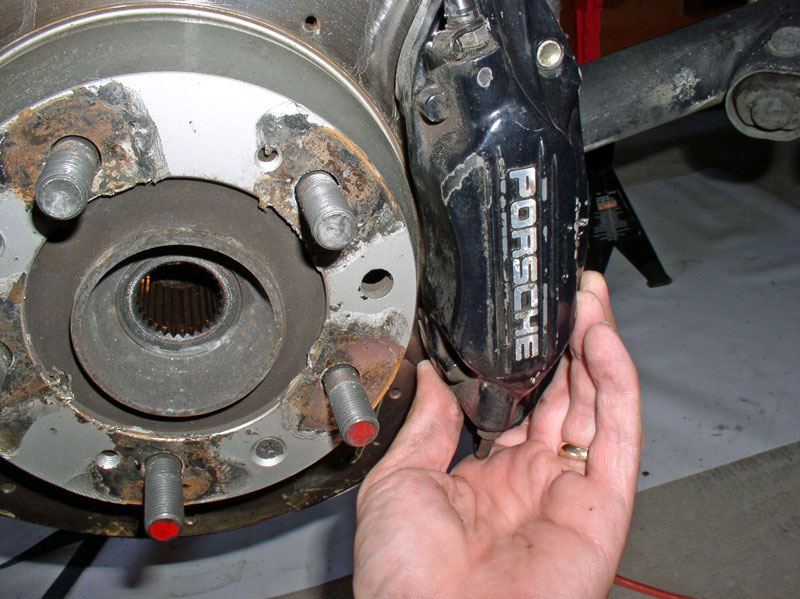
On the driver�s side, I removed the brake caliper from the wire hanger since it was going to be in the way when I raised the suspension. I installed it on the wheel and installed the two 19mm bolts and hand tightened them to hold the caliper in place.
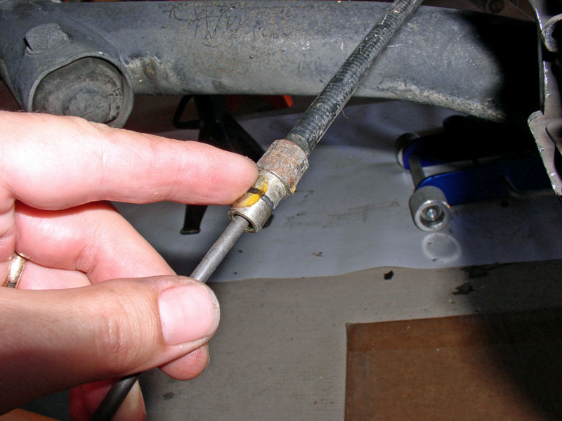
I then prepared to re-insert the emergency brake cable into the cabin access port. Before installing, however, I applied a small amount of silicone lubricant to the o-ring to ease the installation and help the o-ring to stay seated when installing.
Start feeding the end of the cable through the access port�.
�. until you press in the cable housing end with the o-ring into the access port. Push it in until it is fully seated as pictured below.
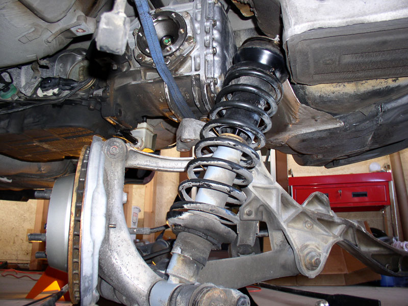
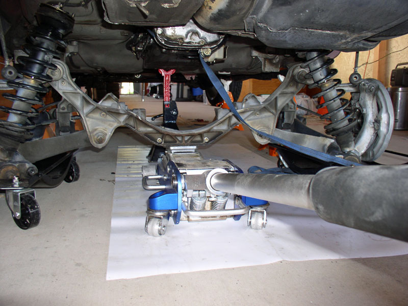
I continued raising the suspension with the floor jack. I raised the suspension a couple of inches at a time and closely monitored the outer cross member-to-body mounting (pictured below) to make sure it was not getting hung up on the under body coating. It is easy to crank up the floor jack and if the outer mountings are pressed up against the body, it can scrape off the under body coating. If it�s touching, just pull it away from the body before continuing to lift.
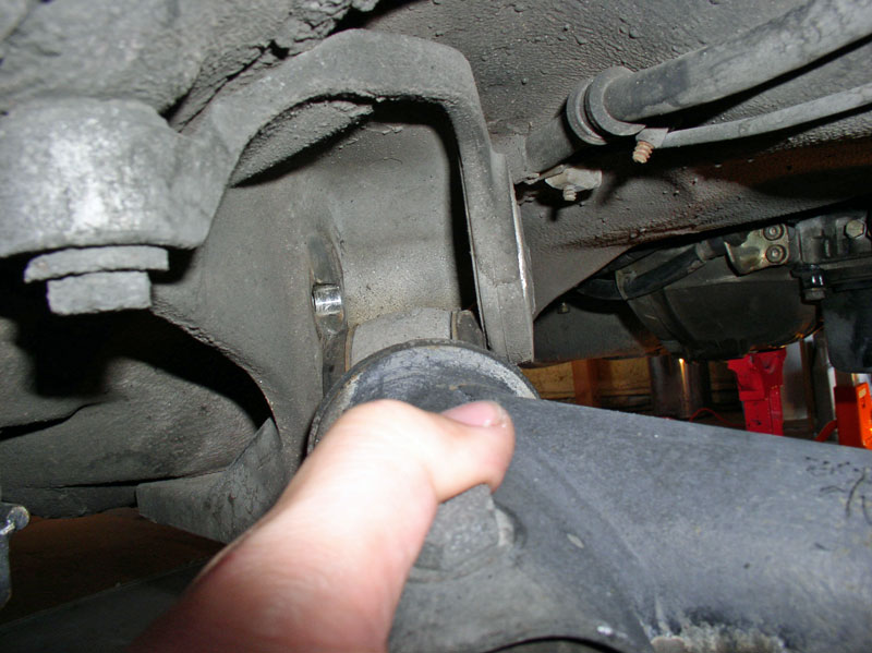
As you continue to lift the suspension, guide the lower control arm into its receiving bracket as shown. It should be a snug fit so give it a firm push. I did not use any percussion instruments (hammers), just grasp the control arm and push.
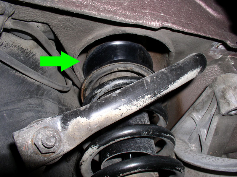
When the spring towers reach their seat as seen from the rear hatch area, you may notice the studs are not aligned with the mounting holes as pictured below.
You can use a pry bar or large screwdriver to pry the center of the spring tower to maneuver it into its mounting holes as shown in the picture below.
Continue to lift the suspension until enough threads are visible to install the covers and bolts. The cover mounting holes are not uniformly spaced so they will only fit on the threads one way.
Install the 17mm bolts and their washers on the studs as shown and hand tighten. They will be torqued to spec later.
Continued....
Install the 10mm nut on the dust shield stud and tighten as shown below.
Install and tighten the 5mm Allen Head bolt that secures the speed sensor to 10Nm or 7 ftlbs as shown below.
Re-install the wiring harnesses into the respective holders for any wiring harnesses that were removed earlier.
Here�s a second harness I re-connected at the cross member. When finished, repeat the same steps for the bracket and harness for the other rear wheel.
On the driver�s side, I removed the brake caliper from the wire hanger since it was going to be in the way when I raised the suspension. I installed it on the wheel and installed the two 19mm bolts and hand tightened them to hold the caliper in place.
I then prepared to re-insert the emergency brake cable into the cabin access port. Before installing, however, I applied a small amount of silicone lubricant to the o-ring to ease the installation and help the o-ring to stay seated when installing.
Start feeding the end of the cable through the access port�.
�. until you press in the cable housing end with the o-ring into the access port. Push it in until it is fully seated as pictured below.
I continued raising the suspension with the floor jack. I raised the suspension a couple of inches at a time and closely monitored the outer cross member-to-body mounting (pictured below) to make sure it was not getting hung up on the under body coating. It is easy to crank up the floor jack and if the outer mountings are pressed up against the body, it can scrape off the under body coating. If it�s touching, just pull it away from the body before continuing to lift.
As you continue to lift the suspension, guide the lower control arm into its receiving bracket as shown. It should be a snug fit so give it a firm push. I did not use any percussion instruments (hammers), just grasp the control arm and push.
When the spring towers reach their seat as seen from the rear hatch area, you may notice the studs are not aligned with the mounting holes as pictured below.
You can use a pry bar or large screwdriver to pry the center of the spring tower to maneuver it into its mounting holes as shown in the picture below.
Continue to lift the suspension until enough threads are visible to install the covers and bolts. The cover mounting holes are not uniformly spaced so they will only fit on the threads one way.
Install the 17mm bolts and their washers on the studs as shown and hand tighten. They will be torqued to spec later.
Continued....
12-20-2010, 10:53 AM
#56
Three Wheelin'
Thread Starter
Join Date: Sep 2007
Location: Ridgecrest, California
Posts: 1,363
Likes: 0
Received 148 Likes
on
32 Posts
I then mounted the passenger side brake caliper and installed the two 19mm bolts and hand tightened them to hold it in place. The bolts will be torqued to spec later.
The marks made earlier should line up on the outer cross member mounting (see below). Install the two 17mm bolts that secure the cross member to the wheel well as shown below. I ensured the marks lined up and snugged the bolts down. They will be torqued to spec later.
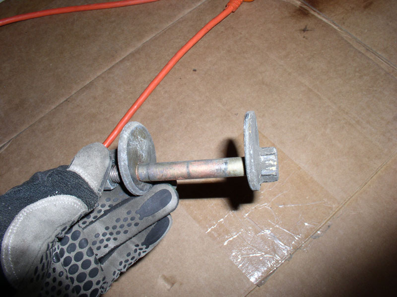
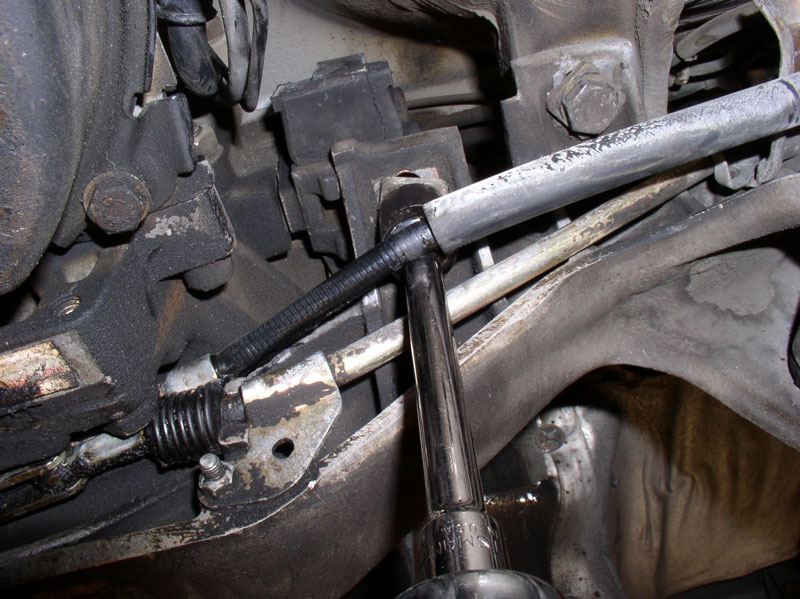
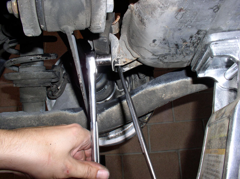
Next, I installed the lower control arm alignment bolt and washer. The washer mounted on the end with the nut is installed with the beveled edge facing inward as pictured below.
Press the bolt through the mounting bracket and through the control arm bushing until it is fully seated as shown in the picture below.
Install the washer and locknut on the opposite side as shown below. The bolt and washer are keyed to fit together only one way. You may lightly snug the nut down but do not tighten yet because the control arm must be adjusted to the same position before it was removed.
Using a 19mm wrench, turn the adjusting bolt until the alignment marks made earlier (before removal) are lined up.
Then, tighten the 19mm nut on the forward facing side to 120Nm or 88 ftlbs while counter-holding the adjusting bolt on the opposite side. Repeat for the other wheel.
Next, I torqued the 17mm bolts that secure the cross member to the body to 46Nm or 33 ftlbs. Torque both bolts on both sides of the car.
Then torque the spring tower 17mm lock nuts inside the cargo hatch area to 46Nm or 33 ftlbs. Tighten all 6 nuts � three on each tower.
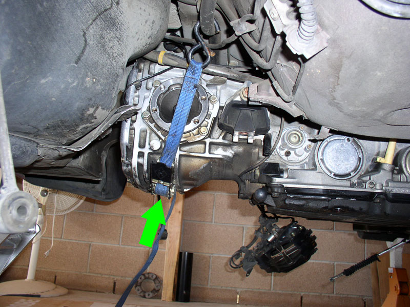
At this point, the cross member is secured to the body and we can release the strap or chains that suspend the transmission. Releasing the transmission will allow it to rest on the cross member which is needed before we can secure it with bolts.
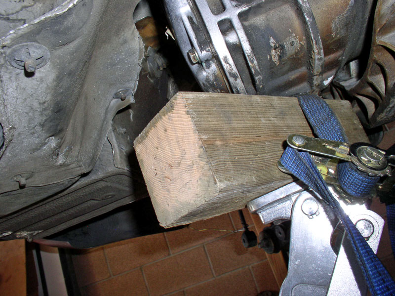
I positioned a scrap 4 X 4 on the floor jack and lifted the transmission at the differential. I lifted just enough to loosen and remove the lifting strap.
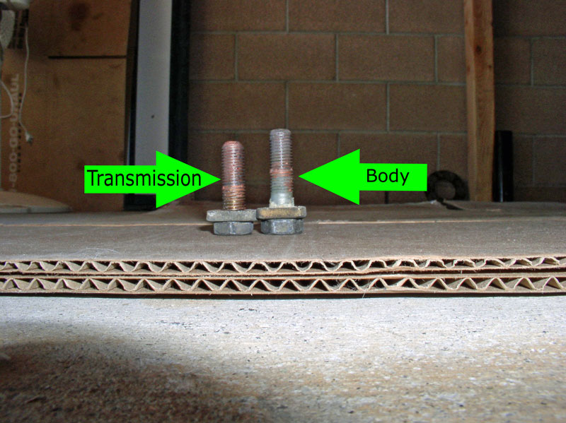
Now the transmission can be secured to the cross member. There are two 19mm bolts on either side of the transmission to install. The shorter of the two secures the transmission to the cross member at the transmission mount bracket. The longer of the two secures the cross member to the underside of the body.
Pictured below is the driver�s side mounting for these two bolts. The bolt on the left is the shorter bolt for the transmission. You can lift and remove the emergency brake cable from its holder to allow easier access to the two bolts for tightening. Torque down the cross member to body 19mm bolt to 85Nm or 60 ftlbs.
Tighten the transmission to cross member 19mm bolt also to 85Nm or 60 ftlbs.
Place the emergency brake cable back into its holder. Then install and tighten the same two bolts for the other side of the transmission.
Continued....
The marks made earlier should line up on the outer cross member mounting (see below). Install the two 17mm bolts that secure the cross member to the wheel well as shown below. I ensured the marks lined up and snugged the bolts down. They will be torqued to spec later.
Next, I installed the lower control arm alignment bolt and washer. The washer mounted on the end with the nut is installed with the beveled edge facing inward as pictured below.
Press the bolt through the mounting bracket and through the control arm bushing until it is fully seated as shown in the picture below.
Install the washer and locknut on the opposite side as shown below. The bolt and washer are keyed to fit together only one way. You may lightly snug the nut down but do not tighten yet because the control arm must be adjusted to the same position before it was removed.
Using a 19mm wrench, turn the adjusting bolt until the alignment marks made earlier (before removal) are lined up.
Then, tighten the 19mm nut on the forward facing side to 120Nm or 88 ftlbs while counter-holding the adjusting bolt on the opposite side. Repeat for the other wheel.
Next, I torqued the 17mm bolts that secure the cross member to the body to 46Nm or 33 ftlbs. Torque both bolts on both sides of the car.
Then torque the spring tower 17mm lock nuts inside the cargo hatch area to 46Nm or 33 ftlbs. Tighten all 6 nuts � three on each tower.
At this point, the cross member is secured to the body and we can release the strap or chains that suspend the transmission. Releasing the transmission will allow it to rest on the cross member which is needed before we can secure it with bolts.
I positioned a scrap 4 X 4 on the floor jack and lifted the transmission at the differential. I lifted just enough to loosen and remove the lifting strap.
Now the transmission can be secured to the cross member. There are two 19mm bolts on either side of the transmission to install. The shorter of the two secures the transmission to the cross member at the transmission mount bracket. The longer of the two secures the cross member to the underside of the body.
Pictured below is the driver�s side mounting for these two bolts. The bolt on the left is the shorter bolt for the transmission. You can lift and remove the emergency brake cable from its holder to allow easier access to the two bolts for tightening. Torque down the cross member to body 19mm bolt to 85Nm or 60 ftlbs.
Tighten the transmission to cross member 19mm bolt also to 85Nm or 60 ftlbs.
Place the emergency brake cable back into its holder. Then install and tighten the same two bolts for the other side of the transmission.
Continued....
12-20-2010, 11:08 AM
#57
Three Wheelin'
Thread Starter
Join Date: Sep 2007
Location: Ridgecrest, California
Posts: 1,363
Likes: 0
Received 148 Likes
on
32 Posts
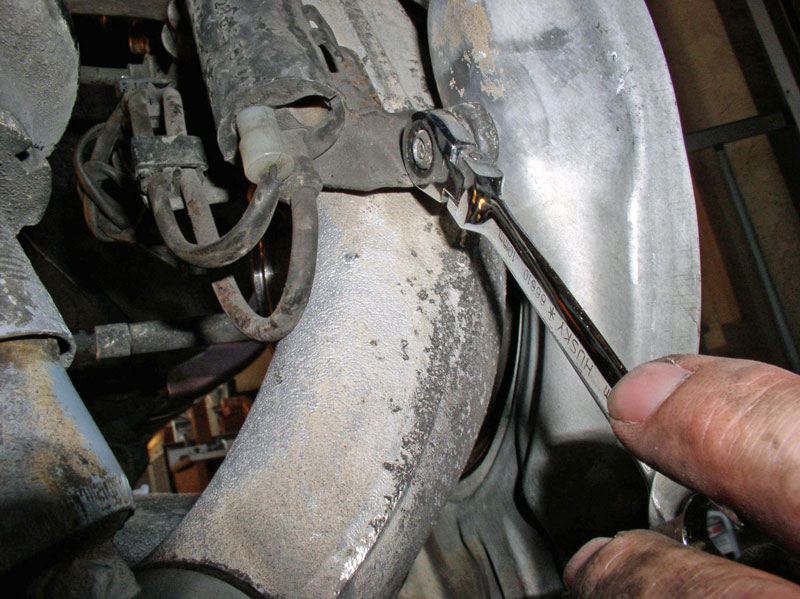
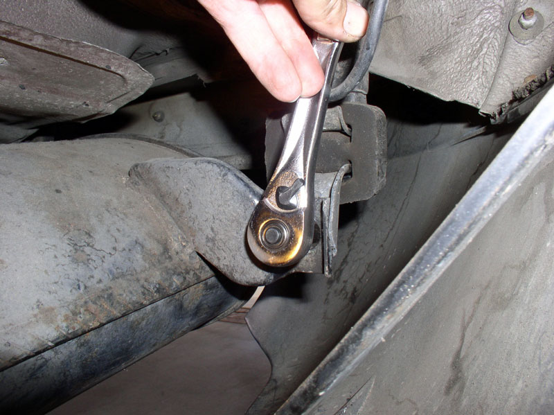
Torque the 19mm brake caliper bolts next to 85Nm or 60 ftlbs. Upper bolt pictured below.
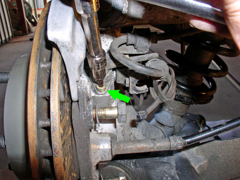
Lower bolt for brake caliper � 60 ftlbs. Repeat for the other wheel.
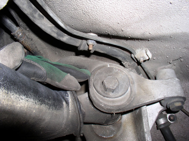
Line up the drop link to the lower control arm and install the 17mm bolt and torque to 46Nm or 33 ftlbs. If you have difficulty lining up the bolt due to the force on the drop link, you can disconnect the top of the drop link at the sway bar and then install the bolt enough to get it started. Then reconnect the upper drop link to the sway bar. Another method is to place a floor jack under the lower control arm and lift just enough to allow the drop link to line up with the lower control arm. It is best to use one of these methods if you are not getting the threads to line up as it will be likely you will cross thread the bolt. Repeat for the other wheel.
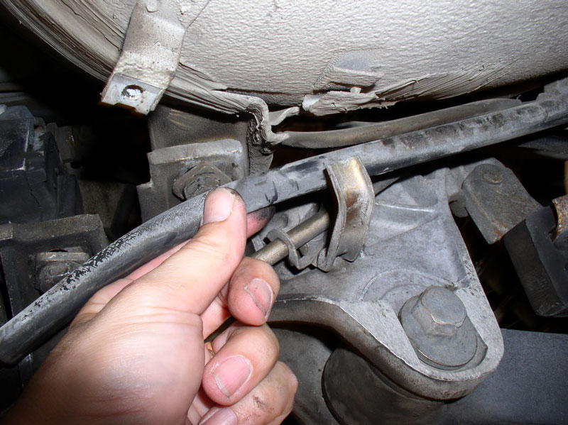
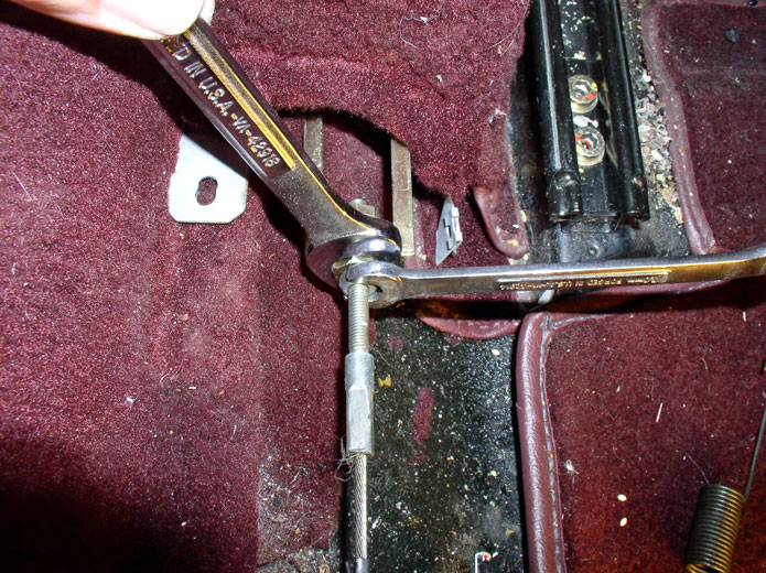
Next, we�ll install the axle half shafts. However, first the emergency brake must be connected so we can use it to hold the wheel in place while torquing the axle shaft to the differential. First, thread the 10mm nut onto the end of the emergency cable as shown below.
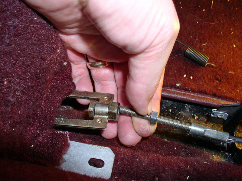
Next, thread the emergency brake cable into the adjusting nut on the emergency brake bracket as shown below. You will hold the cable while turning the adjusting nut to thread it.
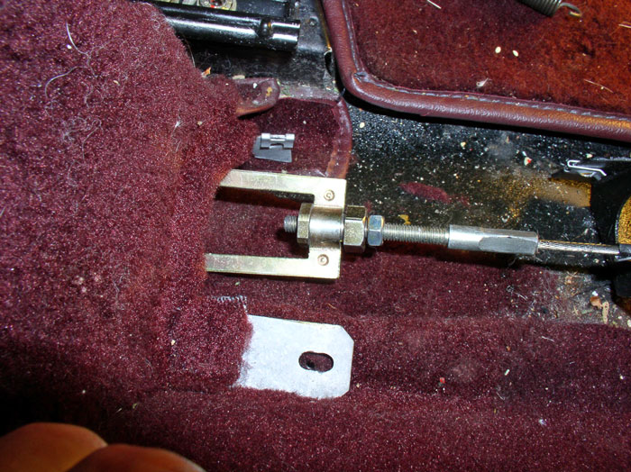
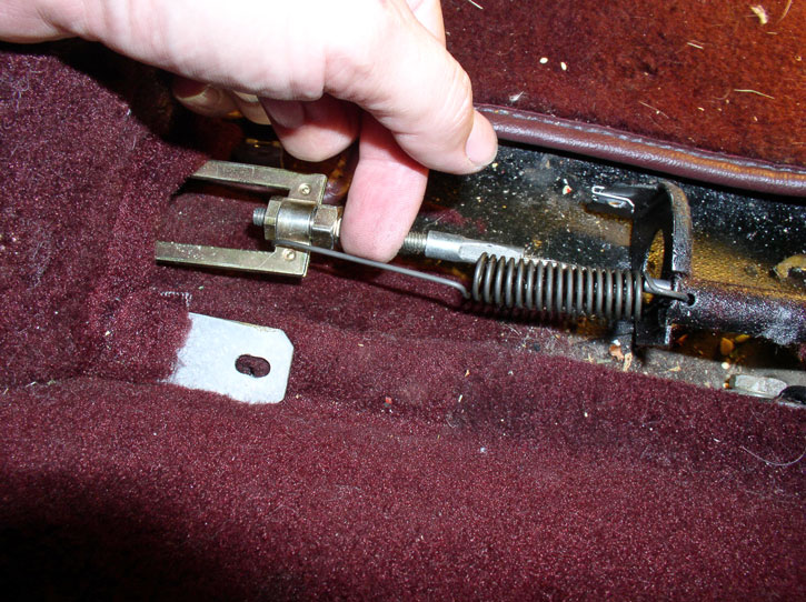
Test for emergency brake proper adjustment. I adjusted the cable tension so that I could feel and hear the emergency brakes begin to move when the first �click� on the handle was reached. Then, using a 10mm and 14mm wrench, I tightened the lock nut against the adjusting nut to lock them in place.
Attach the spring as shown below.
THIS STEP ONLY APPLIES IF YOU REMOVED THE AXLE SHAFTS TO REPAIR THE CV BOOTS. Line up the axle shaft with the wheel hub and insert the axle shaft. Press the axle shaft in until it is fully seated against the hub.
THIS STEP ONLY APPLIES IF YOU REMOVED THE AXLE SHAFTS TO REPAIR THE CV BOOTS. Install the washer on the end of the axle shaft.
THIS STEP ONLY APPLIES IF YOU REMOVED THE AXLE SHAFTS TO REPAIR THE CV BOOTS. Install the 32mm locknut on the end of the axle shaft to hold it in place.
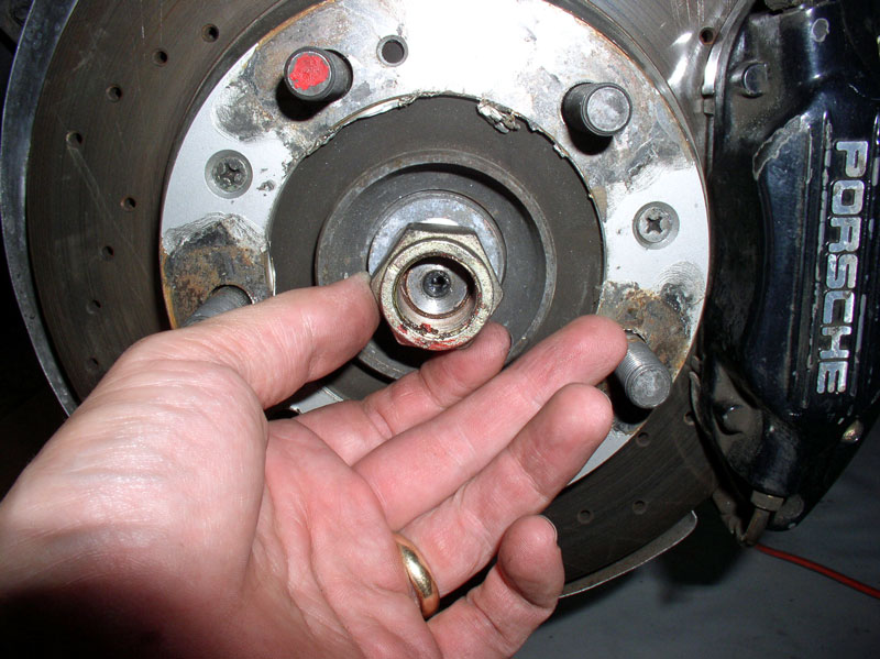
THIS STEP ONLY APPLIES IF YOU REMOVED THE AXLE SHAFTS TO REPAIR THE CV BOOTS. Set the emergency brake and use a 32mm socket to snug down the locknut. Do not torque to spec at this time � that will come later when the car is on the ground and weight on wheels. Repeat for the other wheel.
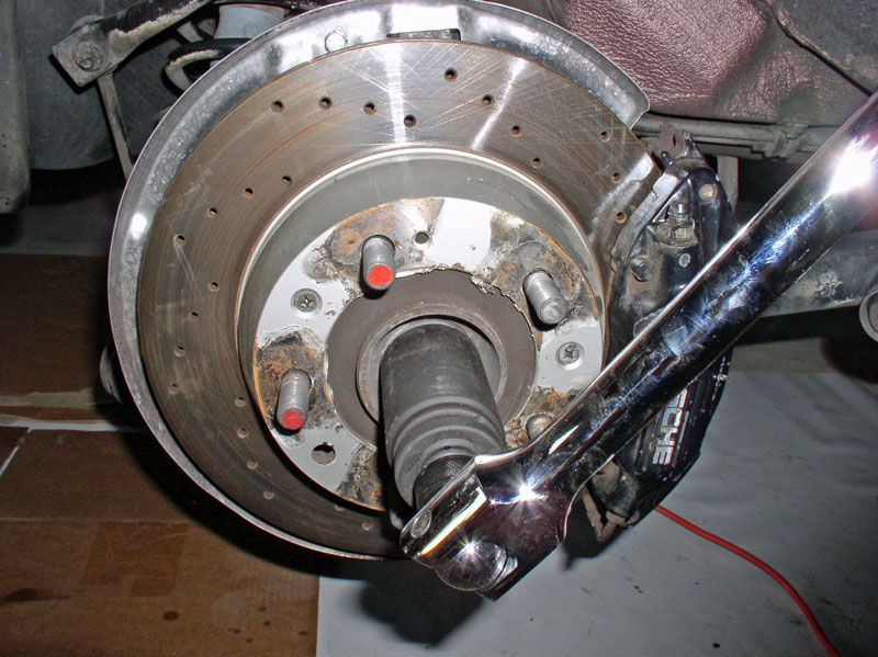
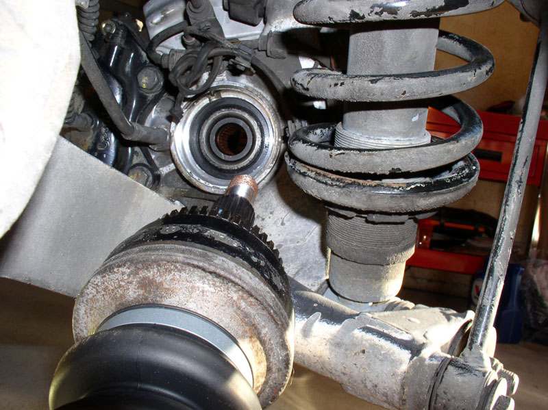
Ensure the emergency brake is released and align the inner CV joint with the mounting holes on the differential. I started the threads, by hand, on one of the Allen Head bolts so the CV joint would stay in place.
I then used the �T� handle ratchet wrench to quickly hand-tighten the 8mm Allen Head bolts. I rotated the wheels and tightened the bolts that were accessible until all 6 bolts were hand tightened. Repeat for the CV joint on the other side.
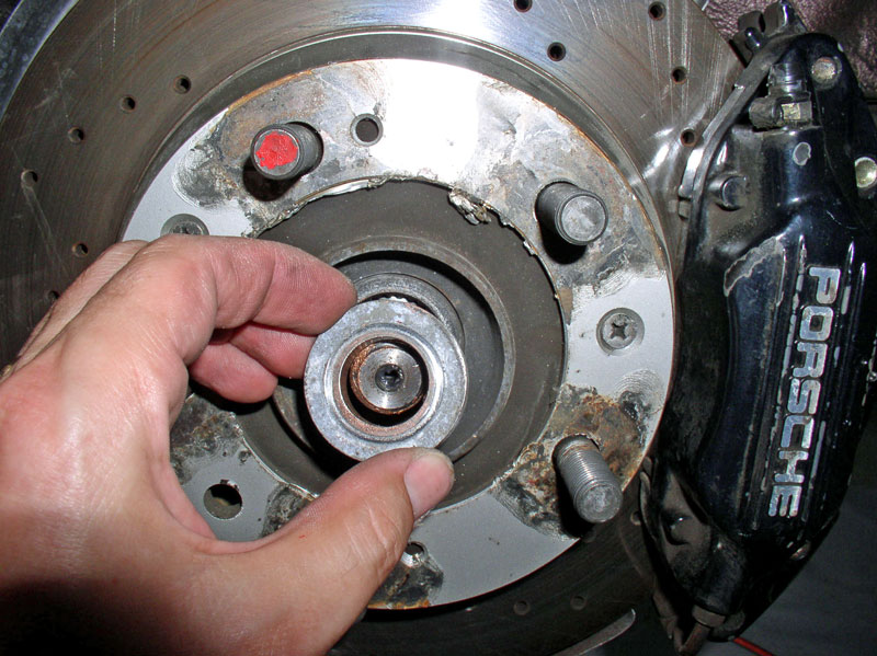
I then rotated the wheels so that 3 of the 8mm Allen Head bolts were accessible at a time as indicated by the green arrows in the picture below. I set the emergency brake and torqued the 3 exposed Allen Head bolts to 81Nm or 58 ftlbs. I moved to the other CV joint on the opposite side of the differential and torqued those 3 exposed bolts as well. Then release the emergency brake, rotate the wheels 180 degrees and re-set the emergency brake. The remaining 3 Allen Head bolts should be exposed. Torque the remaining bolts on both CV joints. When finished, you can release the emergency brake.
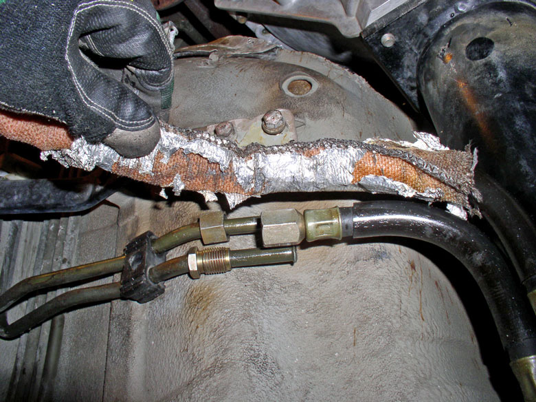
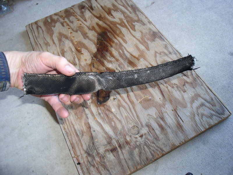
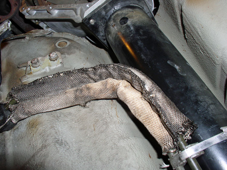
Next, I reconnected the transmission fluid cooler lines at the under body. After removing the plastic baggies, I noticed the fire retardant cloth was soaked with transmission fluid from the fluid that collected in the baggies. In addition, the thin foil covering on the outside was disintegrating. If the cloth has any transmission fluid on it, it should be cleaned and replaced so as not to risk starting a transmission fluid fire under the car. I removed the cloth from both intake and return hoses as shown.
Continued....
Lower bolt for brake caliper � 60 ftlbs. Repeat for the other wheel.
Line up the drop link to the lower control arm and install the 17mm bolt and torque to 46Nm or 33 ftlbs. If you have difficulty lining up the bolt due to the force on the drop link, you can disconnect the top of the drop link at the sway bar and then install the bolt enough to get it started. Then reconnect the upper drop link to the sway bar. Another method is to place a floor jack under the lower control arm and lift just enough to allow the drop link to line up with the lower control arm. It is best to use one of these methods if you are not getting the threads to line up as it will be likely you will cross thread the bolt. Repeat for the other wheel.
Next, we�ll install the axle half shafts. However, first the emergency brake must be connected so we can use it to hold the wheel in place while torquing the axle shaft to the differential. First, thread the 10mm nut onto the end of the emergency cable as shown below.
Next, thread the emergency brake cable into the adjusting nut on the emergency brake bracket as shown below. You will hold the cable while turning the adjusting nut to thread it.
Test for emergency brake proper adjustment. I adjusted the cable tension so that I could feel and hear the emergency brakes begin to move when the first �click� on the handle was reached. Then, using a 10mm and 14mm wrench, I tightened the lock nut against the adjusting nut to lock them in place.
Attach the spring as shown below.
THIS STEP ONLY APPLIES IF YOU REMOVED THE AXLE SHAFTS TO REPAIR THE CV BOOTS. Line up the axle shaft with the wheel hub and insert the axle shaft. Press the axle shaft in until it is fully seated against the hub.
THIS STEP ONLY APPLIES IF YOU REMOVED THE AXLE SHAFTS TO REPAIR THE CV BOOTS. Install the washer on the end of the axle shaft.
THIS STEP ONLY APPLIES IF YOU REMOVED THE AXLE SHAFTS TO REPAIR THE CV BOOTS. Install the 32mm locknut on the end of the axle shaft to hold it in place.
THIS STEP ONLY APPLIES IF YOU REMOVED THE AXLE SHAFTS TO REPAIR THE CV BOOTS. Set the emergency brake and use a 32mm socket to snug down the locknut. Do not torque to spec at this time � that will come later when the car is on the ground and weight on wheels. Repeat for the other wheel.
Ensure the emergency brake is released and align the inner CV joint with the mounting holes on the differential. I started the threads, by hand, on one of the Allen Head bolts so the CV joint would stay in place.
I then used the �T� handle ratchet wrench to quickly hand-tighten the 8mm Allen Head bolts. I rotated the wheels and tightened the bolts that were accessible until all 6 bolts were hand tightened. Repeat for the CV joint on the other side.
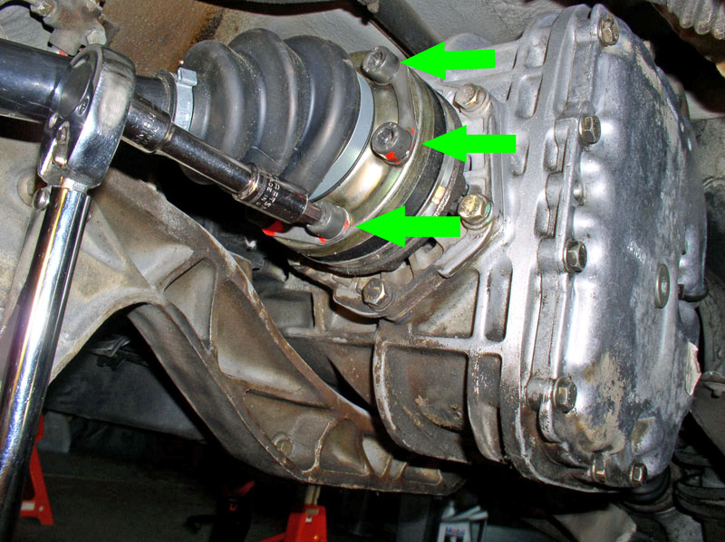
I then rotated the wheels so that 3 of the 8mm Allen Head bolts were accessible at a time as indicated by the green arrows in the picture below. I set the emergency brake and torqued the 3 exposed Allen Head bolts to 81Nm or 58 ftlbs. I moved to the other CV joint on the opposite side of the differential and torqued those 3 exposed bolts as well. Then release the emergency brake, rotate the wheels 180 degrees and re-set the emergency brake. The remaining 3 Allen Head bolts should be exposed. Torque the remaining bolts on both CV joints. When finished, you can release the emergency brake.
Next, I reconnected the transmission fluid cooler lines at the under body. After removing the plastic baggies, I noticed the fire retardant cloth was soaked with transmission fluid from the fluid that collected in the baggies. In addition, the thin foil covering on the outside was disintegrating. If the cloth has any transmission fluid on it, it should be cleaned and replaced so as not to risk starting a transmission fluid fire under the car. I removed the cloth from both intake and return hoses as shown.
Continued....
12-20-2010, 11:22 AM
#58
Three Wheelin'
Thread Starter
Join Date: Sep 2007
Location: Ridgecrest, California
Posts: 1,363
Likes: 0
Received 148 Likes
on
32 Posts
I thought the best way to clean off the transmission oil was to simply burn it off. I found this experiment very educational as it demonstrated how flammable transmission fluid can be. I placed the cloth on a scrap piece of plywood and lit it with a lighter.
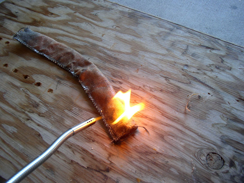
The transmission fluid burns easily and yet the fire-proof cloth does not.
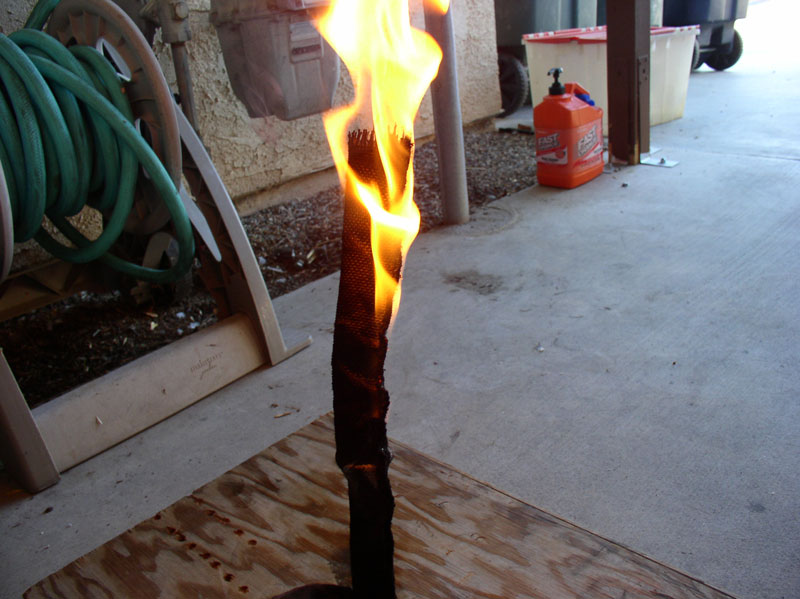
When the flames go out, there wasn�t a trace of fluid left.
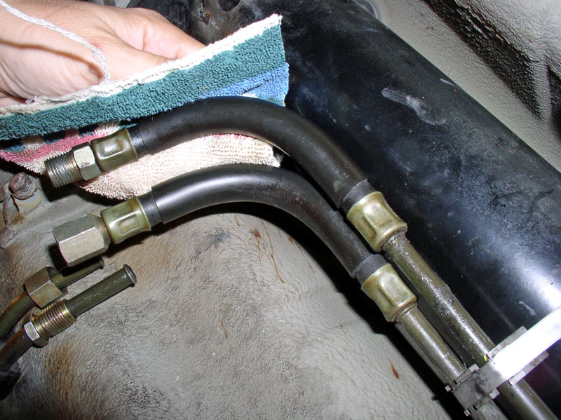
Next, I wiped down the rubber hoses to remove any traces of fluid there as well. Of course, if you replaced these lines with new ones or replaced the rubber parts of the lines with new hose, this step would not be needed.
Place the fire retardant cloths over both rubber hose sections as shown below.
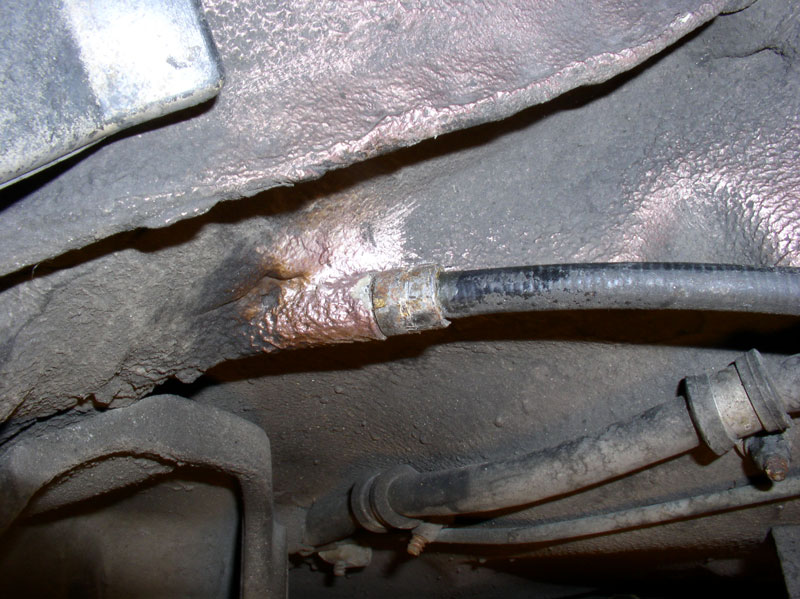
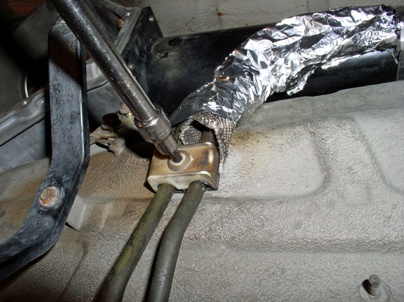
Using 17mm and 19mm wrenches, tighten the rubber hose to hard line connections. The nuts and mating threads are opposite on each hose so it�s impossible to mix them up.
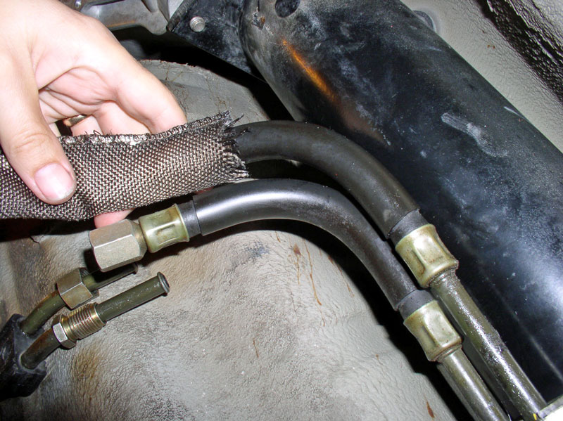
After tightening, pull the protective fire retardant cloth over the hose and connections as shown in the picture below.
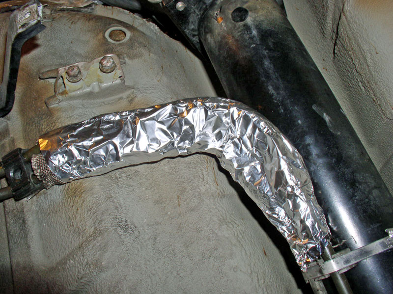
Since the original foil wrapping on the cloth was destroyed, I improvised and wrapped the hoses with aluminum foil as shown below.
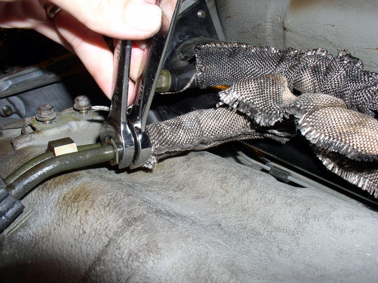
Lastly, tighten the plastic hard line clamp. The Allen Head screw is plastic and takes a 5mm Allen Head socket. Do not over tighten.
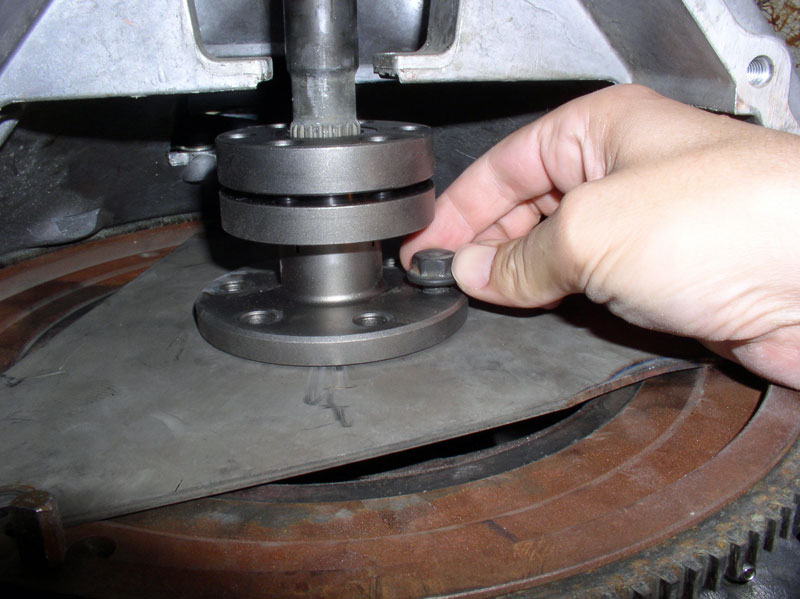
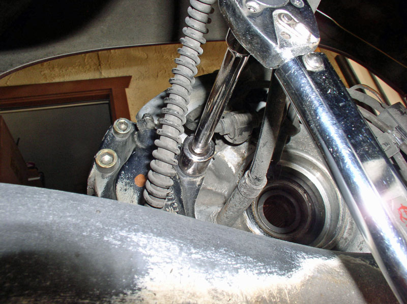
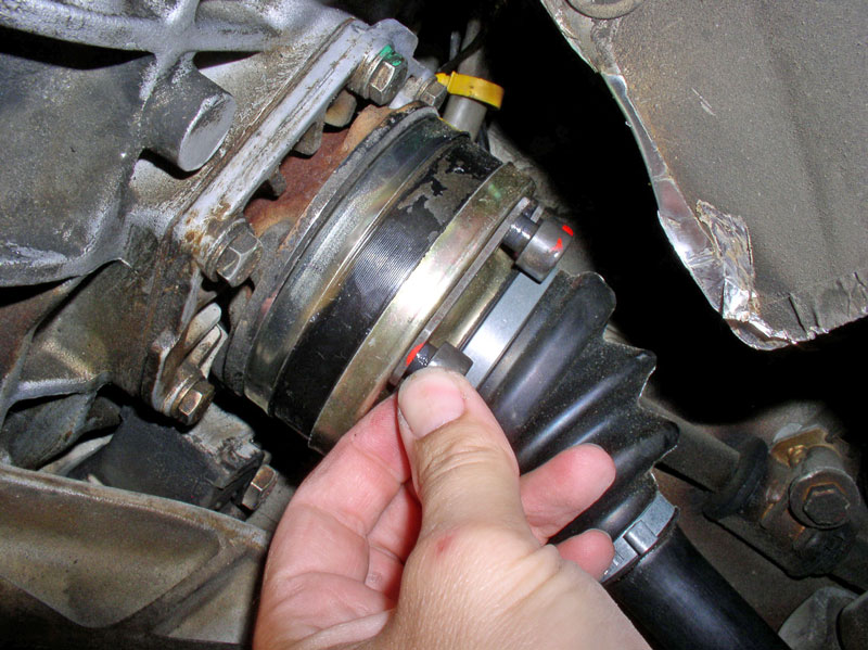
I then worked on tightening the Super Clamp down on the drive shaft. First, I pried the flywheel rearward to position the crank shaft off the rearward face of the thrust bearing.
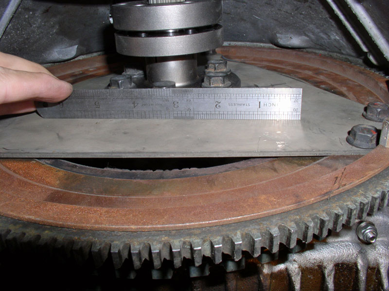
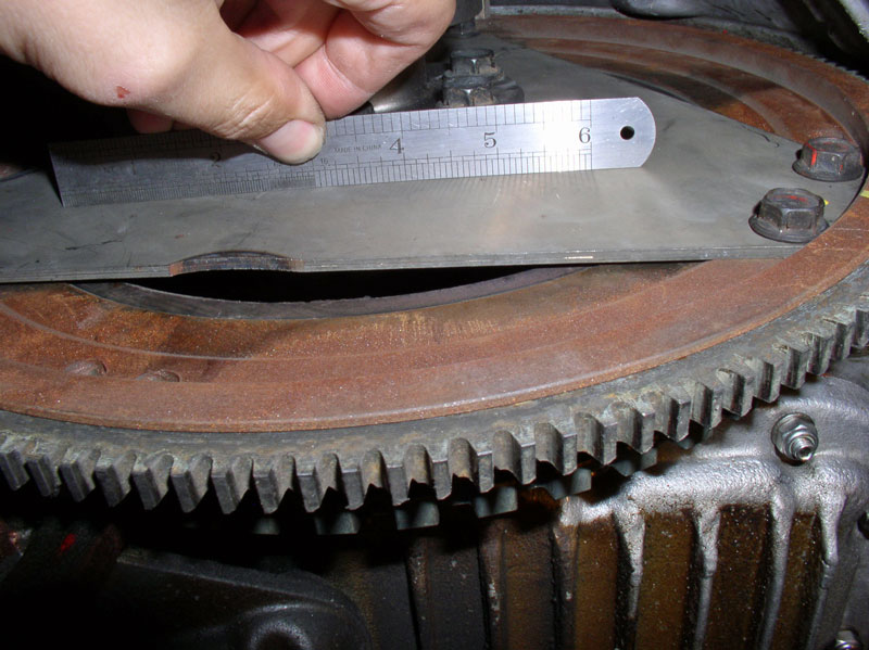
I checked the flex plate with a straight edge to ensure there was no pre-loading. There should be no gaps between the edge of the straight edge and the surface of the flex plate.
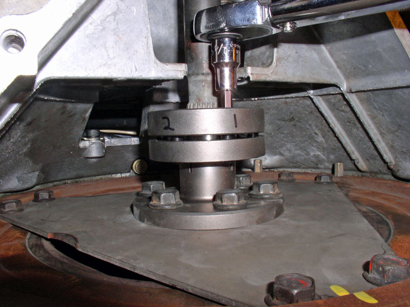
I used a sharpie permanent marker to mark each of the 6 Allen Head bolts on the Super Clamp as shown below. This made it easier to keep track of which bolts I had already tightened during the tightening sequence. I used a � inch Allen Head socket for tightening. On the first round, I simply snugged down all the Allen Head bolts by hand before applying the torque wrench to make sure the Super Clamp was tightening down in a uniform manner to start with. You will observe the gap between the two halves of the Super Clamp as you are tightening and ensure the gap is consistent from side to side as shown in the picture below. I then began the torquing sequence. Starting with bolt #1, torque to 25 ftlbs.
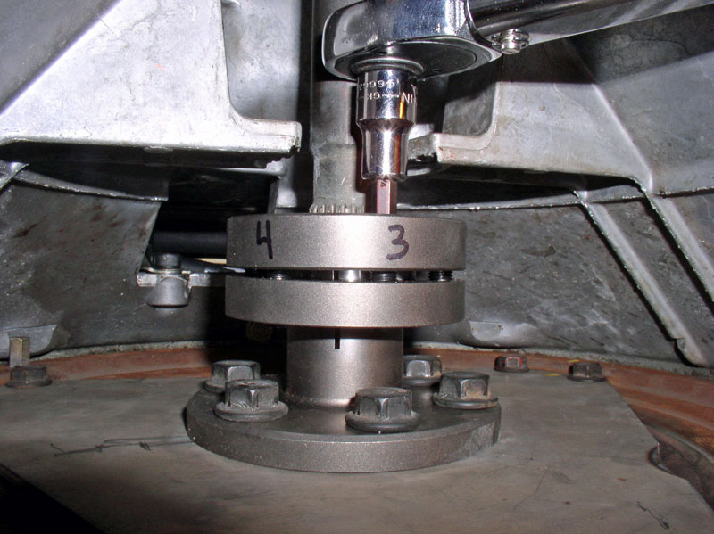
Rotate the flywheel (engine) clockwise (as you are standing in front of the car) and torque bolt #3 to 25 ftlbs.
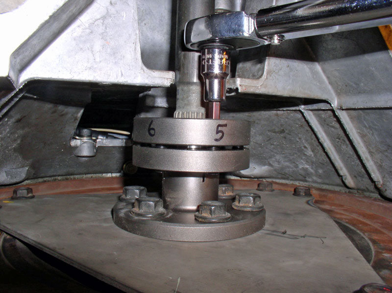
Rotate the engine/flywheel again and torque bolt #5 to 25 ftlbs. I then worked the even numbered bolts in the same manner as the odd bolts starting with bolt #2, then #4, then #6 torquing each to 25 ftlbs. I then went back to the odd numbered bolts 1, 3, and 5 torquing each to 25 ftlbs. You will notice as you cycle again back to the bolts previously torqued, that they will continue to tighten (i.e., they won�t be torqued to 25 ftlbs on subsequent passes). Constantine explains in his Super Clamp instructions that is perfectly natural and is an artifact of the Super Clamp�s design. Therefore, continue the torquing sequence. I continued in this manner (re-torquing the bolts alternating between odd and even bolts) until all the bolts were fully torqued to 25 ftlbs with no movement.
After all the Super Clamp bolts were torqued, I checked the flex plate against a straight edge once more to ensure there were no gaps and therefore, no pre-loading on the thrust bearing.
Continued....
The transmission fluid burns easily and yet the fire-proof cloth does not.
When the flames go out, there wasn�t a trace of fluid left.
Next, I wiped down the rubber hoses to remove any traces of fluid there as well. Of course, if you replaced these lines with new ones or replaced the rubber parts of the lines with new hose, this step would not be needed.
Place the fire retardant cloths over both rubber hose sections as shown below.
Using 17mm and 19mm wrenches, tighten the rubber hose to hard line connections. The nuts and mating threads are opposite on each hose so it�s impossible to mix them up.
After tightening, pull the protective fire retardant cloth over the hose and connections as shown in the picture below.
Since the original foil wrapping on the cloth was destroyed, I improvised and wrapped the hoses with aluminum foil as shown below.
Lastly, tighten the plastic hard line clamp. The Allen Head screw is plastic and takes a 5mm Allen Head socket. Do not over tighten.
I then worked on tightening the Super Clamp down on the drive shaft. First, I pried the flywheel rearward to position the crank shaft off the rearward face of the thrust bearing.
I checked the flex plate with a straight edge to ensure there was no pre-loading. There should be no gaps between the edge of the straight edge and the surface of the flex plate.
I used a sharpie permanent marker to mark each of the 6 Allen Head bolts on the Super Clamp as shown below. This made it easier to keep track of which bolts I had already tightened during the tightening sequence. I used a � inch Allen Head socket for tightening. On the first round, I simply snugged down all the Allen Head bolts by hand before applying the torque wrench to make sure the Super Clamp was tightening down in a uniform manner to start with. You will observe the gap between the two halves of the Super Clamp as you are tightening and ensure the gap is consistent from side to side as shown in the picture below. I then began the torquing sequence. Starting with bolt #1, torque to 25 ftlbs.
Rotate the flywheel (engine) clockwise (as you are standing in front of the car) and torque bolt #3 to 25 ftlbs.
Rotate the engine/flywheel again and torque bolt #5 to 25 ftlbs. I then worked the even numbered bolts in the same manner as the odd bolts starting with bolt #2, then #4, then #6 torquing each to 25 ftlbs. I then went back to the odd numbered bolts 1, 3, and 5 torquing each to 25 ftlbs. You will notice as you cycle again back to the bolts previously torqued, that they will continue to tighten (i.e., they won�t be torqued to 25 ftlbs on subsequent passes). Constantine explains in his Super Clamp instructions that is perfectly natural and is an artifact of the Super Clamp�s design. Therefore, continue the torquing sequence. I continued in this manner (re-torquing the bolts alternating between odd and even bolts) until all the bolts were fully torqued to 25 ftlbs with no movement.
After all the Super Clamp bolts were torqued, I checked the flex plate against a straight edge once more to ensure there were no gaps and therefore, no pre-loading on the thrust bearing.
Continued....
12-20-2010, 11:27 AM
#59
Three Wheelin'
Thread Starter
Join Date: Sep 2007
Location: Ridgecrest, California
Posts: 1,363
Likes: 0
Received 148 Likes
on
32 Posts
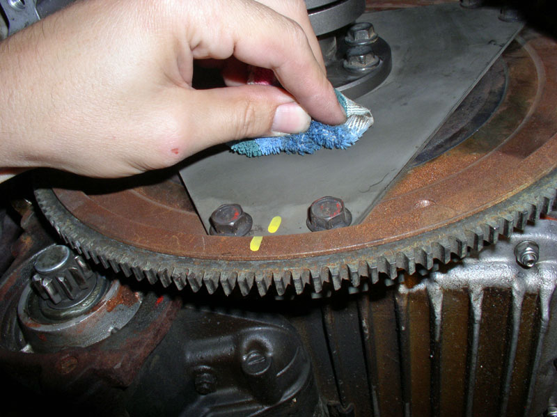
Lastly, clean a spot off the flex plate�..
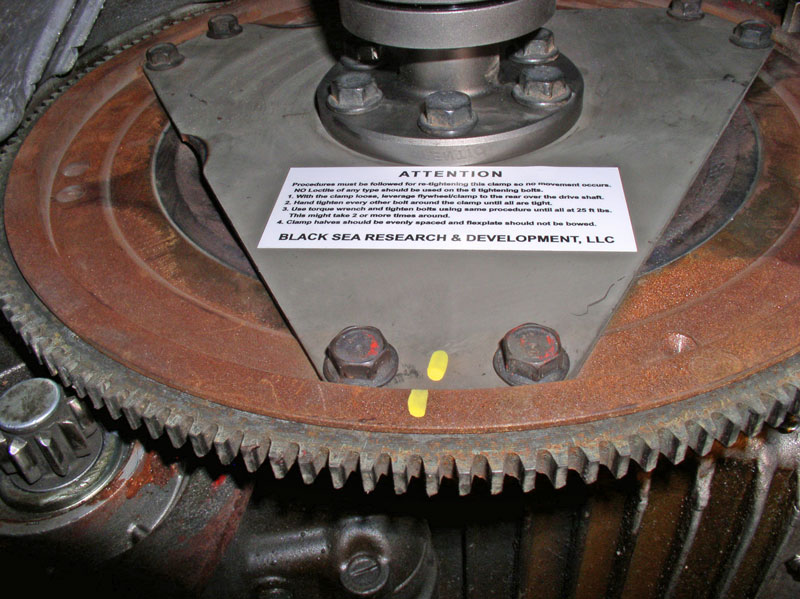
�.and apply Constantine�s Super Clamp Tightening instructions to the flex plate as shown below.
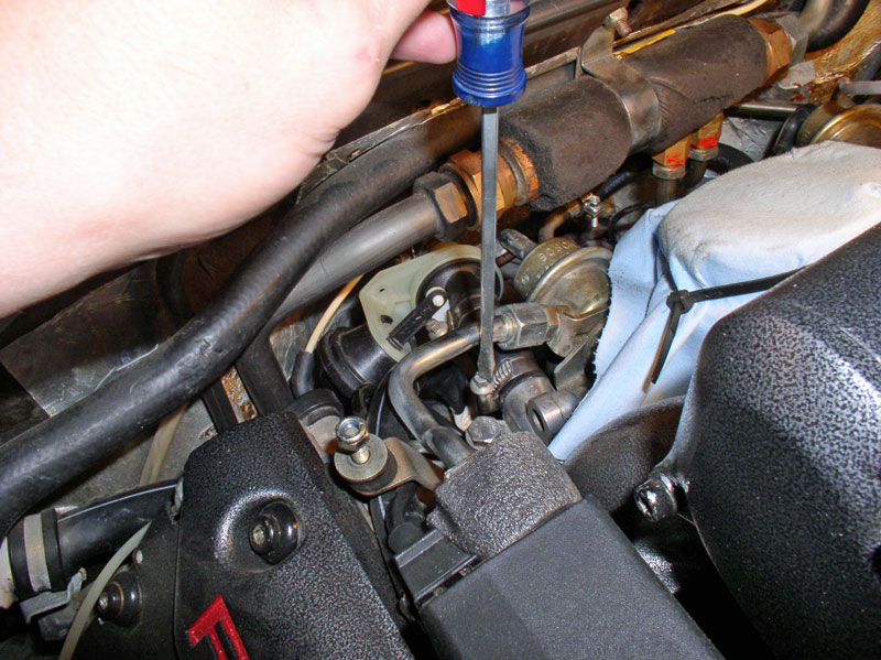
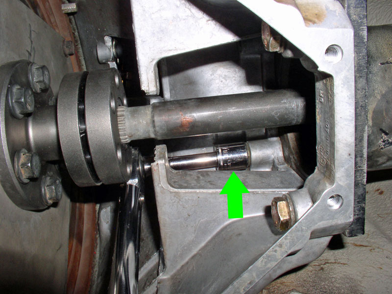
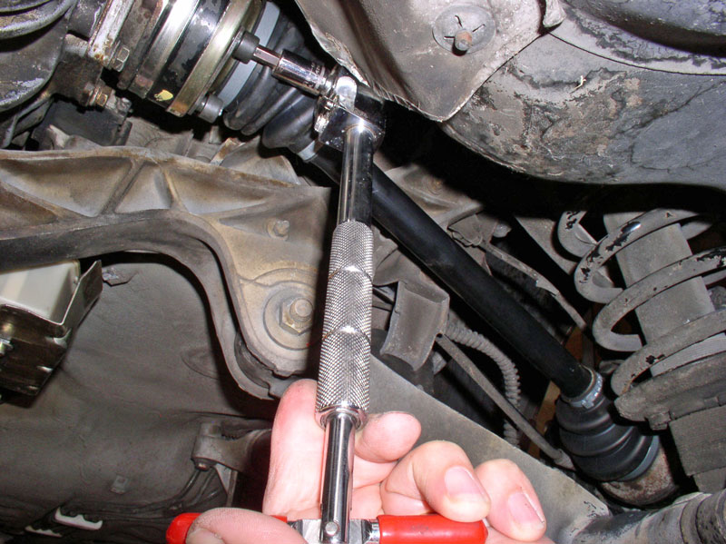
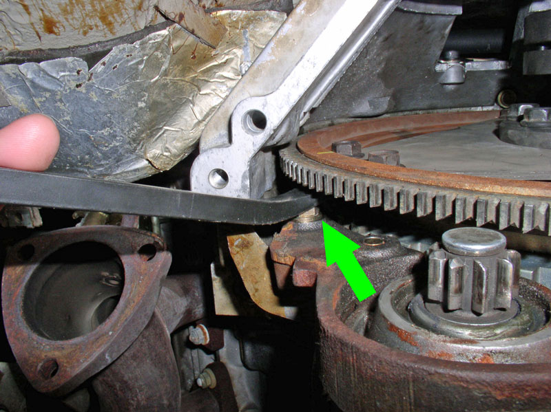
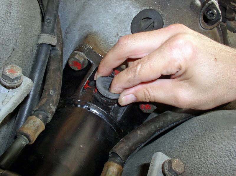
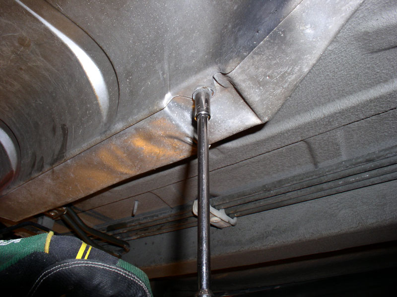
Moving to the rear of the TT, the rear drive shaft clamp pinch bolt needs to be torqued to spec. Rotate the engine clockwise until the Allen Head bolt is accessible through the port as shown in the picture below.
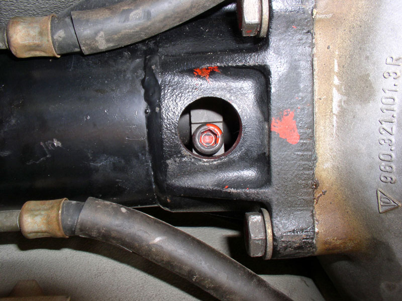
Using an 8mm Allen Head socket, torque the pinch bolt to 80Nm or 60 ftlbs.
Install the rubber inspection port cover as shown.
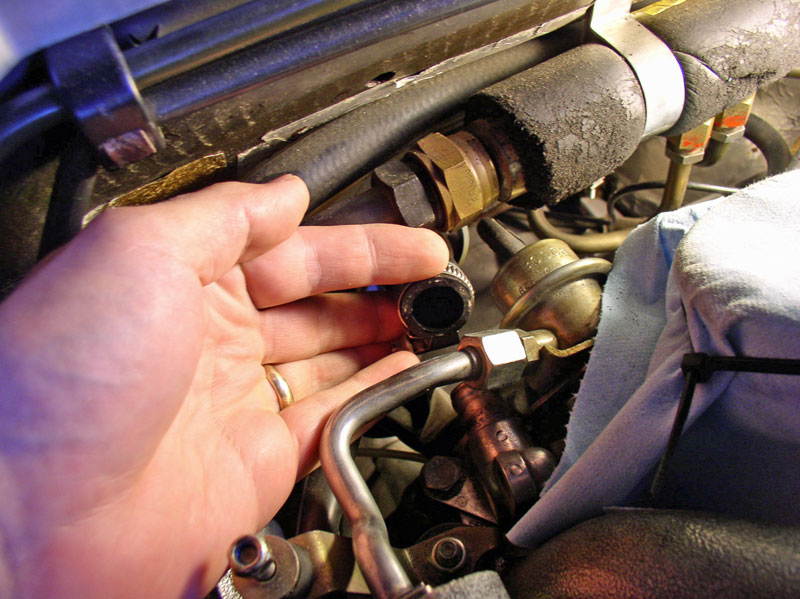
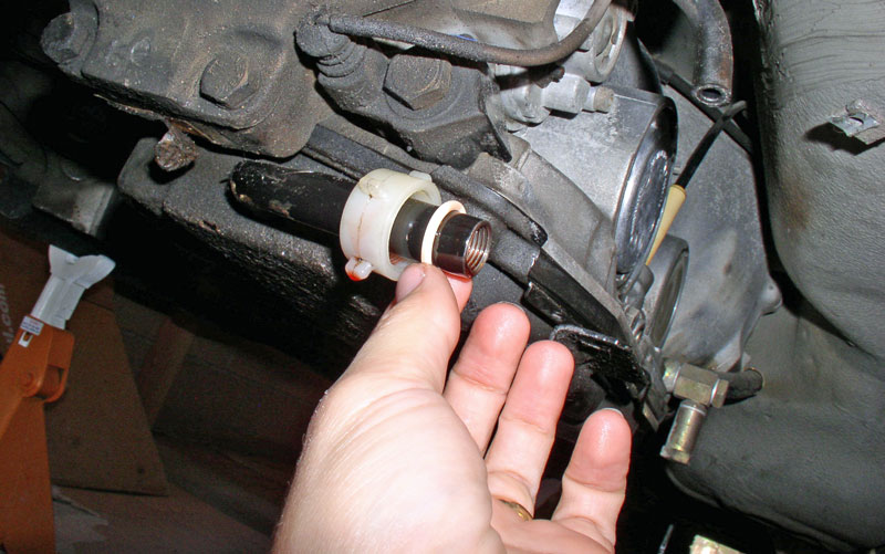
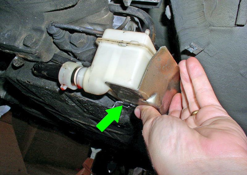
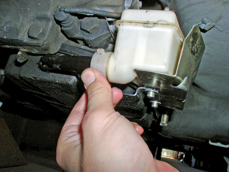
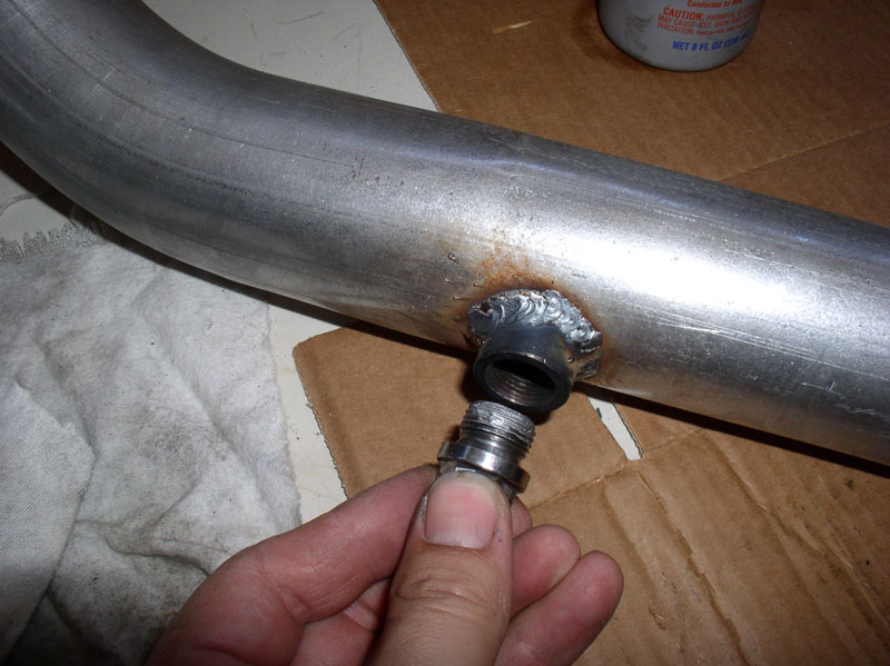
One last item to install before moving on to the exhaust system � the transmission fluid reservoir. Remove the stopper on the end of the filler tube and install the plastic nut and new O-Ring as shown below.
Slide the reservoir drain hole over the filler tube while at the same time positioning the reservoir on top of the fluid pan flange as shown in the picture below. Align the mounting holes in the pan tab with the threads in the bottom of the reservoir as indicated by the green arrow below.
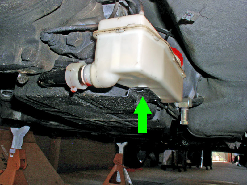
Insert the reservoir protective shield between the fluid pan tab and the bottom of the plastic reservoir as shown below.
Install the two 5mm Allen Head bolts that secure the reservoir to the fluid pan tab as shown. I simply snugged the bolts down � don�t over tighten.
Next, hand tighten the filler tube plastic nut so it�s snugged securely on the reservoir. There should be no need to tighten with a tool such as pliers. You do not want to deform the O-Ring or strip the plastic threads.
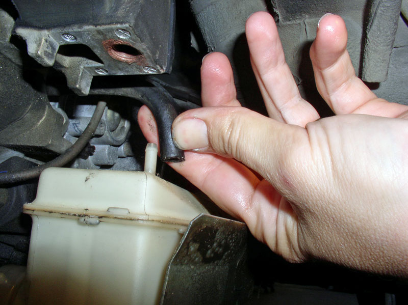
Lastly, re-connect the rubber hose to the top of the reservoir as shown below.
Next comes the exhaust system installation.
�.and apply Constantine�s Super Clamp Tightening instructions to the flex plate as shown below.
Moving to the rear of the TT, the rear drive shaft clamp pinch bolt needs to be torqued to spec. Rotate the engine clockwise until the Allen Head bolt is accessible through the port as shown in the picture below.
Using an 8mm Allen Head socket, torque the pinch bolt to 80Nm or 60 ftlbs.
Install the rubber inspection port cover as shown.
One last item to install before moving on to the exhaust system � the transmission fluid reservoir. Remove the stopper on the end of the filler tube and install the plastic nut and new O-Ring as shown below.
Slide the reservoir drain hole over the filler tube while at the same time positioning the reservoir on top of the fluid pan flange as shown in the picture below. Align the mounting holes in the pan tab with the threads in the bottom of the reservoir as indicated by the green arrow below.
Insert the reservoir protective shield between the fluid pan tab and the bottom of the plastic reservoir as shown below.
Install the two 5mm Allen Head bolts that secure the reservoir to the fluid pan tab as shown. I simply snugged the bolts down � don�t over tighten.
Next, hand tighten the filler tube plastic nut so it�s snugged securely on the reservoir. There should be no need to tighten with a tool such as pliers. You do not want to deform the O-Ring or strip the plastic threads.
Lastly, re-connect the rubber hose to the top of the reservoir as shown below.
Next comes the exhaust system installation.
12-20-2010, 11:46 AM
#60
Three Wheelin'
Thread Starter
Join Date: Sep 2007
Location: Ridgecrest, California
Posts: 1,363
Likes: 0
Received 148 Likes
on
32 Posts
CH16 INSTALLING EXHAUST SYSTEM
In this chapter, the heat shield braces, heat shields, rear exhaust, and X-Pipe with Cats are installed. Re-Installing the exhaust system will require installation of the heat shields first. There are two braces that help support the heat shields. Install the forward brace by securing it to the under body with four 13mm bolts. Orient the brace as shown below.
Install the rear brace next with four 13mm bolts. Orient the brace so the three speed clips for the heat shield mounting screws are toward the rear of the car as shown below.
I installed the driver�s side forward heat shield first. Secure the heat shield with the two 8mm sheet metal screws as indicated by the green arrows. I waited to install the right (passenger side) forward heat shield until after I installed the exhaust system due to routing the O2 sensor harness behind the heat shield.
I installed the center heat shield that runs along most of the TT next. Secure the rear two 8mm screws as shown below.
Install the remaining screws to secure the center heat shield.
Next, install the driver�s side rear resonator heat shield. Install the remaining 8mm screws that secure the heat shield.
Install the right (passenger side) resonator heat shield next. The right resonator heat shield will be placed on top of the left (driver�s side) heat shield when installed as shown below. Install the remaining 8mm screws that secure the right heat shield.
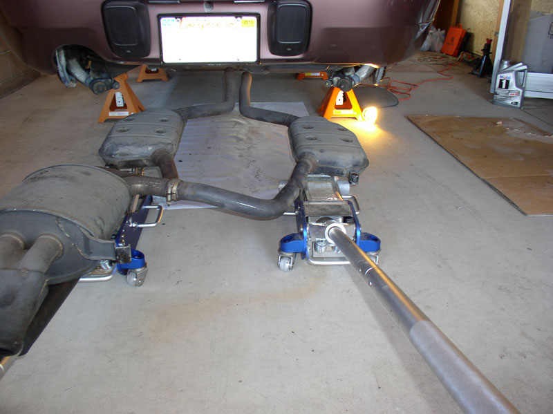
I then placed the resonators on two floor jacks as shown below and aligned the system with the heat shields just installed and rolled it into place under the car.
I began raising the floor jacks to position the exhaust system near the support hangars. When raising the system, you will need to guide the rear muffler hangar support tab up and around the rear bumper cover as indicated by the green arrows below.
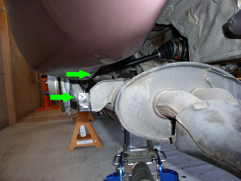
I started securing the exhaust system to the support hangars by first attaching the rear hangar just behind the battery box as shown below. I started the lock nut on the bolt but did not tighten. The hangars do allow height adjustment of the exhaust system since the mounting holes in the brackets are elongated. I wanted to install all the hangars loosely so I could adjust the height of the exhaust system before locking all the hangars in place. All the exhaust hangar bolts and nuts are 13mm.
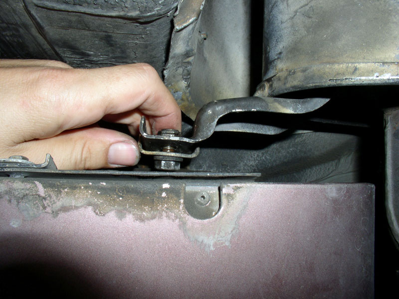
I installed the hangar bolts and nuts at the resonator support brackets next � both sides.
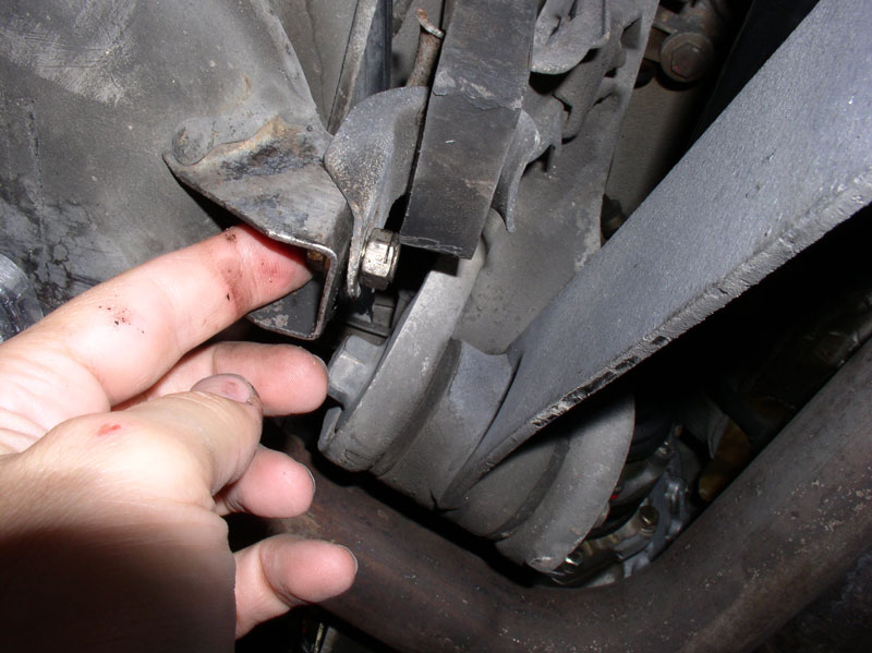
If you haven�t done so already, remove the rear splash shield exposing the side muffler hangar support bracket.
Install the rear muffler side support bracket bolt and nut as shown.
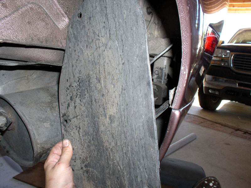
At this point, I raised the floor jacks so the support brackets were at the desired height (for me, all the way up) and I tightened all the hangar bolts and nuts using a 13mm socket and a 13mm closed end wrench to counter hold. I removed the floor jacks when done. Re-install the rear left (driver�s side) wheel well splash guard.
At this point, the forward section of the exhaust system with catalytic converter is installed next. If you are re-installing the factory exhaust with cats, you can install in the same order it was removed (see chapter 2). We purchased an X-Pipe system with Cats from Roger Tyson and that system is depicted in the next several pictures. First, I installed the exhaust plug on the left (driver�s side) of the X-Pipe. I applied some silver anti-seize to the threads. I also replaced the O2 sensor. If you also replaced the O2 sensor, you may consider installing the connection at the Central Electric Board now by feeding the harness connector through the access hole in the floor board and pressing the grommet into place so it is fully seated before installing the X-Pipe due to the reduced clearances after the X-Pipe is installed.
Continued....
In this chapter, the heat shield braces, heat shields, rear exhaust, and X-Pipe with Cats are installed. Re-Installing the exhaust system will require installation of the heat shields first. There are two braces that help support the heat shields. Install the forward brace by securing it to the under body with four 13mm bolts. Orient the brace as shown below.
Install the rear brace next with four 13mm bolts. Orient the brace so the three speed clips for the heat shield mounting screws are toward the rear of the car as shown below.
I installed the driver�s side forward heat shield first. Secure the heat shield with the two 8mm sheet metal screws as indicated by the green arrows. I waited to install the right (passenger side) forward heat shield until after I installed the exhaust system due to routing the O2 sensor harness behind the heat shield.
I installed the center heat shield that runs along most of the TT next. Secure the rear two 8mm screws as shown below.
Install the remaining screws to secure the center heat shield.
Next, install the driver�s side rear resonator heat shield. Install the remaining 8mm screws that secure the heat shield.
Install the right (passenger side) resonator heat shield next. The right resonator heat shield will be placed on top of the left (driver�s side) heat shield when installed as shown below. Install the remaining 8mm screws that secure the right heat shield.
I then placed the resonators on two floor jacks as shown below and aligned the system with the heat shields just installed and rolled it into place under the car.
I began raising the floor jacks to position the exhaust system near the support hangars. When raising the system, you will need to guide the rear muffler hangar support tab up and around the rear bumper cover as indicated by the green arrows below.
I started securing the exhaust system to the support hangars by first attaching the rear hangar just behind the battery box as shown below. I started the lock nut on the bolt but did not tighten. The hangars do allow height adjustment of the exhaust system since the mounting holes in the brackets are elongated. I wanted to install all the hangars loosely so I could adjust the height of the exhaust system before locking all the hangars in place. All the exhaust hangar bolts and nuts are 13mm.
I installed the hangar bolts and nuts at the resonator support brackets next � both sides.
If you haven�t done so already, remove the rear splash shield exposing the side muffler hangar support bracket.
Install the rear muffler side support bracket bolt and nut as shown.
At this point, I raised the floor jacks so the support brackets were at the desired height (for me, all the way up) and I tightened all the hangar bolts and nuts using a 13mm socket and a 13mm closed end wrench to counter hold. I removed the floor jacks when done. Re-install the rear left (driver�s side) wheel well splash guard.
At this point, the forward section of the exhaust system with catalytic converter is installed next. If you are re-installing the factory exhaust with cats, you can install in the same order it was removed (see chapter 2). We purchased an X-Pipe system with Cats from Roger Tyson and that system is depicted in the next several pictures. First, I installed the exhaust plug on the left (driver�s side) of the X-Pipe. I applied some silver anti-seize to the threads. I also replaced the O2 sensor. If you also replaced the O2 sensor, you may consider installing the connection at the Central Electric Board now by feeding the harness connector through the access hole in the floor board and pressing the grommet into place so it is fully seated before installing the X-Pipe due to the reduced clearances after the X-Pipe is installed.
Continued....