


Tachometer calibration
Thread Starter
Nordschleife Master
Joined: Jan 2009
Posts: 5,609
Likes: 84
From: MA
I bought a tachometer off fleabay. It's a 951 unit.

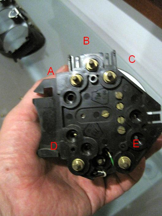
Here's a photo of the pin connectors:
So I took a digital signal/wave generator and tested the tacho. Here's what I found for this particular tacho:
My photo pin A connected to ground
My photo pin B connected to a square-wave source
My photo pin C connected to 12v
In the car, the tacho signal is coming from the ignition. Therefore, the correct reading for the tacho should be the 30/Hz of the input signal. I used 5v amplitude, 2.5v offset, 50% pulse width, and square wave. This is something not too different from what the EZK should give, right?
Here are my empirical measurements:
Hz multiplier true RPM gauge RPM
21.2 0.5 636 750
33.3 0.5 998 1100
41.1 0.5 1234 1350
69.5 0.5 2086 2100
84.8 0.5 2544 2575
117.2 0.5 3516 3425
122.3 0.5 3670 3500
169.6 0.5 5088 4800
222.6 0.5 6677 5450
244.7 0.5 7341 6000
245.9 0.5 7378 6000
In other words, very inaccurate after true 5000 rpm. After about 7400 true rpm, the gauge tilts and starts reading about 4000 rpm. Can't get it to read to the official red line. In other words, a driver relying on this tacho would never think he's overreving the engine, no matter what the rpm.
There are two trim pots in the tacho. Neither made much difference in the calibration range.
If this is a representative tacho, couldn't you read the 951 rpm from tea leaves near the redline with an accuracy comparable to that of the factory tacho? Or did I just buy an unusually defective unit from fleabay? Or did I test it wrong?
The 928 tacho appears to be very similar, so I wouldn't be shocked if many of our tachos as off by a lot, too.
Under the Lift
Lifetime Rennlist
Member
Lifetime Rennlist
Member

Joined: Mar 2002
Posts: 18,648
Likes: 52
From: Buckeye, AZ
Puzzling. You say the 928 tach has similar errors. I think we'd recognize the difference between 6000 indicated and 7400 actual. Wow! John Speake or Theo J should be able to shed some light on this as they programmed their software to capture and display RPM. Also, I've used the data logging function included in two NB O2 sensor packages to display and record RPM from the tach signal on pin 14 on the diagnostic plug and haven't found them to disagree widely with the gauge.

Chronic Tool Dropper
Lifetime Rennlist
Member
Lifetime Rennlist
Member
Joined: Oct 2001
Posts: 20,506
Likes: 565
From: Bend, Oregon
Perhaps you discovered the reason it was on E-bay.
Also--
Does the EZK send 5V squares? Might be worth sticking a 'scope on the factory tach signal (it's easy to get to at a couple CE panel connectors for test purposes) and see what's normally delivered. Considering that it's coming across on unshielded wiring, it may be a little higher peak voltage. I'd check that before condemning the part you found.
Gotta ask-- what's the need for the 951 tach? Curious...
Thread Starter
Nordschleife Master
Joined: Jan 2009
Posts: 5,609
Likes: 84
From: MA
I didn't say that all 928 gauges have similar errors. Just that this 951 gauge appears to be off at higher rpm and that 928 gauges appear to be otherwise similar to 951 gauges (only the boost gauge part is different), therefore some 928 may be similarly off. Or maybe not. Sample is one, tomorrow it'll probably be two, so this experimental result is not yet statistically significant! ;-)
My test procedure may also be off, I may have simply made some sort of error either with the formula or my test instruments. In fact this is the most likely explanation, and I just posted the procedure and results here to see if someone caught an obvious error in what I did.
Your point about people logging digital data being able to check their tachos is excellent. With this tacho, the error only started showing well after 5000 rpm, and I don't know if people doing over 5000 rpm on the road in their 928s will by default be simultaneously looking at the analog gauge and the data logger display. But if one just wants to do a quick check, it'll be easy to do if one has any digital rpm display driven off from say the ignition. All dynos have the display, too, so the dyno operator could easily check this.
Puzzling. You say the 928 tach has similar errors. I think we'd recognize the difference between 6000 indicated and 7400 actual. Wow! John Speake or Theo J should be able to shed some light on this as they programmed their software to capture and display RPM. Also, I've used thedata logging function included in two NB O2 sensor packages to display and record RPM from the tach signal on pin 14 on the diagnostic plug and haven't found them to disagree widely with the gauge.
Thread Starter
Nordschleife Master
Joined: Jan 2009
Posts: 5,609
Likes: 84
From: MA
Exactly the right first reaction, except this one has 30 days to return it if it doesn't work. The seller probably wouldn't have promised that if he knew it's busted.
I got those off from 944 list. But since I am curious & the financial risk is low, I tried increasing the amplitude to 6v and offset to 3v. Made no difference to results at any rpm. I also tried varying the pulse width in the range 25%-75%, again no difference at any rpm. Since it gives about stable results up to 5,000 rpm, the signal is probably ok.
I want to do what PorKen did, put a boost gauge in the 928 instrument cluster! Imitation is the sincerest form of flattery.
I also was planning to play with some of the adjustments in the tacho to see if one could get it to "go to 11" just by home-grown recalibration and printed face sticker.
Does the EZK send 5V squares? Might be worth sticking a 'scope on the factory tach signal (it's easy to get to at a couple CE panel connectors for test purposes) and see what's normally delivered. Considering that it's coming across on unshielded wiring, it may be a little higher peak voltage. I'd check that before condemning the part you found.
I want to do what PorKen did, put a boost gauge in the 928 instrument cluster! Imitation is the sincerest form of flattery.
I also was planning to play with some of the adjustments in the tacho to see if one could get it to "go to 11" just by home-grown recalibration and printed face sticker.
Thread Starter
Nordschleife Master
Joined: Jan 2009
Posts: 5,609
Likes: 84
From: MA
Trending Topics
Rennlist Stories
The Best Porsche Posts for Porsche Enthusiasts

Talos Takes Your 991 Porsche 911 GT3 to the Next Level for a Cool $1.13 Million
Verdad Gallardo
9 Vehicles Porsche Helped Engineer that Aren't Porsches
Verdad Gallardo
9 Features and Characteristics That Only Porsche People Understand
Verdad Gallardo
I've Written 500 Rennlist Articles: Here's How Porsche Has Changed Along the Way
Joe Kucinski
10 Most Unnecessary Porsches Ever Built (And Why We Love Them)
Verdad Gallardo
Porsche 911 GT3 S/C vs 718 Spyder RS: 10 Categories, One Winner
Joe Kucinski
This Builder Is Turning Heads With Its Slantnose 911 Creation
Verdad Gallardo
Porsche 911 GT3 Artisan Edition Pays Homage to Japanese Culture
Verdad Gallardo
Porsche Reveals Coupe Variant of the Electric Cayenne With a Fresh Look
Verdad GallardoRennlist Member
Joined: Jan 2008
Posts: 4,078
Likes: 332
From: Friday Harbor, WA
Tuomo,
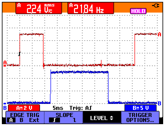
Here's a scope picture of the tach signal and one of the ignition-module drives from the EZK in our S4.
Chan-B (the blue trace) is the tach signal, 0-12 volts (5V/div). The rising edge is TDC, and the signal is a square wave with two cycles per engine revolution. This was captured at idle, around 650 RPM (22 hz).
Chan-A (red trace) is the drive signal (0-5v) to the left-side ignition module, the spark fires on the negative-going edge.
Our tach's both read accurately according to the ST2 so yours is a personal problem
Try it with a 12v square-wave.
Cheers, Jim
Idle timing.PNG
Thread Starter
Nordschleife Master
Joined: Jan 2009
Posts: 5,609
Likes: 84
From: MA
Tuomo, Here's a scope picture of the tach signal and one of the ignition-module drives from the EZK in our S4.
Chan-B (the blue trace) is the tach signal, 0-12 volts (5V/div). The rising edge is TDC, and the signal is a square wave with two cycles per engine revolution. This was captured at idle, around 650 RPM (22 hz).
Our tach's both read accurately according to the ST2 so yours is a personal problem
Try it with a 12v square-wave.
* The good news is that is seemed to have hte math figured out with 30 rpm / Hz.
* The tacho that I tested yesterday was about ok all the way until 5,000 rpm, but fell on it's face after that. I'll have to test it again with 12v amplitude to see if there's some weird interaction with required amplitude and rpm.
* "a personal problem." Buying a gauge from Ebay and finding out that it's not correctly calibrated is as surprising and disappointing as receiving a mail order bride just to find out that she's not a virgin...
Thread Starter
Nordschleife Master
Joined: Jan 2009
Posts: 5,609
Likes: 84
From: MA
The tacho is still off significantly, but it doesn't tilt. Work continues...
Thread Starter
Nordschleife Master
Joined: Jan 2009
Posts: 5,609
Likes: 84
From: MA
I now have two tachometers, one of which is accurate and another one that is not, after some adjustments from the top trim pot. Still working on making sense of the boost gauge...

Thread Starter
Nordschleife Master
Joined: Jan 2009
Posts: 5,609
Likes: 84
From: MA
- Make sure that you feed exactly the correct amplitude and offset square wave as signal. It's not like a modern digital computer, those parms actually impact the reading.
- If you have a function generator / oscilloscope with capture and replay functions, you may want to capture some actual signal from the car, compute the true rpm, and use that in claibration. I didn't do that.
- The top trim pot controls some weird mixture of gain and offset. The second trim pot seems to not control anything in the tacho, possibly it's for the boost gauge. Because of one degree of freedom, arbitrary calibration is not possible even if the instrument is linear. I take that back -- you can do an arbitrary calibration to a linear instrument if you're willing to take adjust the needle by taking it off and setting it to a little bit different position.
- It seems that the working tacho goes about accurately to about 7700 rpm. If you're interested in printing a face plate sticker, you can probably paint it from zero to 8000 rpm and make it still look the period. This would require no component changes. Mockup attached.
951Tach928Pod6.JPG