When you click on links to various merchants on this site and make a purchase, this can result in this site earning a commission. Affiliate programs and affiliations include, but are not limited to, the eBay Partner Network.
Nope, it'll stay as is. No paint. It's functional, and looks right to me.
The thin-wall stainless steel pipe that feeds the intercooler will be coated black. The boost pipes out of the intercooler will be painted silver, same as intake manifold.
While I agree that paint or powder coating is a bad idea, an anodized intercooler will not only be less noticeable, it will exchange heat better according to this article. http://www.aavid.com/product-group/e...ons-na/anodize
If you went with 2.5" ID racing springs on the front end you could run the pipe in behind the shock instead..... I think there is enough room. I will be doing this very thing but on the passenger side shortly. So it is interesting to see for sure.
I think that if you follow John's path and go thru the wheelwell, you'll want to map the wheel travel pretty carefully. When you map the wheel travel with the spring disconnected, I predict you'll learn that going under the shock-spring will have some complications and actually doesn't buy you that much in terms of the binding constraints.
Originally Posted by rnixon
Perhaps oval piping would help too.
If you choose to go under the shock-spring and use a hard pipe, triangular cross-section is probably the best. Oversized (for the required flow) round pipe pressed into that triangle shape will cause some pressure loss but it shouldn't be too bad.
Round pipe with gentle turns was John's choice based on casual back-of-the-envelope pressure loss estimates. If the maximum flow is not the only goal, there are some other options there as well.
While I agree that paint or powder coating is a bad idea, an anodized intercooler will not only be less noticeable, it will exchange heat better according to this article. http://www.aavid.com/product-group/e...ons-na/anodize
That's worth considering later, anodizing the cooler black. For now, we'll just run it bare.
Experience with racecars has taught me that much, so many conflicting requirements, you have to weigh up the pro's and con's of all scenarios and package everything to achieve the best result. there will be compromises, the trick is to know enough to know which ones carry the least penalty.
In terms of power production, this new system has a lot fewer compromises that hurt air flow capacity. It's dual 3.5"-3" inlets with gentle turns into compressors, true 2.5" outlets from compressor to very large intercoolers, then 2.5" expanding to 2.75" before the boost plenum box which itself has guide vanes and a machined bellmouths into the MAF. The exhaust manifold has only gentle turns and the wastegate has almost equal priority to the turbine.
No declaring of victory before the chickens are hatched and no counting of birds with bushes or whatever the English idioms are -- it's looking good to me at this point.
Originally Posted by Roy928tt
Packaging, it's all in the packaging....
Experience with racecars has taught me that much, so many conflicting requirements, you have to weigh up the pro's and con's of all scenarios and package everything to achieve the best result. there will be compromises, the trick is to know enough to know which ones carry the least penalty.
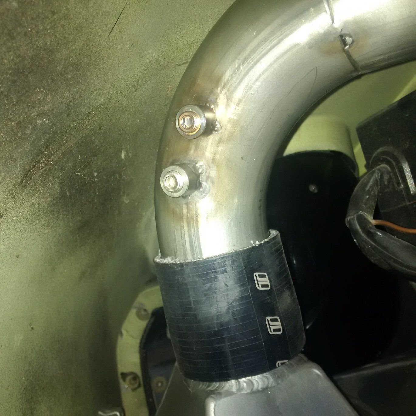
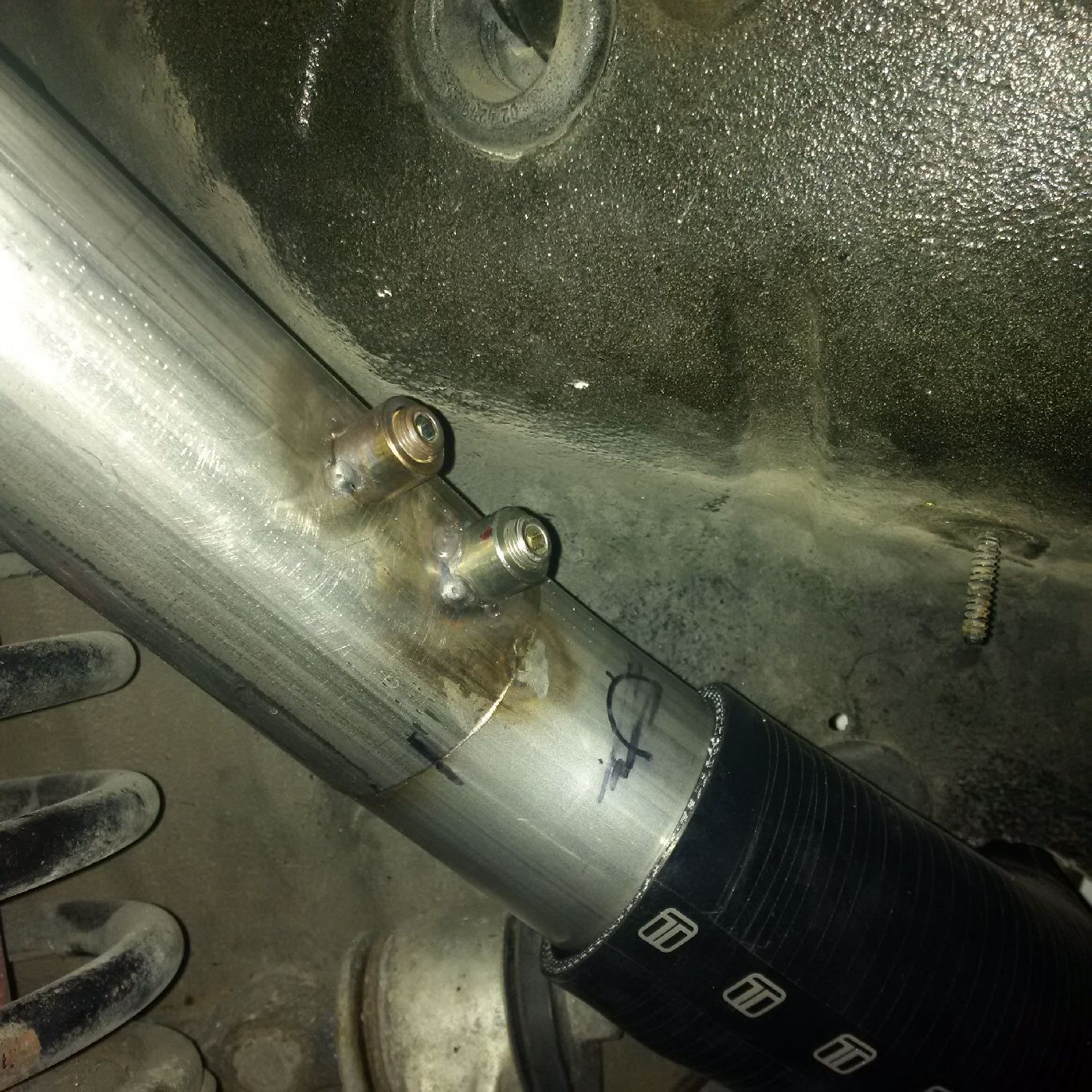
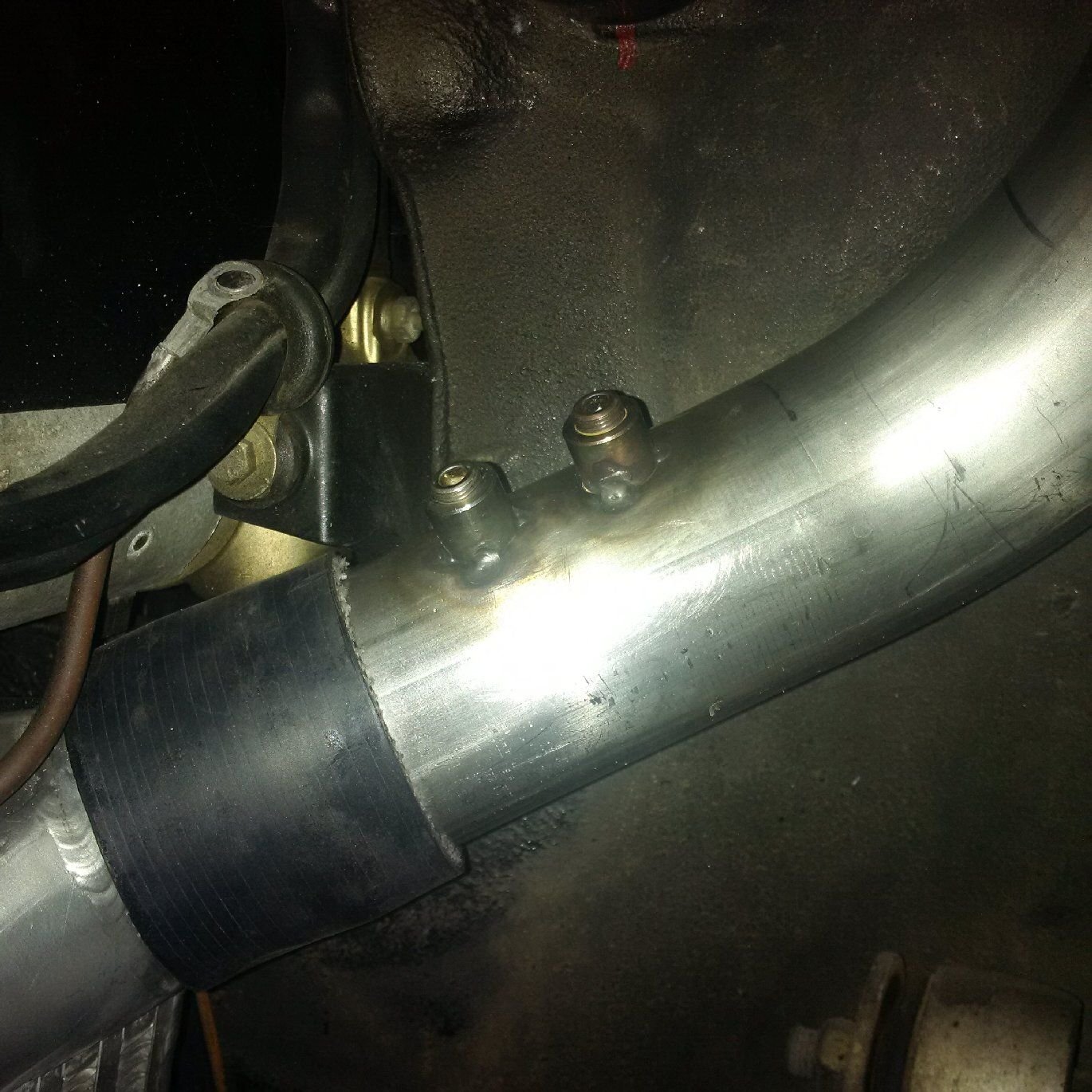
Need both the (stagnation) temperature as well as the static pressure in order to use the cross-sectional area and velocity (or mass flow)to compute all relevant data of what's going on inside the pipe. Hence two bungs, one for P and one for T.
The boost pipes are now tagged and documented and the next step is to final weld them, then coat them black for the desired visual effect. Inlet pipes next.
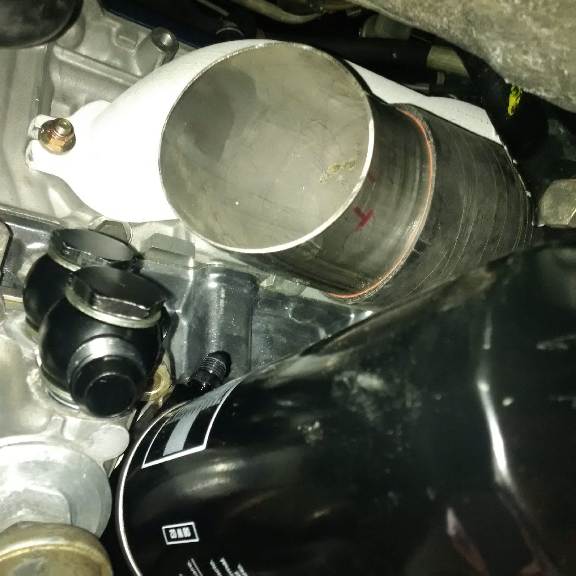
Turns out the next challenge is routing the oil lines to the oil cooler if the inlet pipes are sized at 3.5". Those pipes consume all volume near the block, 3.5" inlet pipe is massive, and complex. Photos later.
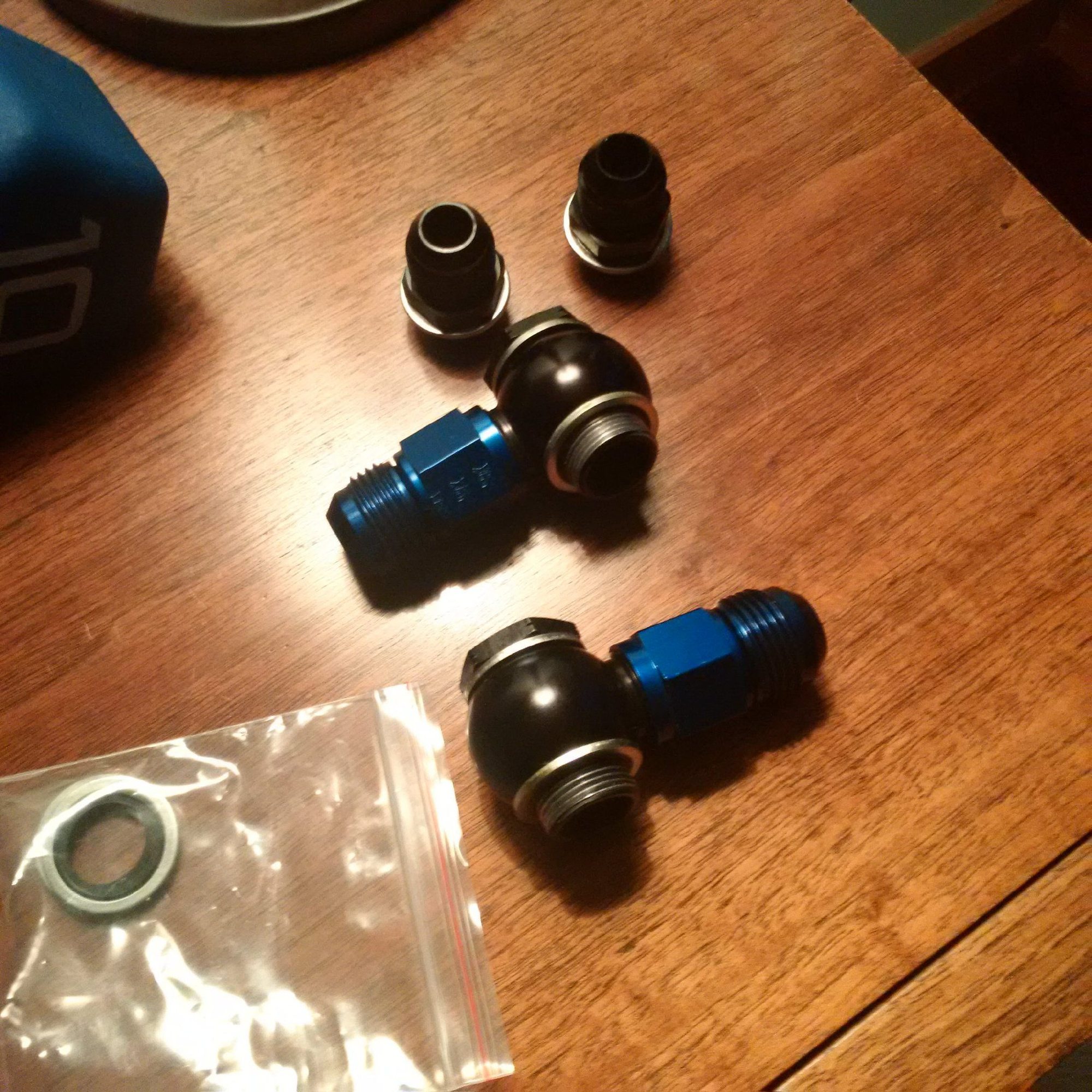
We need different fittings and hose ends to the oil cooler connection in the block because the lines have to hug the block running right next to it.
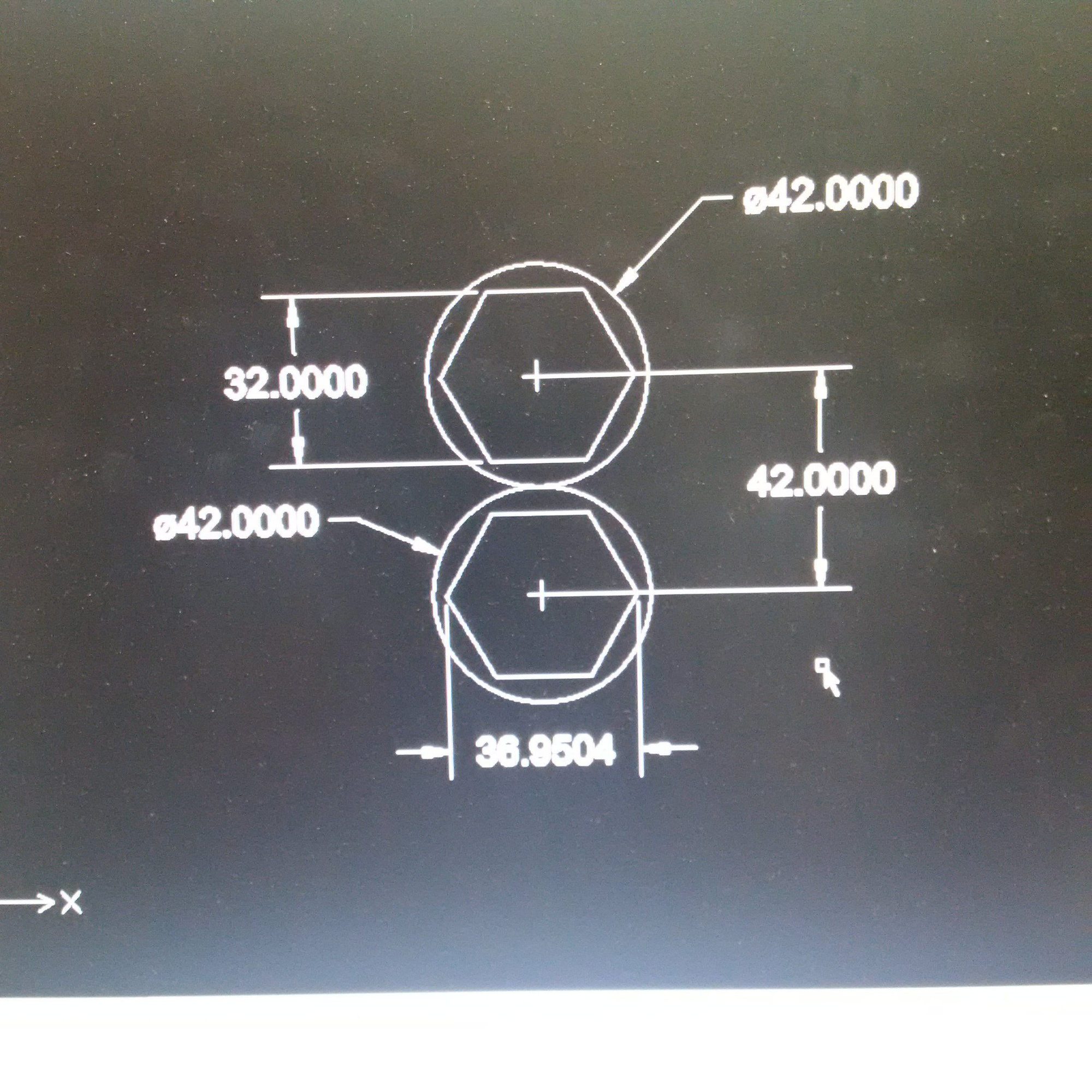
So here are the dimensions for the first candidates, -12an fittings. Less than zero tolerance (almost, but not quite, to the point of expelling a third grader saying that his teacher is "cute"):
Those aren't going to fit with about 38-38.2mm bore center distance on the block... ...back to the drawing board.
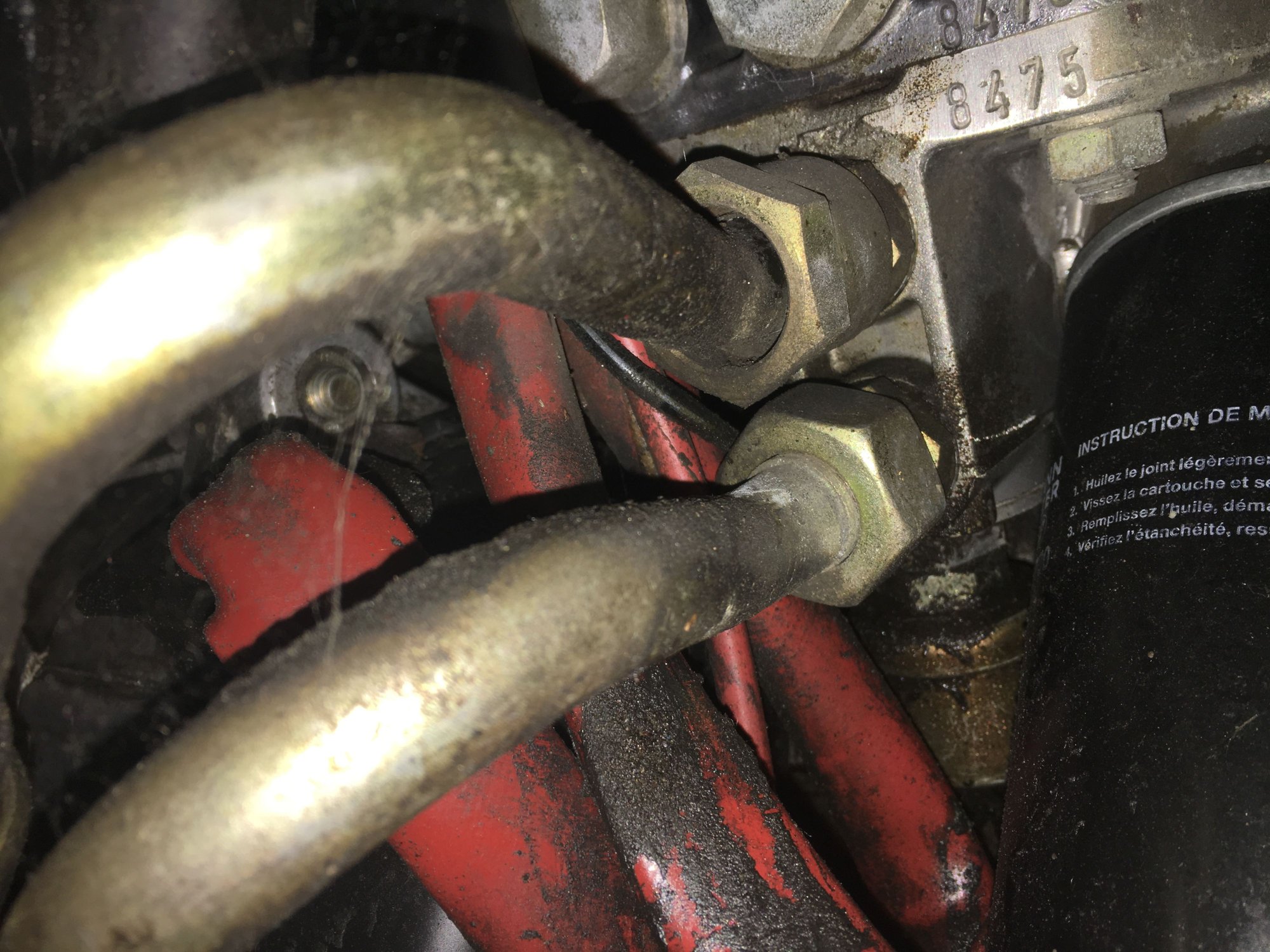
Here's a photo of the affected area from a loose stick engine with stock oil lines. These shoot out of the block precisely where the compressor inlet is supposed to be. And the flare nuts (or whatever the English word is) are real close to each other to start with:
Looks like it'll be -10AN lines throughout the oil-cooling circuit. The next step is to flow test all the fittings to make sure they have the required capacity for the cooling circuit.
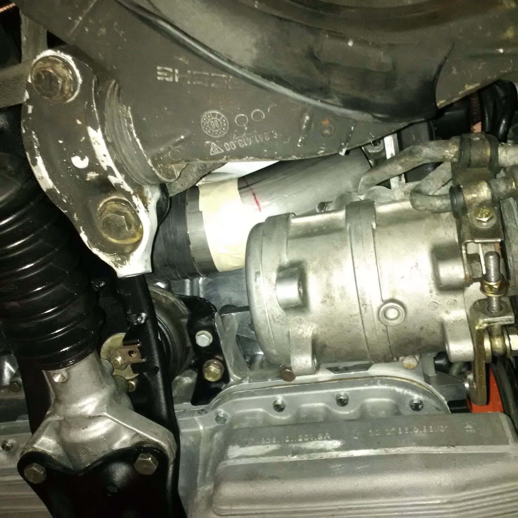
The driver side turbo inlet duct is difficult to fabricate for a number of other reasons relating to packaging. It will have curves and will have to be welded together from short 45-degree 4" CLR 3.5" OD turn segments. 3" OD pipe would be enough for perfectly straight duct, but because this section has to make complex turns the flow needs to be slowed down by increasing the diameter.
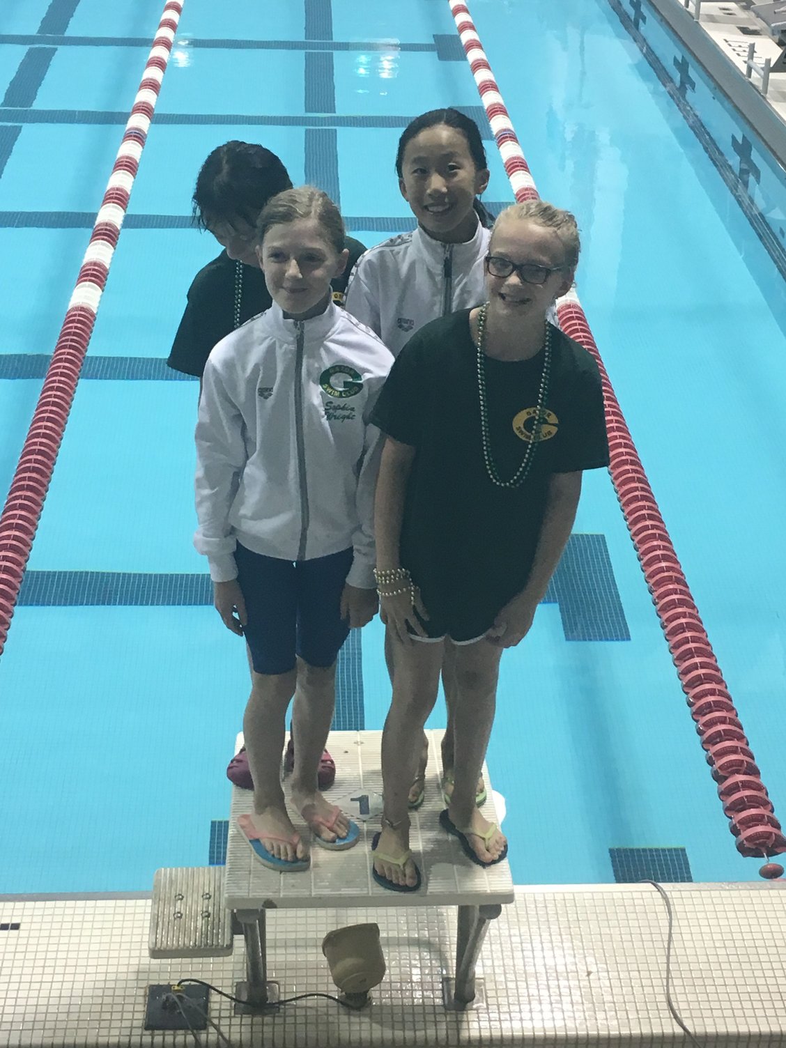
With the 3.5" inlet duct for the turbo there, that area around the block has less room for hose fittings than this first-place podium has room for four dominating relay swimmers:
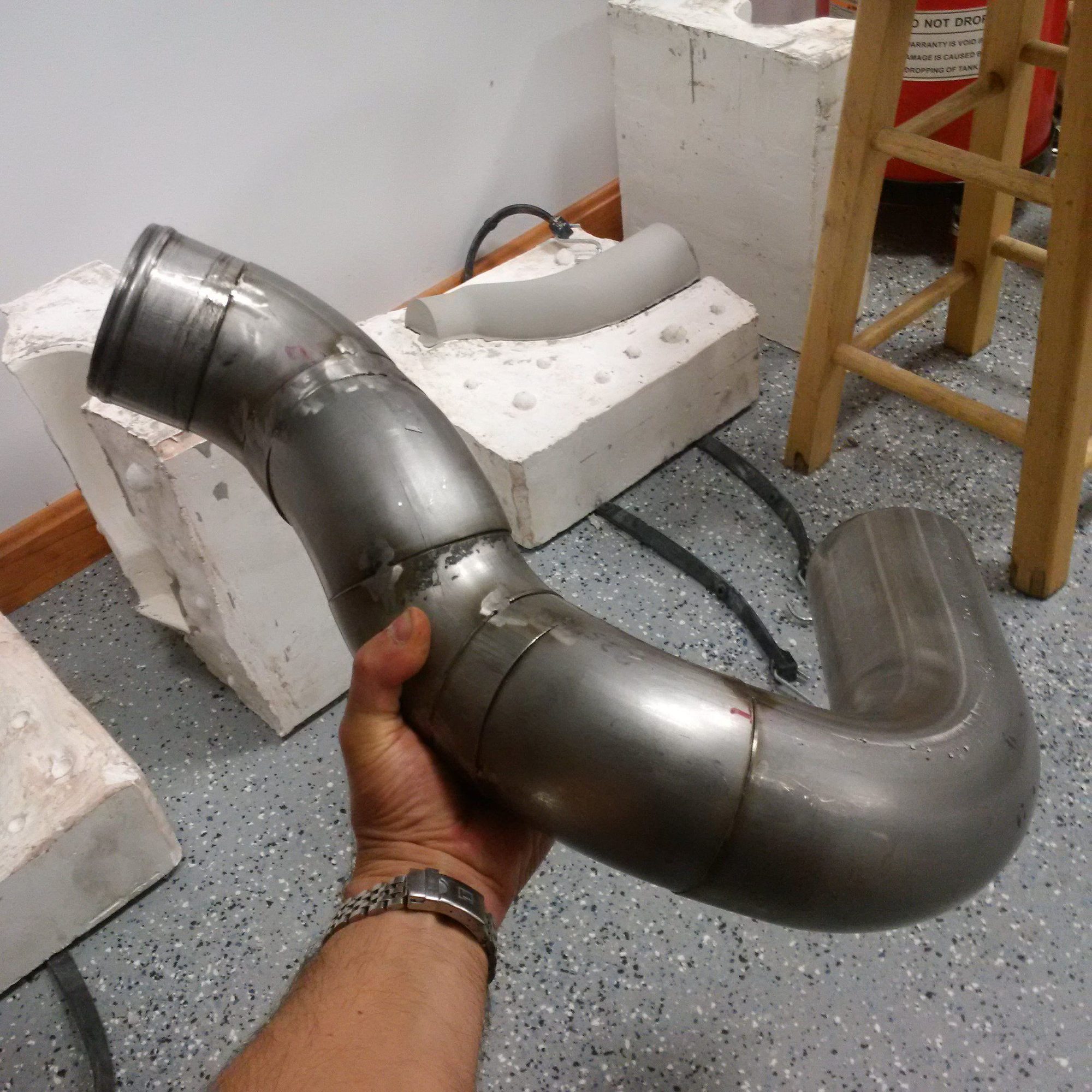
This is the constrictor boa from the driver side. It's got some bends, which make the 3.5" diameter a big plus. It'll go to final welding soon:
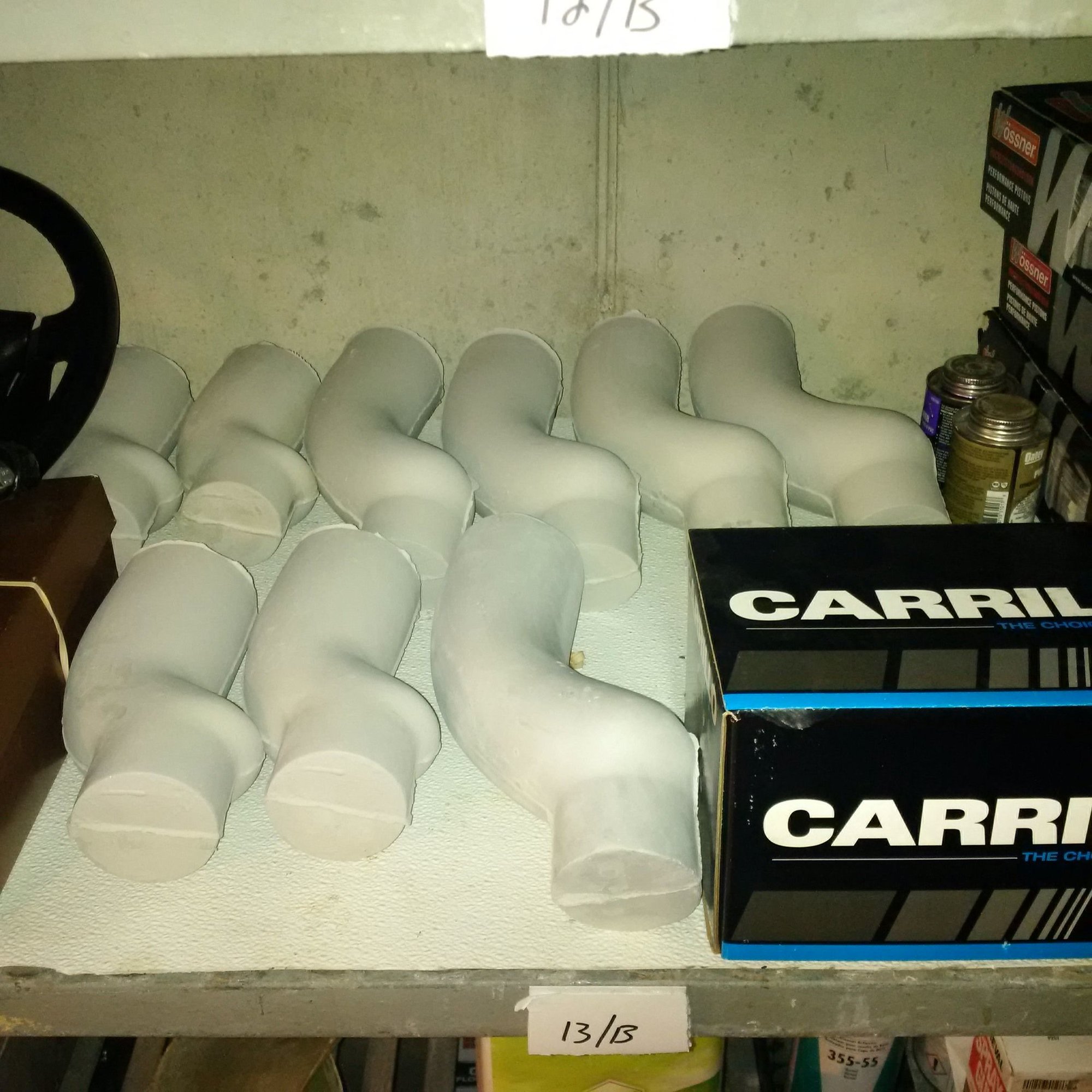
The fluoroline-silicone boots for the compressors inlets are produced using molds that will be destroyed in the wrapping process. Here's more of them cast:
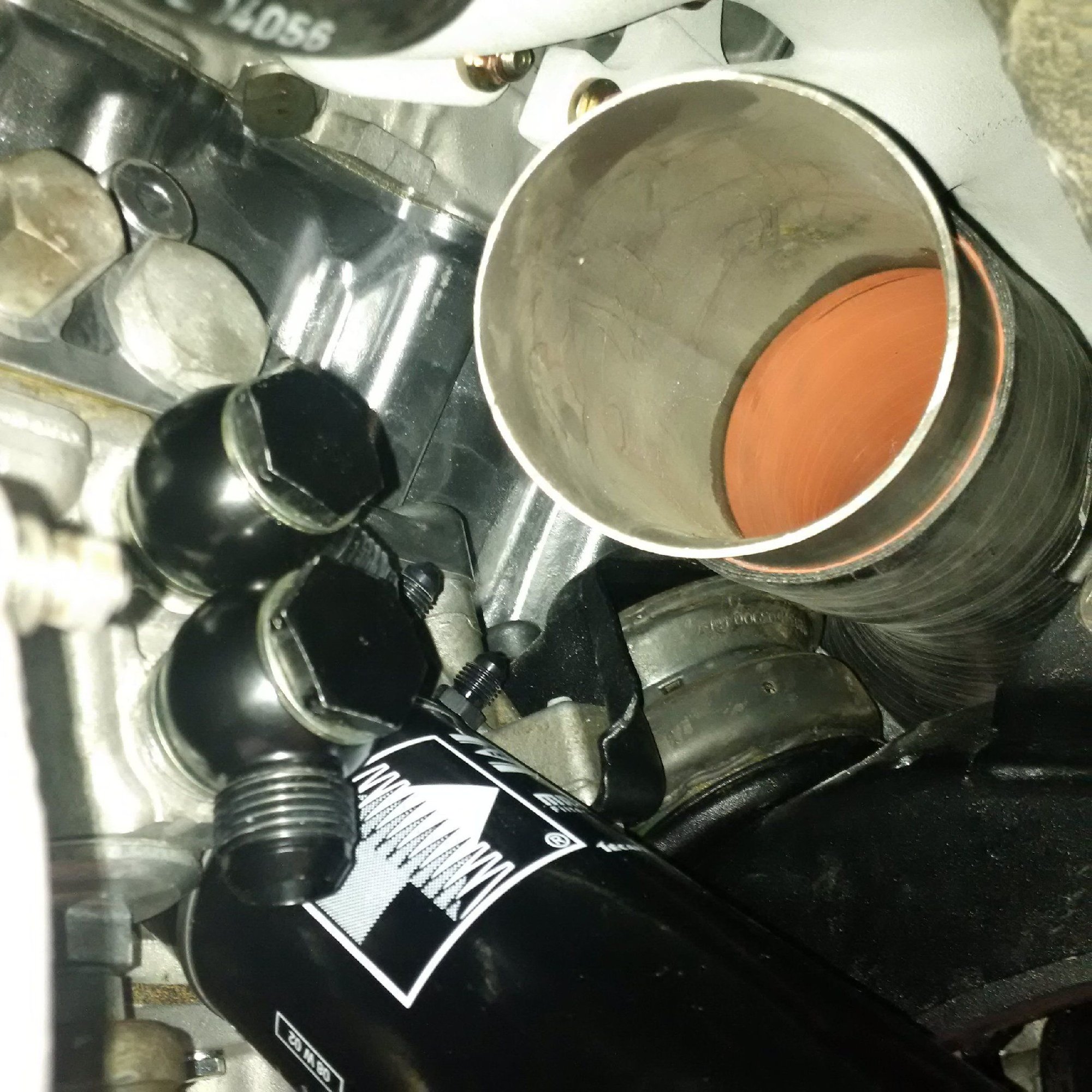
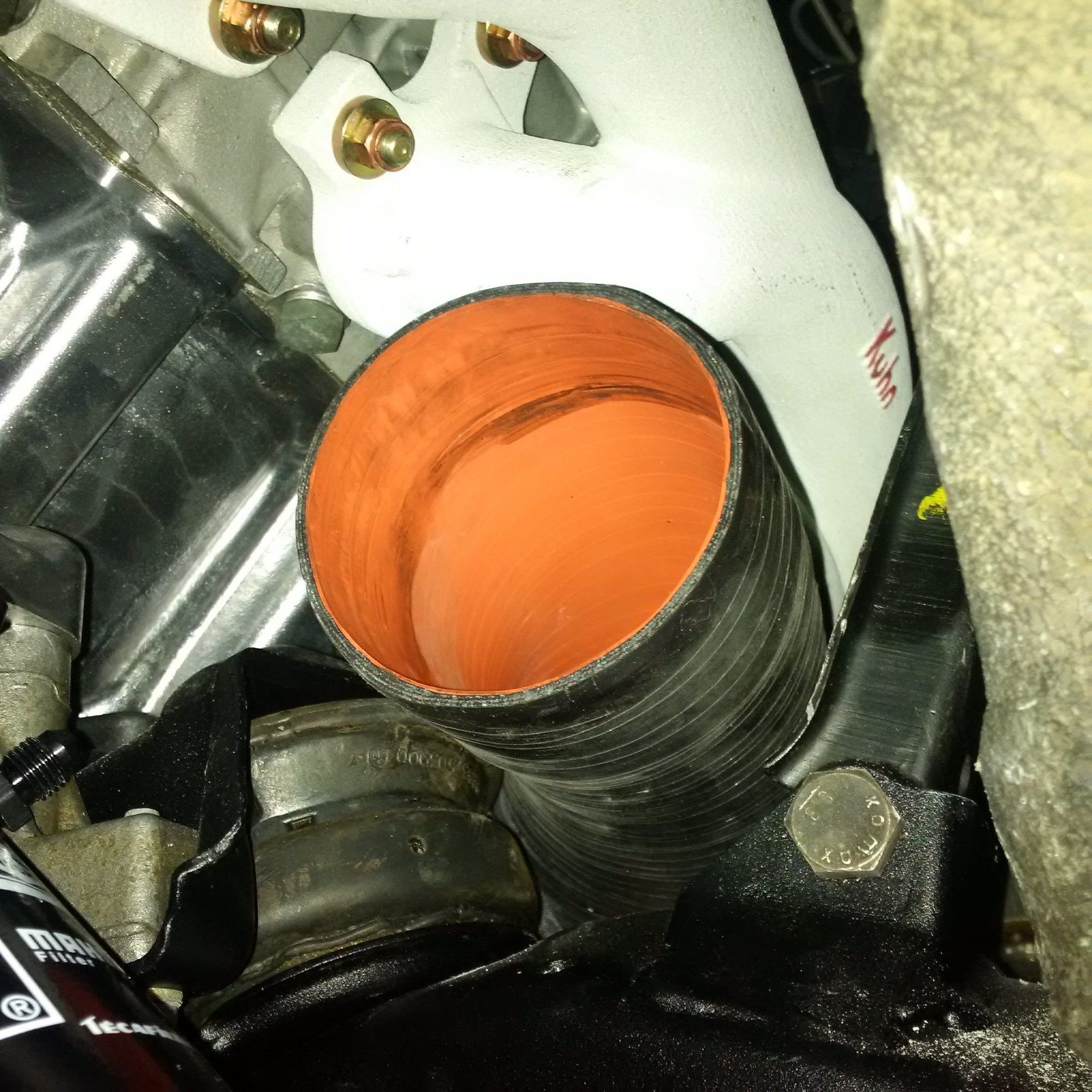
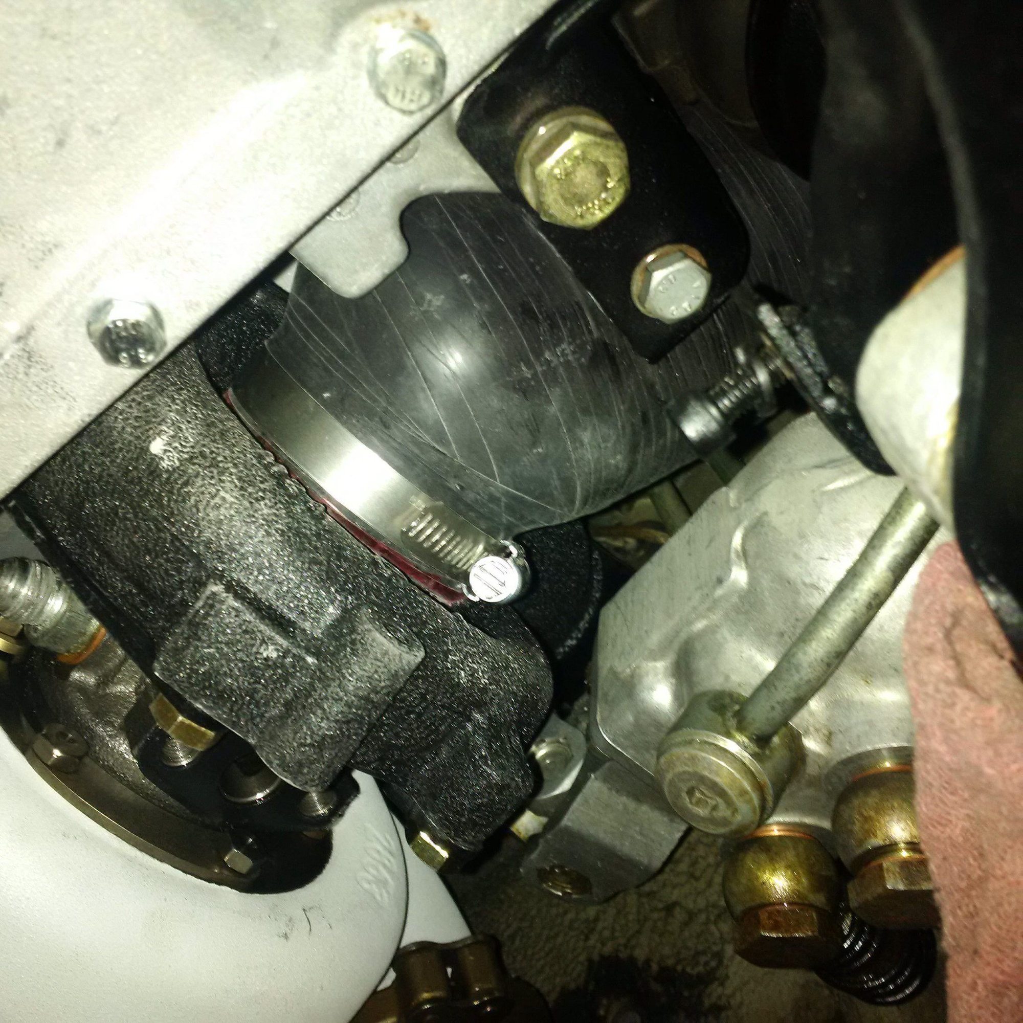
Here's a shot of the silicone boot in situ. The heat shield between the silicone boot and the exhaust manifold will still need to be fabricated. The likely fastening mechanism for the heat shield is the clamps at the both ends of the boot, it should work nicely and not vibrate if supported from both ends.
There's good access to the clamps for installation:
This is the work in progress on passenger side:
The filter element with the metal plate. The filter needs some custom work, but the flow rate / pressure loss will be very favorable in the end with all this extra area:
Man that major disassembly for any maintenance.
I made everything to be able to be disconnected with joins , in the race car so I can rotate engines , to check for wear and any maintenance, what you have shown is a nightmare , congratulations on being so brave.


 07-12-2016 | 01:12 AM