
Another way to support the engine, to do a MM/pan gasket
 04-06-2010, 09:12 PM
#1
Team Owner
Thread Starter
I finally took some pictures of the engine support I use for MM/OPG replacement.
Use at your own risk .
It does work rather well and the oil pan can be removed and replaced and all but 4 bolts can be installed with these supports in place .
I have done 12 MM/OPG jobs so far using this system.
To make the supports first have the car jacked up and supported on the 4 jack pads.
Then remove the alternator from its position as well as the oil filter and remove as many oil pan bolts as you can save for the few the are above the crossmember.
Jack the engine up so the oil pan is flush with the crossmember.
Then measure the distance from the alternator support to ground and the AC compressor mount to ground, cut your boards accordingly.
Make a small notch in the inner portion of the board for the cradle bolt on the alternator side so the board will fit onto the cradle.
Use the floor jack under the oilpan with a board to spread the load, when your ready to remove the crossmember move the jack to under the Xmember then lower it down, remove the harness clamp on the left side of the Xmember then remove the Xmember.
Thenput the jack under the oilpan, then remove the 4 remaining oilpan bolts and lower the pan down with the jack,
slide the jack forward with the pan on it be careful not to hit the supports replace all of the necessary parts then refit using the jack to lift the pan then fit all of the bolts that you can except for the ones that are blocked by the supports, ( note make sure to remove the bolts by the supports before fitting the supports or you wont be able to remove the pan.)
Note the steering rack is just dropped down the only parts your need to remove are the 2 banjo bolts and loosen the fenderwell hose clamp so the hoses can slide some drain the rack and slide it to the rear of the car, dont remove the steering shaft coupler.
Note if one of the supports should come free the engine will fall sideways and rest on the side fenderwell ,also there is a support under the front of the TT that will also catch the engineTT assembly dont let the enfgine rest on the front support for any amount of time as its not made to hold this weight but will provide a safety net
 04-06-2010, 09:31 PM
#2
Three Wheelin'
Join Date: Mar 2010
Location: Colorado Springs, CO USA
Posts: 1,307
Likes: 0
Received 3 Likes
on
3 Posts
Good idea.
Is this the current state of your car? Mine's resting on the new mounts, but I still need to torque everything down, reinstall the rack and sway bar, and the compressor, and the oil filter, and the condensor, and the undertray....
And the weather's been pretty nice (other than the wind!) in Colorado the last couple of days. Can't wait to get things back together and out of the garage!
Cheers,
Paul
04-06-2010, 09:49 PM
#3
Team Owner
Thread Starter
This is a customers car, i have kept forgetting to take pictures of my jobs , and this is one that i finally took the time to take pictures of
04-06-2010, 10:39 PM
#4
Drifting

Good job. You've used the pan to jack the engine higher I suppose. I have jacked the body and then lowered the car on the lower supports, which I placed under the clutch housing.
I used two adjustable jack stands carefully placed under the clutch housing with metal shims for fine adjustment. Care must be taken when lowering the body (and at the same time, lifting the engine off the crossmember motor mount pads) on these stands, as the O2 sensor can interfer with the body can cause O2 sensor damage.
I used two adjustable jack stands carefully placed under the clutch housing with metal shims for fine adjustment. Care must be taken when lowering the body (and at the same time, lifting the engine off the crossmember motor mount pads) on these stands, as the O2 sensor can interfer with the body can cause O2 sensor damage.
04-06-2010, 11:12 PM
#5
Nordschleife Master
That's unsafe.
I lift the engine with my engine hoist. Gotta clamber around the legs a bit, but I can maveuver the engine when putting the X-member back on and it's not going to fall.
I lift the engine with my engine hoist. Gotta clamber around the legs a bit, but I can maveuver the engine when putting the X-member back on and it's not going to fall.
 04-07-2010, 03:13 AM
#7
Shameful Thread Killer
Rennlist Member
Rennlist Member
A bottle jack and a few chunks of wood on the lower trans cover works fine. If the trans cover is off, jack with a bit of wood on the housing behind the flex plate.
Trending Topics
04-07-2010, 05:49 AM
#8
Drifting
I need to do the mounts soon and was wondering about how to change the OPG as I intended to support the pan with bottle jack (don't have engine hoist). Your method sounds like it fixes the problem!
TIA
04-07-2010, 08:32 AM
#9
Rennlist Member
Please could you indicate with reference to PET, or a photo, where you mean by the lower trans cover?
I need to do the mounts soon and was wondering about how to change the OPG as I intended to support the pan with bottle jack (don't have engine hoist). Your method sounds like it fixes the problem!
TIA
I need to do the mounts soon and was wondering about how to change the OPG as I intended to support the pan with bottle jack (don't have engine hoist). Your method sounds like it fixes the problem!
TIA
I need to do it on my 84 and the GTS...
Thanks! / Bruce
04-07-2010, 09:44 AM
#10

My first OPG/MM job had supports under each MM mount point, with a third emergency support just under (not touching) the fly wheel pulley. Lots of stuff in the way though. My second OPG/MM job employed the familiar wood supports resting on the inner fender ledges, with huge eye bolts hanging down to the engine lift points. Wasn't hard or time consuming to set up. Much less was in the way and it was a bit more secure feeling. Since then I've had a bizarre (but low impact) accident involving lifting and have adopted a much more safer-than-sorry approach. Weird stuff can happen.
04-07-2010, 09:56 AM
#11

Just go to http://www.northerntool.com/shop/too...9403_200309403 and spend the $100.00. When you are finished, if you no longer want it, sell it on craigslist for $80.00.
04-07-2010, 10:43 AM
#14
Supercharged
Rennlist Member
Rennlist Member
Join Date: May 2002
Location: Back in Michigan - Full time!
Posts: 18,925
Likes: 0
Received 59 Likes
on
33 Posts
BTW, here's what my setup looks like.
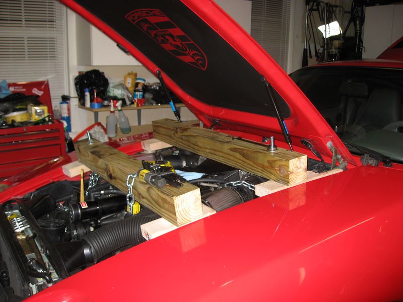
Shopping list:
1 - 8' 4x4
1 - 6' 2x4 (I actually had scrap laying around)
4' - chain
4 - master links (I think this is the most expensive part)
2 - Eye bolts (I forget what size, I think they were 1/2" x 8")
2 - Nuts to fit the eye bolts
2 - washers
Shopping list:
1 - 8' 4x4
1 - 6' 2x4 (I actually had scrap laying around)
4' - chain
4 - master links (I think this is the most expensive part)
2 - Eye bolts (I forget what size, I think they were 1/2" x 8")
2 - Nuts to fit the eye bolts
2 - washers
Last edited by AO; 04-07-2010 at 02:05 PM.
04-07-2010, 10:51 AM
#15
Rennlist Member
My engine hung on this for nearly a month. It was very sturdy and I felt safe under it. There was nothing in the way at any time. The engine now rests on its new mounts with everything but the rear lower control arm and sway bar bushings tightened.
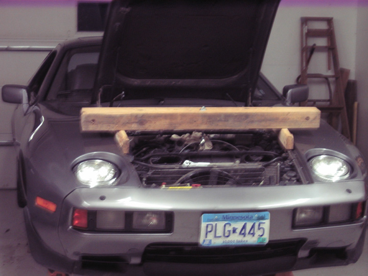
The side supports are a 2 x 6 ripped in half and screwed to the 4 x 4. They have counter bores that fit over the fender bolts which keep them from sliding.
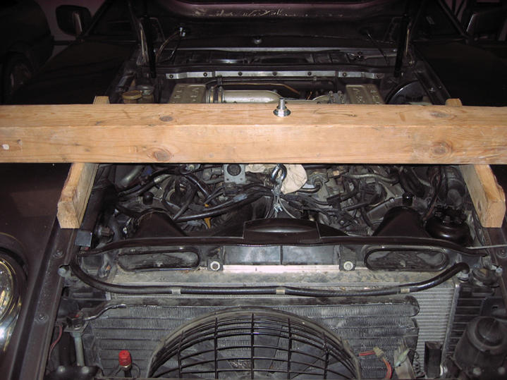
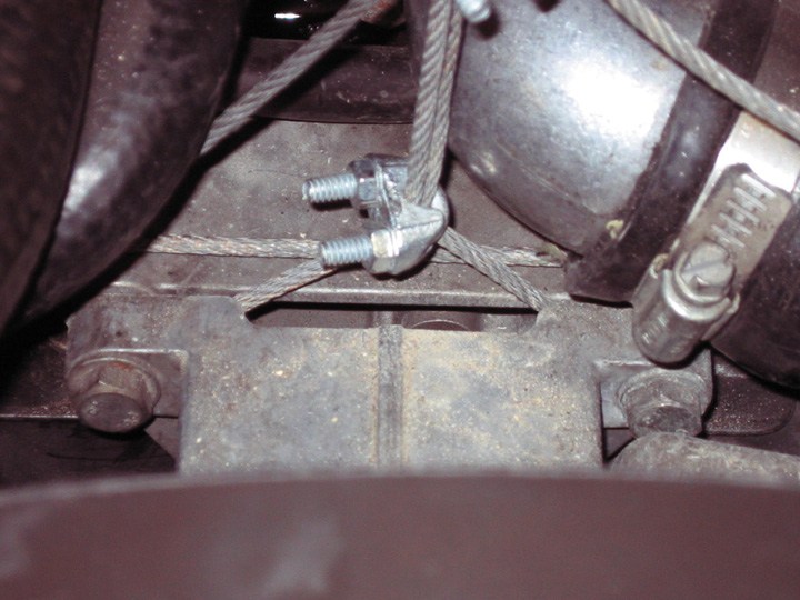
Be sure to use strong enough cable. Mine was 1/8 inch 7 x 7 galvanized which has a breaking strength of 1700 pounds. Make sure the clamps are installed properly. If put on backwards they can slip.
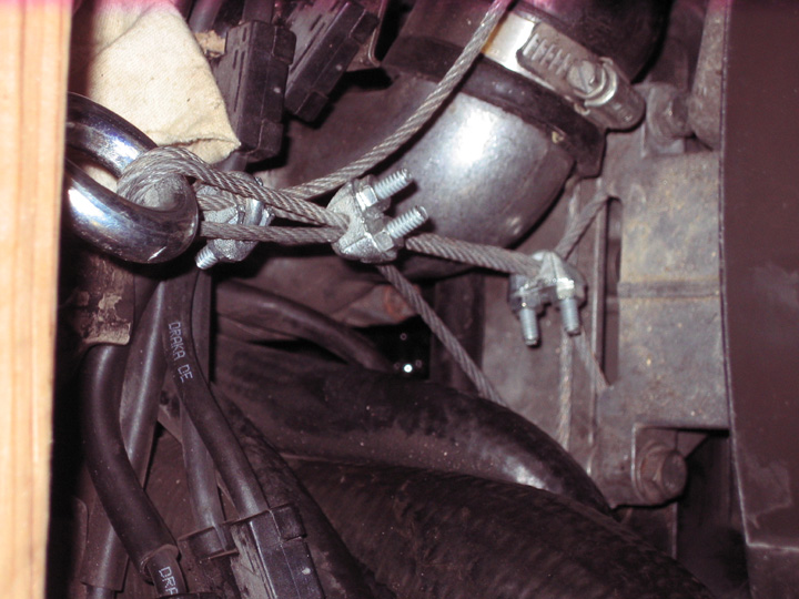
The bottom clamp is merely a yolk to keep the cable from hitting the thermostat housing. Notice how the cable is holding �at the bolts� so the arm doesn�t act as a lever.
The side supports are a 2 x 6 ripped in half and screwed to the 4 x 4. They have counter bores that fit over the fender bolts which keep them from sliding.
Be sure to use strong enough cable. Mine was 1/8 inch 7 x 7 galvanized which has a breaking strength of 1700 pounds. Make sure the clamps are installed properly. If put on backwards they can slip.
The bottom clamp is merely a yolk to keep the cable from hitting the thermostat housing. Notice how the cable is holding �at the bolts� so the arm doesn�t act as a lever.
