

Fuel pump controller from a light dimmer
 07-11-2009, 03:38 PM
#1
Nordschleife Master
Thread Starter
Here are a couple of cell phone photos of my attempt to produce a fuel pump control signal using the MAF signal.
First, background. I will be using the new generation Fuelab Prodigy fuel pump. That pump can pump out 170+ gallons per hour, which would exhaust the fuel return line in almost all circumstances. The good news is that the Prodigy pump accepts a pulse-width-modulation (PWM) signal that allows controlling the flow rate.
Since the air fuel mass ratio is about constant, and certainly within the range from 10 to 18, a natural signal source for the pump is the MAF signal. It would be nice to have the pump run hard only when the engine is ingesting air at a rapid rate. The 928 MAF signal is nominally 0-5V output which in practice fluctuates in the range 1.5V-5.5V most of time. The practical problem remains converting the 0-5V analog signal to PWM signal and include a couple of trims and adjustments in the conversion.
So here's what I did. I bought a light dimmer kit from Velleman. Kit number is K8004. It doesn't have a Porsche logo on it, so it was $20 + $8 for shipping. I also ordered an aluminum box from the web for about $10 + shipping, and then a couple of bags of waterproof connectors. I had grommets and wire already. So, we're looking about a $50 budget here.
The end result is an adjustable analog to PWM converter packaged in a way that is at least splash proof. Photos below.
Here's the starting point. The kit is quick to put together, instructions are very clear, and soldering is made easy by the layout.
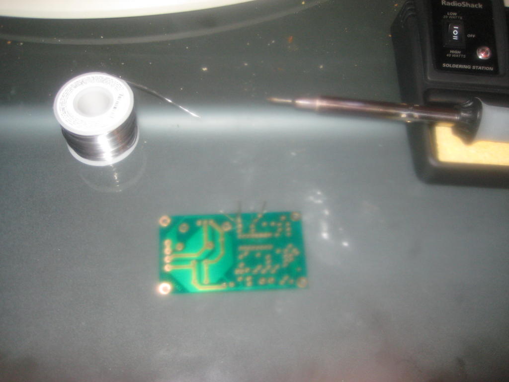
Next, it was time to test the complete converter. The RadioShack multimeter has PWM duty cycle logic in it, which makes this testing very simple. I followed the test plan that came with the kit and added a couple of my own. The kit worked without any adjustments or fixes.
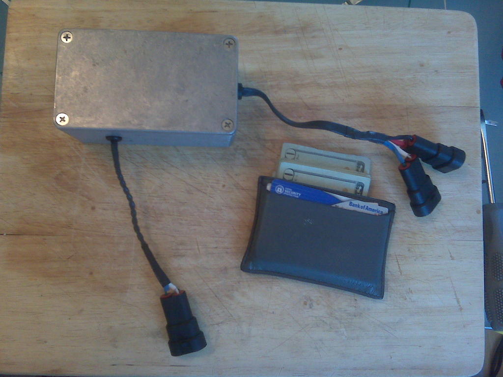
The box is a little bit of an overkill, it's a sealed waterproof electronics box. I drilled two holes and pushed modified Jegs grommets into the holes. Next, I pushed the shrink wrap and wire thru the grommet.
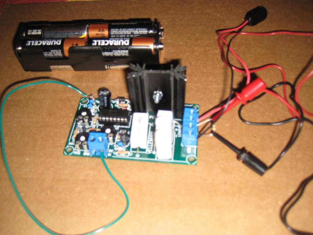
Notice the three pots in converter. These control PWM sensitivity, frequency, and offset. Offset is the minimum duty cycle that will be coming out the converter even if there's no input signal (or it's grounded). I set the frequency to about 1 kHz. The sensitivity now gets up to about 90% duty cycle when the input signal is about 5V.

Wiring is very easy, because the kit has short-circuit protection and overload protection. Since we are only moving data here and not actually powering the pump, thin wires will work just fine.
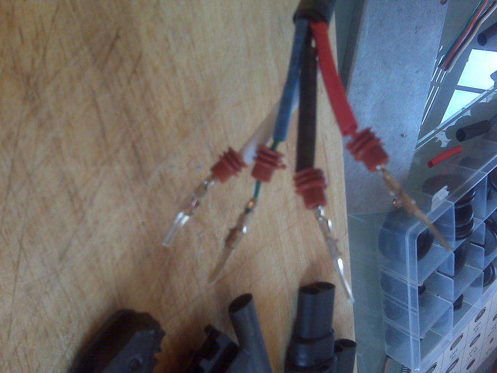
I terminated the wires to three waterproof (or at least my source in Hong Kong claims these are waterproof) female connectors. Both the MAF in and PWM out include a signal ground wire. I had to come up with my own color coding standard which is universally applied in my household today.
Red: DC in positive
Black: DC ground
White: Signal positive
Blue or green: Signal ground
Here's the finished converter, my nearly empty wallet next to it give scale:
Over the next couple of weeks, we'll see if this works in the car. I think it will. Alternatively, the Porsche may turn in to a literal "bondfire of vanities."
First, background. I will be using the new generation Fuelab Prodigy fuel pump. That pump can pump out 170+ gallons per hour, which would exhaust the fuel return line in almost all circumstances. The good news is that the Prodigy pump accepts a pulse-width-modulation (PWM) signal that allows controlling the flow rate.
Since the air fuel mass ratio is about constant, and certainly within the range from 10 to 18, a natural signal source for the pump is the MAF signal. It would be nice to have the pump run hard only when the engine is ingesting air at a rapid rate. The 928 MAF signal is nominally 0-5V output which in practice fluctuates in the range 1.5V-5.5V most of time. The practical problem remains converting the 0-5V analog signal to PWM signal and include a couple of trims and adjustments in the conversion.
So here's what I did. I bought a light dimmer kit from Velleman. Kit number is K8004. It doesn't have a Porsche logo on it, so it was $20 + $8 for shipping. I also ordered an aluminum box from the web for about $10 + shipping, and then a couple of bags of waterproof connectors. I had grommets and wire already. So, we're looking about a $50 budget here.
The end result is an adjustable analog to PWM converter packaged in a way that is at least splash proof. Photos below.
Here's the starting point. The kit is quick to put together, instructions are very clear, and soldering is made easy by the layout.
Next, it was time to test the complete converter. The RadioShack multimeter has PWM duty cycle logic in it, which makes this testing very simple. I followed the test plan that came with the kit and added a couple of my own. The kit worked without any adjustments or fixes.
The box is a little bit of an overkill, it's a sealed waterproof electronics box. I drilled two holes and pushed modified Jegs grommets into the holes. Next, I pushed the shrink wrap and wire thru the grommet.
Notice the three pots in converter. These control PWM sensitivity, frequency, and offset. Offset is the minimum duty cycle that will be coming out the converter even if there's no input signal (or it's grounded). I set the frequency to about 1 kHz. The sensitivity now gets up to about 90% duty cycle when the input signal is about 5V.
Wiring is very easy, because the kit has short-circuit protection and overload protection. Since we are only moving data here and not actually powering the pump, thin wires will work just fine.
I terminated the wires to three waterproof (or at least my source in Hong Kong claims these are waterproof) female connectors. Both the MAF in and PWM out include a signal ground wire. I had to come up with my own color coding standard which is universally applied in my household today.
Red: DC in positive
Black: DC ground
White: Signal positive
Blue or green: Signal ground
Here's the finished converter, my nearly empty wallet next to it give scale:
Over the next couple of weeks, we'll see if this works in the car. I think it will. Alternatively, the Porsche may turn in to a literal "bondfire of vanities."
 07-11-2009, 05:36 PM
#2
Three Wheelin'
Might work. Be sure the input to the light dimmer doesn't load the output of the MAF and change the MAF voltage to the LH/EZ-K. MAF output at idle is around 2.8 volts, 3 volts with cold engine.
 07-11-2009, 06:54 PM
#4
Nordschleife Master
Thread Starter
It doesn't draw any measurable amount of current. About the same as an opamp signal in.
07-11-2009, 08:23 PM
#5
Nordschleife Master
I remember looking over that pump and thinking about trying some kind electronic fuel pressure regulation, but ended up deciding against any side projects. Some kind of fixed return line restriction, a pressure sensor, and the fuel pressure could be electronically set.
BTW maybe an interesting source for a signal would be the injector pulse, plenty of current, and directly related to fuel consumption.
BTW maybe an interesting source for a signal would be the injector pulse, plenty of current, and directly related to fuel consumption.
07-11-2009, 08:58 PM
#7
Nordschleife Master
Thread Starter
However, recall what I am using this for and how.
I have a pump with an internal controller that uses a PWM signal as a control input. The Ruth Goldberg machine I whipped up is simply translating an analog data signal into a PWM data signal, not to a PWM power source. The actual power circuitry is inside the fuel pump and this effort has nothing to do with it. The pump's internal controller that receives the PWM signal draws virtually no current from the PWM signal line. When installed, the whole converter that you see in the pictures could operate a month with 8 AA batteries.
Trending Topics
07-11-2009, 09:50 PM
#8
Rocket Pilot
Rennlist Member
Rennlist Member
Join Date: Apr 2004
Location: gettysburg pa.
Posts: 3,298
Likes: 0
Received 0 Likes
on
0 Posts
Bell engineering and others already sell devices like this. Cool though if you can manufacture your own. I wish I knew more about that stuff. Good job.
 07-12-2009, 04:16 AM
#11
Nordschleife Master
Thread Starter
 07-12-2009, 12:08 PM
#14
Nordschleife Master
Thread Starter
You should consider two options then.
First option, run the second pump based on a Hobbs switch so that it only comes on when boost is over certain threshold. This kit can be adapted pretty easily for a second fuel pump. http://www.racetronix.biz/customkiti...sp?kc=CEPH&eq=
Second option, get a real PWM power controller so you can run the second or both pumps based on something like the MAF signal.
07-12-2009, 12:52 PM
#15
Nordschleife Master
Tuomo,
I may consider running a boost switch to override the switches and turn on the second pump. However I plan on being able to manually activate it, along with the higher boost setting which will need the fuel.
I will not be running a stock EFI system, nor will I have any stock wiring in the car. This car will have the absolute minimum on it.