When you click on links to various merchants on this site and make a purchase, this can result in this site earning a commission. Affiliate programs and affiliations include, but are not limited to, the eBay Partner Network.
I also don’t get it why I couldn’t recover dynamic pressure from the free stream flow into static pressure by stagnating it in a submerged duct.
First, as mentioned before there will be no dynamic pressure to recover via stagnation if the air isn't flowing down the ramp and through the duct inlet to begin with. And that only happens if the pressure in the engine bay is less than the static pressure above the duct. This again is only the case if using the engine intake as a vacuum source.
Originally Posted by ptuomov
I agree with you that when flow is zero, dynamic pressure is zero and total pressure is equal to static pressure. I think however that it does matter how we get to zero flow. If we efficiently stagnate the flow, we recover the dynamic pressure into static pressure. If we do it inefficiently, or point the duct perpendicular to flow, we just get the static pressure of the free stream flow.
Again if the flow is zero at the duct inlet (i.e. stagnation) there is no air going into the engine bay. And that is what we are discussing here. How to get air into (and through) the engine bay or into the intake ducts.
Again if the flow is zero at the duct inlet (i.e. stagnation) there is no air going into the engine bay. And that is what we are discussing here. How to get air into (and through) the engine bay or into the intake ducts.
I 100% agree.
Now, using the 85% pressure recovery efficiency assumption and your example pressure values at 100mph, I got a guesstimate of 35 SCFM of flow per square inch of the duct MSCA into the engine bay. This was with the critical (and possibly untrue) assumption that the engine compartment has ambient pressure. Do you agree in principle that this is a valid computation? Do you agree in practice that 35 SCFM per square inch of MSCA is a level of flow that could support the 85% pressure recovery efficiency assumption?
Now, using the 85% pressure recovery efficiency assumption and your example pressure values at 100mph, I got a guesstimate of 35 SCFM of flow per square inch of the duct MSCA into the engine bay. This was with the critical (and possibly untrue) assumption that the engine compartment has ambient pressure. Do you agree in principle that this is a valid computation? Do you agree in practice that 35 SCFM per square inch of MSCA is a level of flow that could support the 85% pressure recovery efficiency assumption?
No. Again the pressure recovery percentage is based on the percentage of dynamic pressure flowing through the duct. With no flow there is no recovery. And if the engine bay is at ambient pressure than there will be no flow since the duct at point #5 is in a region of static pressure that is less than ambient.
No. Again the pressure recovery percentage is based on the percentage of dynamic pressure flowing through the duct. With no flow there is no recovery. And if the engine bay is at ambient pressure than there will be no flow since the duct at point #5 is in a region of static pressure that is less than ambient.
I�ll just have to go back to studying this because that makes no sense to me. What would make sense to me is that NACA duct works as long as its pressure recovery efficiency coefficient is larger than the negative of the (static) pressure coefficient in that Porsche graph. In other words, it would make sense to me if NACA ducts would work on the hood but would work on the roof panel right next to the windshield edge. But instead of debating that here, let me spend some time learning more over the weekend.
Gt6er is the authority on this, but the easiest way lacking a wind tunnel is to put small drops of gear oil on the car the next time you run it. Note or take pics of the streak pattern. Redneck wind tunnel. A version of "tufting" where yarn is taped in grid patterns and photographed in the wind tunnel.
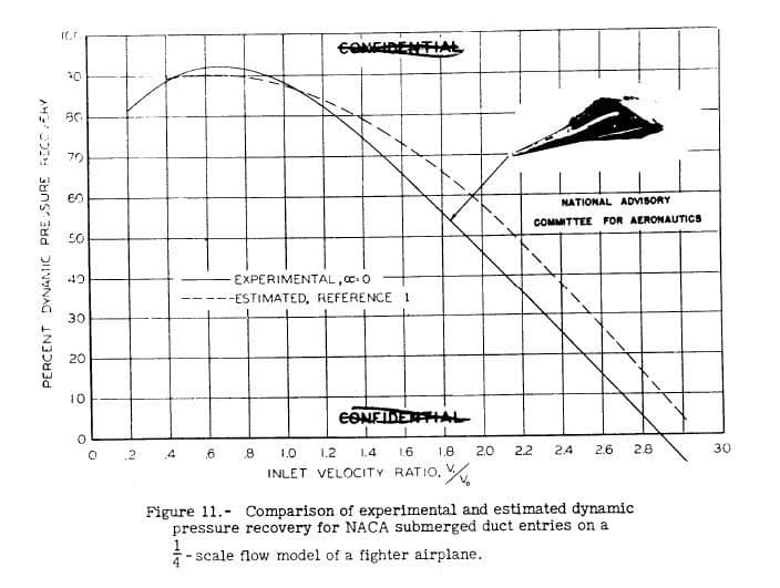
I now understand better why a second blower in that NACA test setup is fairly important. The efficiency of the NACA duct is dependent on the velocity ratio, the ratio of air flow speed thru the duct to the free air stream speed. 0.7 being close to optimal velocity ratio and 0.5-1.5 being a range of reasonable efficiency.*
Returning to the example. Ambient pressure in the engine compartment. 100 mph car and thus free stream speed. NACA duct is at the point #5 which has a Cp of -0.25. An 85% efficient NACA duct would result in 0.113 psi over ambient. 0.113 psi pressure differential would support about 35 SCFM per sqin of air flow, at velocity of about 57 mph. This gives a velocity ratio of 0.57, which is in the range of NACA duct velocity ratios for which 0.85 efficiency is reasonable, .
It's still an open question to me how the NACA duct performs if the outlet is directed to a sealed bottle and the velocity ratio is zero. Will it be more like a pitot tube or more like a static tube, or something in between?
* Apparently, "NACA R.M. No. A8B16 , p. 34, shows ram recovery (also called pressure recovery) greater than 90% for mass flow ratios from 0.6 to 1.5 at 0.3 Mach" although the below attached graphs shows a narrower range centered at lower velocity ratios.
Gt6er is the authority on this, but the easiest way lacking a wind tunnel is to put small drops of gear oil on the car the next time you run it. Note or take pics of the streak pattern. Redneck wind tunnel. A version of "tufting" where yarn is taped in grid patterns and photographed in the wind tunnel.
I performed tufts with video and used sensitive pressure sensors to optimize vent openings as well as verify the values on the 928 dynamic pressure coef distribution chart.
the bottom line, no matter how "efficient" a naca duct design, it will not flow into an opening on the front of the hood into engine compartment with a pressure greater than ambient.
Since the NACA duct converts dynamic pressure into static pressure, there is no way to conclusively determine from your tufts tests or from Porsche’s graph whether the NACA duct would work if no NACA duct is yet installed. It’s a device designed to alter that measured reality.
One thing you could measure that would help with these computations is the static pressure inside the engine compartment near the cam cover front. Either absolute static pressure, or differential pressure between hood (perpendicular to flow at the install point) and engine compartment. This would ruin a hood, but it would be close to idea, short of actually installing a NACA duct: Drilling a hole thru the hood and installing a pressure differential sensor in that hole with one port outside and one port inside the hood and then logging with that at different speeds. These data would likely give us an answer to the question whether NACA duct is feasible. It's a reasonably big measurement project, of course.
i knew you were going to ask.. and yes, this is an easy test. i can seal or open or partially open the hood in that exact point. ive already done the measurements and found there was a 0.1psi under the hood and 0.03 psi over the hood in that same spot. (going on memory) ill see if can find the notes. but, it is easy to do the pressure tests we can even mock up a naca duct and see the results. first , lets just measure under hood pressures and over hood pressures at 100mph
Originally Posted by ptuomov
Since the NACA duct converts dynamic pressure into static pressure, there is no way to conclusively determine from your tufts tests or from Porsche�s graph whether the NACA duct would work if no NACA duct is yet installed. It�s a device designed to alter that measured reality.
One thing you could measure that would help with these computations is the static pressure inside the engine compartment near the cam cover front. Either absolute static pressure, or differential pressure between hood (perpendicular to flow at the install point) and engine compartment. This would ruin a hood, but it would be close to idea, short of actually installing a NACA duct: Drilling a hole thru the hood and installing a pressure differential sensor in that hole with one port outside and one port inside the hood and then logging with that at different speeds. These data would likely give us an answer to the question whether NACA duct is feasible. It's a reasonably big measurement project, of course.
i knew you were going to ask.. and yes, this is an easy test. i can seal or open or partially open the hood in that exact point. ive already done the measurements and found there was a 0.1psi under the hood and 0.03 psi over the hood in that same spot. (going on memory) ill see if can find the notes. but, it is easy to do the pressure tests we can even mock up a naca duct and see the results. first , lets just measure under hood pressures and over hood pressures at 100mph
That will be useful, as then we can attempt to use the NACA formulas to guesstimate which way a NACA duct would flow and what the mass flow rate would be.
That will be useful, as then we can attempt to use the NACA formulas to guesstimate which way a NACA duct would flow and what the mass flow rate would be.
i can tell you that when you put any kind of pressure recovery vent , over a higher pressure region, you will end up with 0 flow. you have to think of where the flow willl go even if there was a differential pressure. it will follow the path of lower pressure and if if there isnt any, it will just match the air that is already moving and raise its pressure slightly, which could actually slow the main source of flow coming out of the radiator. (conceptually) think of my intake system. i have under hood inlets with high pressure and i also have base of windshield inlets going directly into the air box. the flow from the base of the windsheild is near what the net pressure differential is when it finally meets the air filter. ive measured it.


 08-28-2018 | 08:21 PM