

Camshaft Selections
 07-06-2009, 04:35 PM
#91
Nordschleife Master
Those are good questions. In fact, I don't really care if the max lift is .400 or .500. As one can see from your flow table (and mine), the returns to lift diminish after .400 lift. So you got a good point here.
However, I do care about how much time the valve spends at .400 or above lift. One way to get a lot of time above .400 is to have max lift much higher than .400. Another way is to have a long dwell at the nose. I am indifferent between the two, or in fact slightly prefer the latter, as long as the valve gets to spend an equally large number of degrees above .400. Does this make sense?
For this reason, by the way, it would be nice to see more detailed profile info for all the cams available for 928, including the stock cams. Hard to make informed choices as a consumer with just max lift and duration.
Tuomo, I'd like to know why you think more lift beyond our 928MS 32vR3 is needed?
One of the reasons that manufacturers go to 4V per cylinder over 2V per cylinder is just so crazy-high lifts are not needed. Then they avoid coil spring stacking, the need for extra stong springs, which contribute to higher parasitic losses in the valve train and bad cam lobe life.
Before I would risk even larger (and untried) cam lobes, I'd like to know why. The 32vR3 cam lobe shape and profile are field tested and we know they are good.
We already know that, with a little bit of work, the heads will out-flow a Brodix NASCAR engine at lower valve lift levels. See this:
https://rennlist.com/forums/928-foru...rovements.html
With so much flow available, its hard to justify even more valve lift.
Remember: if you keep increasing the lift at some point the valve will have to start its travel so early and re-seat so late, that compression can be lost, and the valve can warp because it does not spend enough time on the seat to transfer its heat out (exhaust valves).
 07-06-2009, 05:25 PM
#92
Developer
Thread Starter
You are right, and I agree that having more dwell on the nose of the lobe is preferred.
The reason why you will hardly ever find any manufacturer publishing much more than lift and duration info (IMHO) is that the profile is part of their proprietary solution.
It seems that about half of the cam manufacturers don't even like to publish their lobe separation data.
Of course, adding a little boost to the engine is another way to get more air through the opening with the cams you have available.
07-06-2009, 06:22 PM
#93
Nordschleife Master
Yes, the cam specification disclosure is generally poor across companies. I don't think it's solely because of the info being proprietary, because if one is really interested in say Crower's forced induction cams for 4-valve modular Ford, all one has to do is order them, measure them with Cam Doctor or whatnot, and send them back for a refund within 30 days. So anybody interested in copying and able to copy this stuff can copy it.
Here's what Crower publishes on cams. These are forced induction street cams for mod Ford 4v. [EDIT: You can take home a full set of these billet cams for $1224.50... not priced for Porsche]:
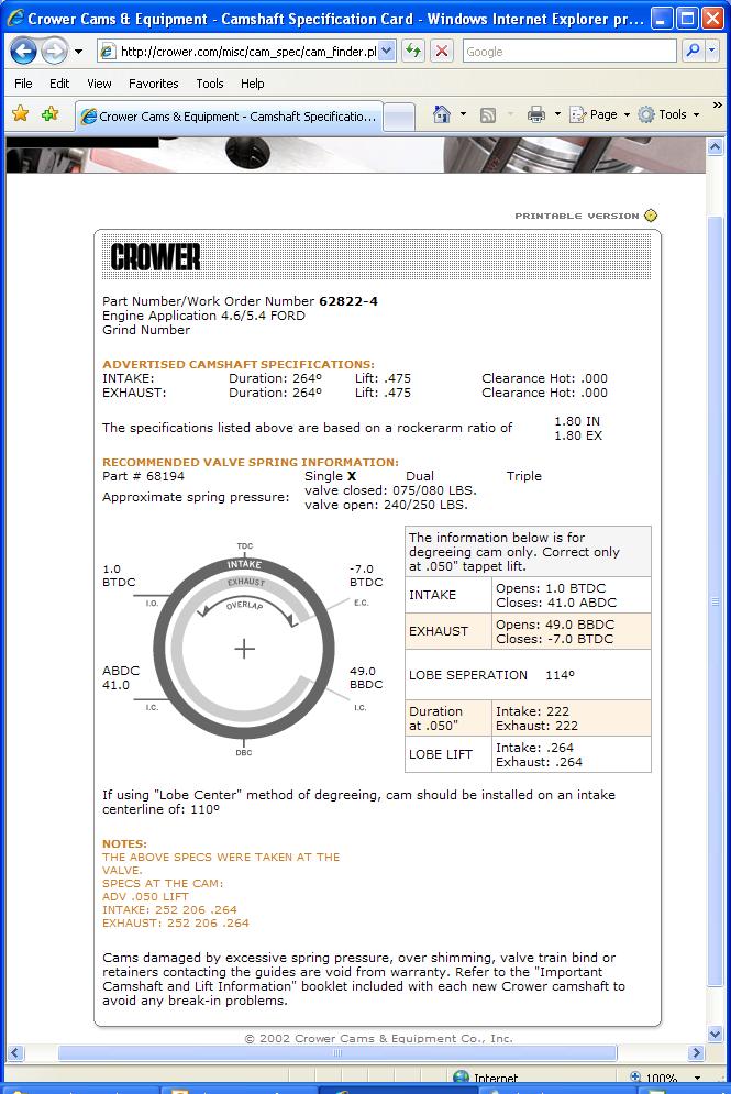
This information from Crower would be much more useful if in addition to lift at seat and 0.05" they would also publish lift at 0.20". Carl, why don't you blaze the trail here a bit and publish all three duration numbers: seat, 0.05", and 0.20"!
I picked this example, because it's actually relevant for boosted 928s. The modular Ford 4v engine is very simlar to 928 32v engine. We don't have anybody making cams specifically for boosted 928s, it's one size fits all. These Crower cams, like most boosted cams, seem to have about equal duration and lift between intake and exhaust. This makes sense, given the cylinder and port pressures.
This brings me to the earlier point about the bigger Webcam cams. Let's say I start with S3 cores that are modified to fit S4 heads. This gives me a lobe separation angle of 114 degrees. Then, let's say I'll get the 928MS 32vR3 intake cam (lift 0.442", duration 222 @ 0.05") and Webcam 279 exhaust cam (lift 0.442", duration 222 @ 0.05). Now, what I have is something that would probably work pretty well with a forced induction 5 liter street engine, since the stats match the Crower FI street cams for mod Ford except with slightly less duration.
Here's what Crower publishes on cams. These are forced induction street cams for mod Ford 4v. [EDIT: You can take home a full set of these billet cams for $1224.50... not priced for Porsche]:
This information from Crower would be much more useful if in addition to lift at seat and 0.05" they would also publish lift at 0.20". Carl, why don't you blaze the trail here a bit and publish all three duration numbers: seat, 0.05", and 0.20"!
I picked this example, because it's actually relevant for boosted 928s. The modular Ford 4v engine is very simlar to 928 32v engine. We don't have anybody making cams specifically for boosted 928s, it's one size fits all. These Crower cams, like most boosted cams, seem to have about equal duration and lift between intake and exhaust. This makes sense, given the cylinder and port pressures.
This brings me to the earlier point about the bigger Webcam cams. Let's say I start with S3 cores that are modified to fit S4 heads. This gives me a lobe separation angle of 114 degrees. Then, let's say I'll get the 928MS 32vR3 intake cam (lift 0.442", duration 222 @ 0.05") and Webcam 279 exhaust cam (lift 0.442", duration 222 @ 0.05). Now, what I have is something that would probably work pretty well with a forced induction 5 liter street engine, since the stats match the Crower FI street cams for mod Ford except with slightly less duration.
You are right, and I agree that having more dwell on the nose of the lobe is preferred. The reason why you will hardly ever find any manufacturer publishing much more than lift and duration info (IMHO) is that the profile is part of their proprietary solution. It seems that about half of the cam manufacturers don't even like to publish their lobe separation data. Of course, adding a little boost to the engine is another way to get more air through the opening with the cams you have available.
Last edited by ptuomov; 07-06-2009 at 07:13 PM.
07-06-2009, 06:32 PM
#94
By Tuomo
I don't probably have the time to answer this as well as I liked but I certainly don't agree, the reason is this, I have details of the latest Porsche engines including the MR6, the most directly comparable engines are the GT engines, that being GT3 and other engines based off it such as GT2 and GT1. They have the same valve inclination and basically the same stroke and in may cases the more important factor is the bore size.
The reason that is more important is because the valve inclination angle is the same the shrouding issues will be basically very very close. As such what size valves and cams are Porsche"s premier engine using? The GT3 road engine uses 41 mm and 34 mm and the latest GT3 engine (as of 2008) which is 3800 cc (increased bore like many strokers) has an increased bore around 103 mm and is the FIA GT3 spec engine although this may be out of date as things change quickly. It has 42 mm intakes with 35 mm exhausts. Where the street engine has lift of 12.7 mm the race engine has lift of 13.75 mm.
My own research of the 4V engine, which I must admit is a bit light on the ground, is that most likely 41 mm valve will be superior, these heads flow over 350 cfm at 0.500" or 12.7 mm Flow continues to rise if you had 13.75 mm lift. Personally as my experience shown improvements are possible and we may even achieve 400 cfm at that higher peak lift. Note on this head the CSA has not been increased but is around 2.6 sq" This head does outflow a Nascar Chevy 2.2 head upto its (Porsche's) peak lift but after 0.600" the Nascar head is superior.
My experience with 2V heads has produced gains from 215 cfm of a standard euro 2V head at 0.500" to the current 280 cfm at 0.500" with two more ports going to the flow bench today, they have a CSA of 2.15 sq" to 2.25 sq" I am trying to achieve 300 cfm and we are looking for air speeds (critical issue) around the 310 to 330 feet per minute mark.
Now just a little more info on this.
By Carl Fausett
Chevrolet Heads as used by NASCAR come in three (4) basic configurations, 23 Degree, 18 Degree SB2.2 and RO7 . All Four are aluminum. There are some aftermarket heads (such as Brodix and AirFlowResearch) that are different and are not used by NASCAR Teams because they are not allowed by NASCAR Rules. In general the actual heads used are superior to the aftermarket heads. I'll stop there.
Now on the lift issue, something I have looked at with the 2V engine, 0.600" cams are possible in fact they were made in the mid ninties, I looked at the issue further and in fact upto 0.650" is probably possible as far as the cam is concerned but I haven't worked out whether the springs will be possible, to handle that much lift.
As to the 4V engine, I measured the valves of the GT3 engine (don't have that to hand now) and there is no reason I can see that the lift cannot be increased at least to this level, i.e 12.7 mm or 0.500"
Now unless your engine can demand the air that the heads are flowing you most likely will lose power, the reason is that the airspeed will be slow, thus you cylinder filling wont be as good as it could be. If this is the case you need to fill the ports. Unless I am mistaken I believe they run the airspeeds upto the 350 to 365 feet per second mark in good heads, work out what your feet per second is. Formula for my 2V heads at this point is 280 cfm x 2.4/310= 2.11 sq" so if I manage to get 300 cfm the speed will be around 330 feet per second.
In the F1 engines the air speeds are very fast and the ports are not that big, they are not that big in the Nascar or Pro Stock engines either relative to their power, they all have high cam lifts, F1 engine are around 16 mm and have very large valves in relation to the bore, Nascar Pro stock uses an intake valve from 52.5 to 53.5% of the bore and have intake lifts of 0.800 To 0.850" to 1" for Pro Stock. The only reason I can see that the software Tuomo is using is not saying to use bigger valves or higher lifts is that the heads are not flowing as well as they should. I better sign off, work to do.
Greg
I disagree with you a bit here. For a 5.0 liter engine with these stroke, bore, and rod measurements, even the all-out effort engines have valves that are basically the same size as stock S4 valves. Look at Subaru Sti EJ25 Cosworth "big valve" heads or Ford 5.0L "Cammer" engine. So the valves are big enough for a 5.0.
With the stock valves, the intake for example hits diminishing returns at slightly above .400" lift. So who cares about the max lift as long as the cam spends a lot of time above .400" valve lift? This may also be the reason why 928 Motorsport chose not to offer much higher lift cams.
With the stock valves, the intake for example hits diminishing returns at slightly above .400" lift. So who cares about the max lift as long as the cam spends a lot of time above .400" valve lift? This may also be the reason why 928 Motorsport chose not to offer much higher lift cams.
The reason that is more important is because the valve inclination angle is the same the shrouding issues will be basically very very close. As such what size valves and cams are Porsche"s premier engine using? The GT3 road engine uses 41 mm and 34 mm and the latest GT3 engine (as of 2008) which is 3800 cc (increased bore like many strokers) has an increased bore around 103 mm and is the FIA GT3 spec engine although this may be out of date as things change quickly. It has 42 mm intakes with 35 mm exhausts. Where the street engine has lift of 12.7 mm the race engine has lift of 13.75 mm.
My own research of the 4V engine, which I must admit is a bit light on the ground, is that most likely 41 mm valve will be superior, these heads flow over 350 cfm at 0.500" or 12.7 mm Flow continues to rise if you had 13.75 mm lift. Personally as my experience shown improvements are possible and we may even achieve 400 cfm at that higher peak lift. Note on this head the CSA has not been increased but is around 2.6 sq" This head does outflow a Nascar Chevy 2.2 head upto its (Porsche's) peak lift but after 0.600" the Nascar head is superior.
My experience with 2V heads has produced gains from 215 cfm of a standard euro 2V head at 0.500" to the current 280 cfm at 0.500" with two more ports going to the flow bench today, they have a CSA of 2.15 sq" to 2.25 sq" I am trying to achieve 300 cfm and we are looking for air speeds (critical issue) around the 310 to 330 feet per minute mark.
Now just a little more info on this.
By Carl Fausett
We already know that, with a little bit of work, the heads will out-flow a Brodix NASCAR engine at lower valve lift levels. See this:
http://forums.rennlist.com/rennforum...rovements.html
http://forums.rennlist.com/rennforum...rovements.html
Now on the lift issue, something I have looked at with the 2V engine, 0.600" cams are possible in fact they were made in the mid ninties, I looked at the issue further and in fact upto 0.650" is probably possible as far as the cam is concerned but I haven't worked out whether the springs will be possible, to handle that much lift.
As to the 4V engine, I measured the valves of the GT3 engine (don't have that to hand now) and there is no reason I can see that the lift cannot be increased at least to this level, i.e 12.7 mm or 0.500"
Now unless your engine can demand the air that the heads are flowing you most likely will lose power, the reason is that the airspeed will be slow, thus you cylinder filling wont be as good as it could be. If this is the case you need to fill the ports. Unless I am mistaken I believe they run the airspeeds upto the 350 to 365 feet per second mark in good heads, work out what your feet per second is. Formula for my 2V heads at this point is 280 cfm x 2.4/310= 2.11 sq" so if I manage to get 300 cfm the speed will be around 330 feet per second.
In the F1 engines the air speeds are very fast and the ports are not that big, they are not that big in the Nascar or Pro Stock engines either relative to their power, they all have high cam lifts, F1 engine are around 16 mm and have very large valves in relation to the bore, Nascar Pro stock uses an intake valve from 52.5 to 53.5% of the bore and have intake lifts of 0.800 To 0.850" to 1" for Pro Stock. The only reason I can see that the software Tuomo is using is not saying to use bigger valves or higher lifts is that the heads are not flowing as well as they should. I better sign off, work to do.
Greg
07-06-2009, 06:42 PM
#95
Nordschleife Master
Bigger valves generally help in simulations, provided that I can run the imaginary engine at an arbitrarily high rpm. No surprise there, without rpm limit the maximum hp potential of an NA engine is mainly determined by the aggregate valve area. It's a bummer that we have that damn rev limit in real world. :-(
07-10-2009, 09:07 AM
#96
Here's some flow figures for the Chevy SB2.2 heads that were run in Nascar, they do some pretty big numbers, the two columns represent 2 years of development time, i.e No 2 was developed in 2007 and No 1 in 2005, it would be interesting to see what the RO7 heads could do!
ACFM
Lift No. 1 No. 2
-------- ------- -------
0.2000 131.9 142.9
0.3000 214.4 220.7
0.4000 298.8 306.7
0.5000 368.3 371.1
0.6000 409.8 408.5
0.7000 424.9 426.4
0.8000 441.6 446.4
0.9000 449.2 453.5
1.0000 451.2 459.2
I also can clarify why the good engine builders aim for 310 feet per second through the port, this figure of 310 is taken at 28 inches of water and when the engine runs it is actually double this figure which is then 0.55 Mach, so really what everybody needs to do is flow their heads if they are not stock, work out the csa and see where they stand.
Unfortunately my heads didn't get flowed today which is disapointing. If I can achieve 295 cfm to 300 cfm at 0.500" that will get me to this figure. You need to check you csa properly and the way to do this is with a mould.

Greg
ACFM
Lift No. 1 No. 2
-------- ------- -------
0.2000 131.9 142.9
0.3000 214.4 220.7
0.4000 298.8 306.7
0.5000 368.3 371.1
0.6000 409.8 408.5
0.7000 424.9 426.4
0.8000 441.6 446.4
0.9000 449.2 453.5
1.0000 451.2 459.2
I also can clarify why the good engine builders aim for 310 feet per second through the port, this figure of 310 is taken at 28 inches of water and when the engine runs it is actually double this figure which is then 0.55 Mach, so really what everybody needs to do is flow their heads if they are not stock, work out the csa and see where they stand.
Unfortunately my heads didn't get flowed today which is disapointing. If I can achieve 295 cfm to 300 cfm at 0.500" that will get me to this figure. You need to check you csa properly and the way to do this is with a mould.
Greg
07-10-2009, 09:37 AM
#97
Nordschleife Master
I also can clarify why the good engine builders aim for 310 feet per second through the port, this figure of 310 is taken at 28 inches of water and when the engine runs it is actually double this figure which is then 0.55 Mach, so really what everybody needs to do is flow their heads if they are not stock, work out the csa and see where they stand. Greg