When you click on links to various merchants on this site and make a purchase, this can result in this site earning a commission. Affiliate programs and affiliations include, but are not limited to, the eBay Partner Network.
Another possible method of making these connectors could be to scan one with a 3D scanner, then print them off on a 3D printer. The printers at least are getting steadily cheaper and better, though not sure if they can fully replicate the connector terminal channels.
There are a lot of parts for many different vintage cars that could be made and sold using this method. Simple-to-make (with a printer), but expensive-to-buy (in the present market) NLA Marelli switch ***** come to mind. I bet there are many more NLA Porsche, Bosch and other manufacturer parts that would be good candidates for this budding cottage industry.
Originally Posted by Jim bailey - 928 International
I personaly am happy that it is still available new because the cars will not run without it. Which reminds me I should buy one and tuck it away in my personal stash along side the new printed circuit foil that I bought for the very brown 1980....
Jim thats the best insurance you can have that you will never need either one...!
Another possible method of making these connectors could be to scan one with a 3D scanner, then print them off on a 3D printer. The printers at least are getting steadily cheaper and better, though not sure if they can fully replicate the connector terminal channels.
There are a lot of parts for many different vintage cars that could be made and sold using this method. Simple-to-make (with a printer), but expensive-to-buy (in the present market) NLA Marelli switch ***** come to mind. I bet there are many more NLA Porsche, Bosch and other manufacturer parts that would be good candidates for this budding cottage industry.
Cheaper printer use ABS, which can be OK for a lot of parts, but not for high temp uses. Also the cheaper printers are not really high resolution. Still, I've been wondering the same thing -- it seems like it could work for some parts -- particularly if someone wanted to do a little hand finishing. Maybe not the first choice, but in a situation where there's no viable alternative, it might be worth a try.
The trick is getting a good model.
I have easy access to a Makerbot Replicator 2x if we want to experiment with making a couple of parts.
One other thing to consider: part designs are usually protected IP. And while a manufacturer is likely to look the other way on very small volume enthusiast uses, the more it looks like a real business the more likely one is to get a firmly written WTF letter from counsel.
Actually Errka, I know I could design and print either an ABS or Nylon replacement end that would stand up well right now.
But I'm far too busy with the printer right now to consider it.
Actually Kevin the cheaper printers use PLA, which is much lower temp than ABS.
Of course nylon is really the best overall.
Indeed. I believe the 2X is currently the only Makerbot that can use either PLA or ABS (and you have to set platform temp accordingly). And the 2X is currently the most expensive of the cheaper printers. My point is even ABS is not really heat resistant -- though a bit better than PLA.
Nylon is definitely better.
Last edited by kevinr; 02-16-2014 at 10:48 PM.
Reason: Clarification
All the things I've been printing, I've made in solid works.
ABS has been the hardest to work with. There have been lifting troubles with it, mostly as I haven't wanted to make an ABS slurry. The nylon is showing to be pretty easy/good actually.
Get a small plastic box like 50mm L X 75mm W X 35mm H. You can use paper but you will need a release agent or a wax coating on the inside.
Get eight very thin sewing needles (or equivalent) 50mm or longer.
Take two of the needles and push them through both sides of the box about 8mm off the bottom of the box, centered in the box and separated by 15mm.
Take your connector and place it centered the needles.
Take two more needles and push them through the box perpendicular to the other needles tight over the top of the connector.
Repeat the procedure with the remaining four needles so you have a grid like # on top and bottom of the connector.
Take your silicone parts I & II and mix enough to fill the box to the top.
Pour the mix around the connector.
Wait the full recommended time for cure and then 30 minutes more.
Remove the needles.
Carefully remove the rubber mold from the box.
Take a new razor blade and cut the mold the long way (wire to spade connector end) through the center tracing the connector. Use a straightedge to ensure a clean cut. Do this on three sides, the top, bottom and the spade connector ends.
No carefully open the mold and extract the connector. Voila! You now have a mold to make your connector
Get four needles as those in the MOLD MAKING procedure.
Take the wire you have chosen and crimp the subminiature female spade connectors (available here ) onto the wire pair. (by the way 944 harnesses have a lot of "green wire" for various sensors so get a bad harness and you now have a source of many feet of this wire)
Place the wire in the mold and push two needles through the mold and into the spade connectors. Make sure the connectors are suspended and centered in the spade cavity. If you are not careful to do this the connectors will be poking out of you plastic pour. Don't worry if you have to do it a couple of times, its rubber.
Take two more needles and suspend the wire pair in its cavity. You may need two more needles if the wire will not stay in place laterally.
Take two thin pieces of wood or MDF (fiber board) and put gentle pressure to hold the mold together and prevent too much expansion
Mix the resin trying not to whip it as to reduce bubbles
Pour the resin into the mold
Wait the recommended set time plus 15 minutes
Remove the pins
Remove the casting from the mold
Clean up flashing with razor knife ( you may need to do some dremel work)
Total cost $66 and now you can make more for all your 928 buddies
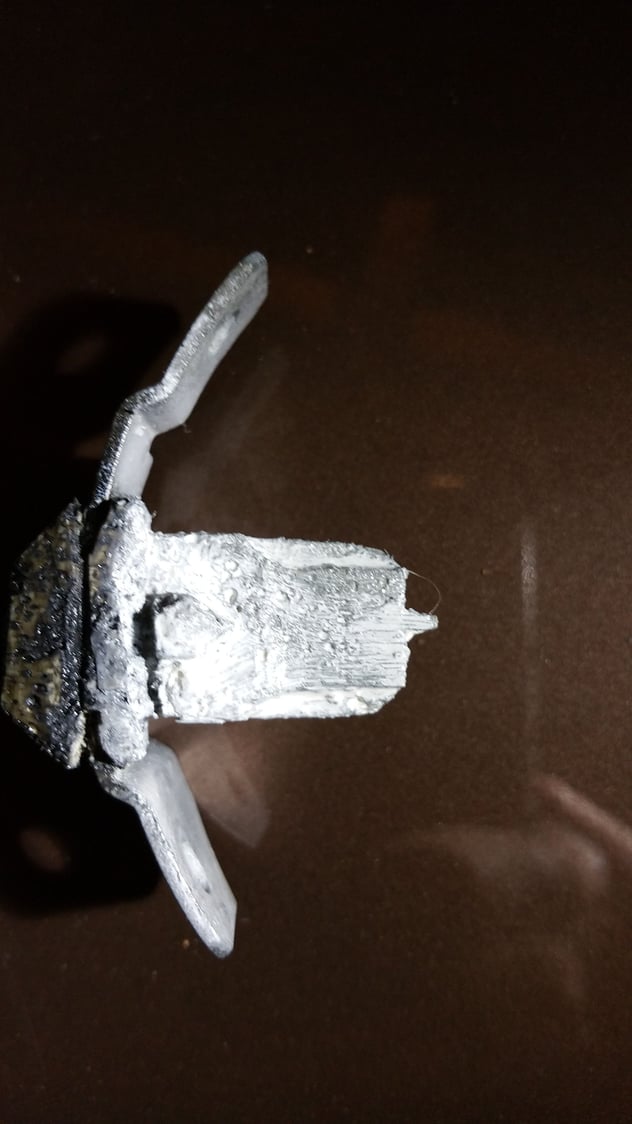
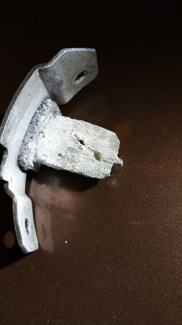
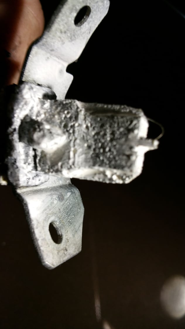
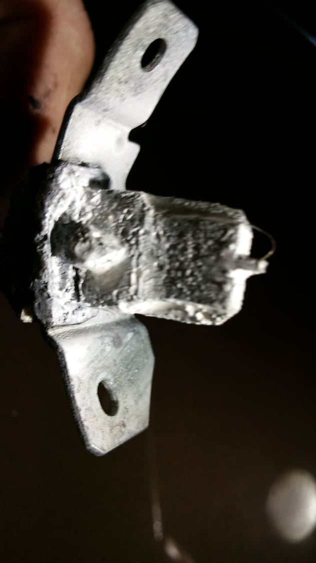
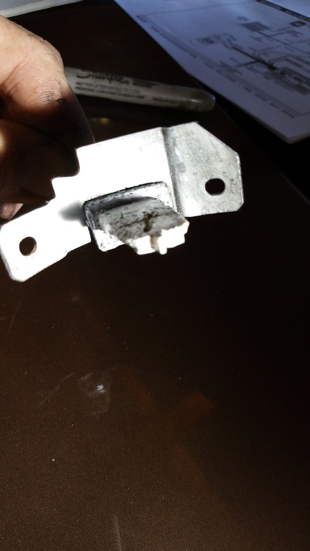
Here is a crude example I whipped up in 60 minutes start to finish. I used low density polystyrene and silicon putty. Both are inadequate for detail molds requiring strength, temperature resistance and non-porous.
Fronkenstein
Last edited by Fronkenstein; 07-19-2015 at 08:32 PM.
Reason: Add pictures
Old thread, but the title speaks to my question... which is...
If the green part of the green wire is coaxial, what about the wire connection from the ECU to the green wire? Is it a simple 2 conductor or is it something special?

 02-16-2014, 04:24 AM