
where does this vacuum line go?
 03-25-2008, 12:58 PM
#16
Rennlist Member
it's out of the WSM, but I had pulled it up awhile ago and saved it as a pdf, so I can't remember exactly where I got it.
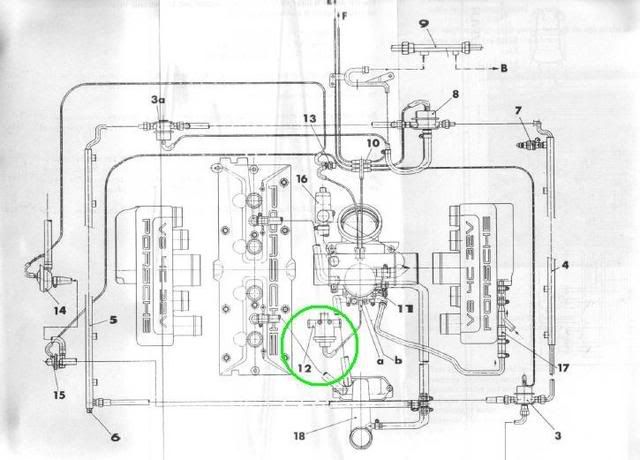
The copy I have at home lists what all the numbered parts are, and I want to just verify that I am giving you the correct info as to which of those regulators is in fact the egr - #12 (I think it is, becuase the TB hook-up point is emissions related) or #15 - there are so many damn regulators in the front of that engine! Mine is mounted on the cross brace. I'll double check tonite for you...
The copy I have at home lists what all the numbered parts are, and I want to just verify that I am giving you the correct info as to which of those regulators is in fact the egr - #12 (I think it is, becuase the TB hook-up point is emissions related) or #15 - there are so many damn regulators in the front of that engine! Mine is mounted on the cross brace. I'll double check tonite for you...

 03-25-2008, 03:23 PM
#18
Sharkaholic
Lifetime Rennlist
Member
Lifetime Rennlist
Member
Get a mity-vac vacuum tester. Plug it into the mysterious vacuum line and see if it holds a vacuum. If it does then cap it with a screw or something that holds a good seal. Pull the vacuum line from the damper next to it and check that for vacuum to see if the system holds. You might check a few others as well, if the system holds vacuum then just leave it plugged. It shouldn't be there and the only way to really be sure it wasn't slated to go somewhere else is to do an intake R&R. And chase down all the vacuum lines against the drawing already posted.
03-25-2008, 04:32 PM
#19
Racer
Thread Starter

Join Date: Sep 2006
Location: Simpsonville, SC
Posts: 298
Likes: 0
Received 0 Likes
on
0 Posts
Shane, good idea. In fact, I went out earlier and cranked the car and put my finger over it. The vacuum tried to pull my finger in; same with the damper.
It has been that way for at least a year with seemingly no ill affects. An intake R&R is in my immediate future...
I'm too worn out from my water manifold and MM projects to start this soon.
It has been that way for at least a year with seemingly no ill affects. An intake R&R is in my immediate future...
I'm too worn out from my water manifold and MM projects to start this soon.
03-25-2008, 09:20 PM
#20
Rennlist Member
Chris - diagram with references to the numbered and lettered components is on page 24-208 of the WSM....happy hunting!~
04-27-2008, 03:50 PM
#22
Racer
Thread Starter
Join Date: Sep 2006
Location: Simpsonville, SC
Posts: 298
Likes: 0
Received 0 Likes
on
0 Posts
Okay, I finally had some time to dig in today.
Is #12 the thing that sits between two hoses beside the coolant expansion tank, with one hose coming from the smog pump and the other going to the bottom of the air cleaner box? If it is, I have seen it referred to as the airpump change-over valve, diverter valve, and blow off valve.
The vacuum line should connect it to the front of the throttle body, correct?
Last edited by ckabee1; 04-27-2008 at 05:42 PM.
 [/IMG]
04-27-2008, 06:21 PM
[/IMG]
04-27-2008, 06:21 PM
#24
Rennlist Member
Okay, I finally had some time to dig in today.
Is #12 the thing that sits between two hoses beside the coolant expansion tank, with one hose coming from the smog pump and the other going to the bottom of the air cleaner box? If it is, I have seen it referred to as the airpump change-over valve, diverter valve, and blow off valve.
The vacuum line should connect it to the front of the throttle body, correct?
Is #12 the thing that sits between two hoses beside the coolant expansion tank, with one hose coming from the smog pump and the other going to the bottom of the air cleaner box? If it is, I have seen it referred to as the airpump change-over valve, diverter valve, and blow off valve.
The vacuum line should connect it to the front of the throttle body, correct?
04-27-2008, 06:29 PM
#25
Racer
Thread Starter
Join Date: Sep 2006
Location: Simpsonville, SC
Posts: 298
Likes: 0
Received 0 Likes
on
0 Posts
Yea, the diagram is VERY difficult to read, plus the reference for each has a different name for the part.
Man, those vacuum connections were a mess. #15 was connected to #12, the fantom line was unconnected at one end and connected at the splitter at the other, the elbow at the front of the throttle body was not connected to anything. Guess I wasn't the only one confused.
However, she ran fine.
Thanks for your help. On to the leaky expansion valve..,
05-24-2008, 09:05 PM
#27
Racer
Thread Starter
Join Date: Sep 2006
Location: Simpsonville, SC
Posts: 298
Likes: 0
Received 0 Likes
on
0 Posts
I don't have a picture and my wife has the camera, but my description above should direct you to the right place. It's not where you would think it would be based on the diagram.