When you click on links to various merchants on this site and make a purchase, this can result in this site earning a commission. Affiliate programs and affiliations include, but are not limited to, the eBay Partner Network.
To follow up on assembling the PP/ release bearing, having survived the process, I have a few pointers for clutch re-installation. This is actually straightforward, but there are a few obvious things that aren�t obvious until you actually do it.
Nota Bene- This seems to have worked on my �90, I may have done something wrong, but it hasn�t grenaded yet. Dunno whether there are any specific gotchas for other S4 model years. YMMV.
For the real mechanics here, if anything I wrote is incorrect, PLEASE chime in!
Pointers:
1. Once the PP/arm/release bearing is all together, get under the car and look at the flywheel, note where the locator pins are, 1 big one and 2 small ones. I rotated the engine by hand so that the big pin was straight down at 6 o�clock. I then made a mark with a marker on the edge of the PP in line with the big pin so I could lift the assembly into the bellhousing with the mark at 6 o�clock.
2. I did not need to drive any locator pins in or out of the PP during either disassembly or reassembly. This may not be the case for other years, or I�m just a moron and got lucky.
3. Leave the shims in the assembled PP/clutch assembly. When you start tightening the PP-to-flywheel bolts (step 15), the shims will fall out one by one.
4. Install the nylon release arm cup onto the ball on the bellhousing. I sprayed a small amount of lithium grease in there, and it still took a surprising amount of force with a prybar to get it to seat on the ball.
5. Assemble the PP, guide tube, intermediate shaft, and friction plate. I tracked down some Optimoly HT (now called Montagepaste, P/N 000 043 004 00 at the local Porsche dealer). It is like LM508 Copper antiseize but is much stickier. There are five things to lubricate:
1. Intermediate shaft sliding surfaces where the clutch disc sits.
2. Ball cup bushing on arm - lithium grease
3. Contact point between throwout bearing and arm- Montagepaste
4. Rear splined end of the intermediate shaft - the part that slides into the clamp sleeve to the torque tube- Montagepaste.
5. A little dab on the end of slave clutch cylinder piston. Basically any parts with metal to metal contact that a) need to come apart again or b) slide, slip or pivot. (Thanks to Dave C for this list!)
6. According to a TSB I found the GTS guide tube gets no grease of any kind (bolded at the bottom), there are several posts that mention this but I'd not seen the TSB posted:
7. Slide the torque tube coupler onto the torque tube shaft back into the torque tube to get it out of the way. Slide the guide tube all the way forward into the release bearing. To get the clutch pack up into the bellhousing, the rear of the intermediate shaft has to be positioned within the release bearing so that it is JUST forward of the flanges to which the guide tube mounts.
8. I had the car up on 6 ton jackstands, so the bottom of the bellhousing was about 18-20� off the ground. I tried to use a jack on which to rest the clutch assembly, but then the jack was in the way. SO- With a pair of 3 ton stands and a 3 foot length of 2x3, I built a 15� high �crossmember� that sat just under the bellhousing, so that I could rest the clutch pack on it when it was part way up into the housing.
Check out this high tech drawing:
9. Have one of the PP bolts nearby. Flat on your back, piece of plywood on your chest for protection, pick up the clutch pack, make sure the mark is at 6 o�clock, and that the relase arm is pointing straight up. Heft the assembly into the bellhousing. It needs to be STRAIGHT up and down so that the friction plate slides up and in in front, and the intermediate shaft fits in back. Move the 2x3 into position on the 3 ton stands and you can rest the assembly there. Rest your arms.
10. Lift the assembly up into the bellhousing, the goal is to A) get the big locator pin on the PP into the hole in the flywheel, and B) get the intermediate shaft into the pilot bearing. I think I only got part A done, and then I put in one of the nine PP bolts. They�re long enough to engage 2-3 turns of thread.
11. You can reach through the �windows� in the PP to to jiggle the friction plate around to get it so you can insert the intermediate shaft into the pilot bearing. Once it is in, you�re golden.
12. With the PP shimmed, you ought to be able to rotate the rear end of the intermediate shaft and watch the friction disc turn.
13. Rotate the motor and install the remaining PP bolts in crisscross fashion. I put them all in finger tight but didn't torque them down yet.
14. At this stage, the PP is still shimmed, and the release arm can be slid around relative to the release bearing. From below, maneuver the relase arm so that it is sitting partially on/over the ball cup bushing. Once everything is re-assembled (including the bellhousing cover, clutch slave and pushrod), the arm is seated on the nylon bushing by pushing the clutch pedal to the floor.
15. Start torquing the PP bolts down in crisscross pattern, turning the motor by hand. The shims fall out during this step.
16. Pull back the guide tube and bolt it to the flanges in the bellhousing. These were a little hard to start but once the first was in, the second was easier ('cause the intermediate shaft was then aligned?) The final product looks like this:
17. Move the coupler into place and rotate the motor so that you can see up the bolt holes in the coupler. The intermediate shaft needs to be positioned in the forward-aft axis so that both coupler bolts will line up with the grooves in the intermediate shaft (forward) and the TT driveshaft (rearwards) Then the bolts can be installed and torqued down.
18. Button up bellhousing, reinstall starter, clutch slave, pushrod, etc. I left the rear pair of bellhousing bolts out for future misadventures without having to drop the exahust. I didn't need to bleed the clutch.
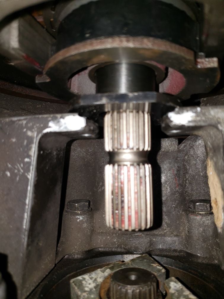
Here's a picture of what a properly inserted intermediate shaft looks like.
In this picture the shaft is probably 6 mm too far forward, but you get the idea.
Our (Kevin W. and I) future steps will also also include inserting the allen bolt into the coupler groove closest to the clutch first and then use a pry bar to push the coupler with intermediate shaft attached into alignment with the groove on the driveshaft.
This is an old thread so i will add some new info for others that might read it here.
I have posted these stub shaft alignment instructions in other threads I just cant find it so i will write it out here.
The clutch pack stub shaft should be positioned back about 3 to 4 mm from bottoming out in the pilot bearing,
this will put the bearing boss of the shaft in the center of the bearing and give the drive shaft some freedom to move,
To do this take the stub shaft and the guide tube and install them.
NOTE without the clutch pack in the way you can clearly see then depth of the stub shaft in the pilot bearing
NOTE the pilot bearing should be installed so its flush with the end of the crank.
Once the parts are in place then slide the coupler onto the stub shaft .
NOTE you will also need to verify that the Rear pinch bolt at the transaxle input clamp is inspected ,
so that the drive shaft is centered and the bolt is properly tightened to 66 ft/lbs and use a drop of blue loctite.
NOTE always inspect the drive shaft cutouts at all 3 of the pinch bolt locations ,
and always make sure the bell housing is fastened to the engine before inspecting the cutouts ,
or the measurements will be off.
NOTE if the drive shaft is out of position then use the front clamp with the bolt tightened,
then press the shaft into the correct position,
a helper is a good thing , so you can see as the shafts moves into the cutout,
the drive shaft will move with a prybar.
After the rear pinch bolt is installed then slide the front coupler onto the stub shaft and fit the clamp bolts,
slide the the stub into position 3 to 4MM back from bottoming out ,then snug down the clamping bolts .
Once this is done then use a marking pen to put a line on the stub shaft at the back of the guide tube .
This will be your reference point to line the stub into the correct position.
Remove the mock up parts and then install the complete clutch pack.
NOTE as an option instead of driving the line up pins out of the flywheel, this banging force is transferred to the thrust bearing not good.
Instead loosen all 4 of the engine bell housing bolts so they are about 3 threads left,
then remove the two bolts that hold the trans mounts to the rear cross member.
Now the whole TT assembly will slide rearwards,
this will let the clutch pack drop out without any pin driving.
NOTE the bell housing must be drawn together after dropping the clutch pack to facilitate the stub shaft mock up instructions.
Once the mock up is complete loosen the two lower bolts and slide the TT assembly back to install the clutch pack.
NOTE always fit a new release arm bushing,
you can use a dremel to grind open the bushing lip so it will be easier to press onto the ball.
NOTE make sure your release arm and guide tube and TOB are all a matching set,
the latest is the GTS version mixing these parts will cause release issues in the future
I am in the early stages of a clutch replacement on my '87 S4, have read the WSM, all threads that I could find on the subject, etc. I thought I was prepared to tackle this one, but have been proven wrong. I need some A&C from the collective:
Right now the car is on the lift, the old pressure plate is loose, and the whole assembly is trapped in place by the release lever on the ball. It will not come out. I figured I should wash the black soot from my face, neck and arms to come inside and ask for help before I figured out how to cut the lever with my plasma cutter. That will get it out, but it might set the car on fire.
How I got here:
Followed the WSM and related posts by moving starter, removing slave cyl, removing lower cover, sliding coupler back, sliding guide tube forward.
Step 9 on page 30-6b of the WSM says : "disengage release lever from ball joint by pressing lever down toward flywheel"
-That wasn't happening. The wording didn't make sense either. The lever could not be positioned in any way that would allow it to come off of the ball. I figured that if I got the PP loose, I could shift things backward to allow the lever to release from the ball.
I fabricated the 3 shims from step 10, but there was no way they would fit in the clutch. there was not enough clearance. This clutch is worn down to nothing, I assumed that was why there was no clearance.
I decided not to drive the centering pins back(step 11). I read above that this may not be necessary.
I removed the pressure plate screws and the assembly came loose from the flywheel. It rained black clutch soot everywhere and will not come off of the ball.
If anyone has any suggestions, I am all ears. Right now all I can think of is: cut the ball, or cut the release lever. I probably have over 20 things in my shop that end with the word "saw".
OK take a deep breath
put the PP bolts back into the flywheel and snug them down .
Take a long lever and pry the release arm to the back of the car this will release the clutch.
put a dab of contact cement on one of the spacers for the clutch and put it into place, turn the crank and fit the other two.
Now the release arm will come off the ball bushing with the PP bolts still installed.
Now whats not in the WSM I suggest to loosen the bell housing bolts till they are about 3 turns from coming out , 4 bolts total.
Then remove the two bolts that hold the trans mounts to the rear cross member.
Now you will be able to slide the front bell housing and the trans axle rearwards and they will slide on the 4 bolts,
this will give you room to remove the clutch assembly.
NOTE you will have to rejoin the bell housing to the block to do the stub shaft mock up prior to fitting the clutch assembly.
You can do this with the two lower bell housing bolts to draw the parts together.
this so you get an accurate measurement of the guide tube to stub shaft.
Once the mockup is done then slide the trans axle back again
Thanks for your quick response! I hadn't considered manually flexing the PP to get the shims in, and shifting the bell housing. This site and the people on it have been a valuable resource over the last 4 years to get this car running correctly - and it will continue to be.
I will give this a shot after work today. I knew I needed to step away last night. When you are frustrated and own 20+ saws, every problem needs cutting.
Did you try to put the shims in before unbolting the Pressure Plate pack from the flywheel?
Once you unbolt it, the springs push everything back and the rivets 'go flush'.
Note: When putting it back together, the lowest shim will fall out when you tighten down the bolts. Make sure you wear eye protection (BTDT).
Did you try to pop the arm off the bushing before unbolting stuff?
It's easier that way.
As Stan noted, slide a long screwdriver or smallish pry bar up from below and just push the top of the arm towards the back of the car. The arm should pop off the ball without a whole lot of effort.
If you have to pry hard, something's wrong.
Joe,
It is definitely wrong. There was no gap to install any shims in before I loosened any screws, and the arm would not come off of the ball with any amount of prying. That is how I ended up removing the PP screws - hoping that that would allow the arm to slide off of the ball. I'm sure if I could rewind back a few days knowing what I know now I could find a way to get the arm off of the ball, but I need to move forward.
Moving the bell housing back would give me an inch or so of clearance, but the two upper bolt heads are harder to get to than the ball. I bent a 19mm wrench so that I could get on them, but due to the bend in the wrench, it will not stay on the bolt head when I apply torque.
Reinstalling the PP back on the flywheel was equally as difficult. After fiddling with it for an hour and getting covered once again with what I hope is non-asbestos clutch dust, I got one screw in and the whole assembly is locked up I don't know why, but it is.
After laying under the car with a fairly clear mind and weighing my options, I believe that a clean surgical strike on the ball is the best option. I think I can limit the collateral damage and the PP should just fall out. A new ball is $40. I could fiddle with reinstalling the PP for another few days, or spend an equivalent amount of time working on the two upper bolts to the bell housing, but I think this route is the best chance of success.
The question now is: If there is a deformed ball shaft remaining, how hard will it be to get on it and unscrew it? I think I read that it is loctited in, so I will need to heat it before removal.


 01-22-2008, 03:10 AM


 https://rennlist.com/forums/928-forum/256378-metal-to-metal-scratching-noise-after-clutch-job-now-with-video.html