

Roger and I have an exciter wire question
 11-17-2007, 01:42 PM
#31
Rennlist Member
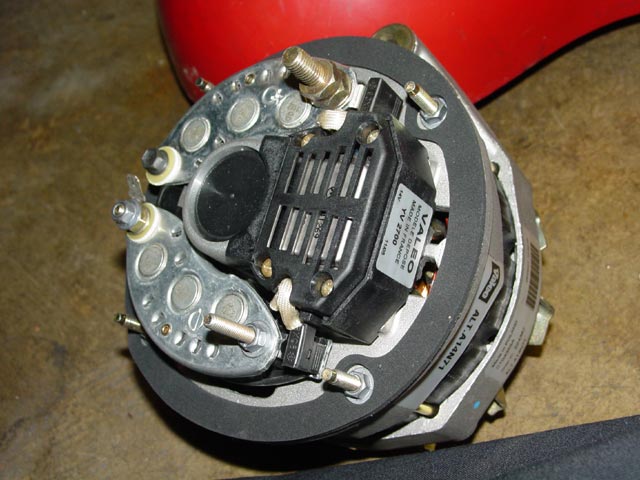
I'm a bit concerned about that last pic. I think that plate should be at case ground. More info here, below is a pic from that page showing proper hookup of the exciter wire. The second pic shows how the exciter wire terminal is insulated from that plate -- in that second pic, the long stud on that plate closest to the camera is case ground. BTW, you are putting the correct shroud and duct on there, right?
I just realized -- you do not have the case grounded to the car. So, in the last pic, it is grounding through the voltmeter. Connect one end of a jumper cable to the alternator case, the other end to the engine block or other good ground and try again. Your voltage when repeating the last measurement should be 0v. Connect the exciter wire to the exciter wire terminal. It should be 0v key off, 8-10v with key on.

I just realized -- you do not have the case grounded to the car. So, in the last pic, it is grounding through the voltmeter. Connect one end of a jumper cable to the alternator case, the other end to the engine block or other good ground and try again. Your voltage when repeating the last measurement should be 0v. Connect the exciter wire to the exciter wire terminal. It should be 0v key off, 8-10v with key on.
 11-17-2007, 01:49 PM
#32
Basic Sponsor
Rennlist
Site Sponsor
Rennlist
Site Sponsor
This is the same alternator used for 77 to 84 cars 928 603 114 01. Up to 82 had to have the modified shroud and gasket as well as a charge resistor. But not the 83 & 84 cars.
Maybe its a bad alternator - possible.
I will ship Tim another one on Monday.
Maybe its a bad alternator - possible.
I will ship Tim another one on Monday.
__________________

Does it have the "Do It Yourself" manual transmission, or the superior "Fully Equipped by Porsche" Automatic Transmission? George Layton March 2014
928 Owners are ".....a secret sect of quietly assured Porsche pragmatists who in near anonymity appreciate the prodigious, easy going prowess of the 928."
Does it have the "Do It Yourself" manual transmission, or the superior "Fully Equipped by Porsche" Automatic Transmission?
George Layton March 2014928 Owners are ".....a secret sect of quietly assured Porsche pragmatists who in near anonymity appreciate the prodigious, easy going prowess of the 928."
11-17-2007, 02:00 PM
#34
Rennlist Member
Rog, as far as I'm concerned the exciter is behaving properly and the last test is invalid. See my above post. What started you down this path? Was the alternator not charging when installed?
11-17-2007, 02:26 PM
#35
Basic Sponsor
Rennlist
Site Sponsor
Rennlist
Site Sponsor
Hi Dave,
Tim may need to add the detail.
The car was not charging with the original alt. Tim does not remember seeing a charge light on the dash.
New alt. and similar problems.
Jim suggested the wiring harness may be toast (hope not).
I am happy to throw another new alt. at it as long as we know thats the problem.
I am shipping one anyway to be safe.
Roger
11-17-2007, 04:14 PM
#36
Chronic Tool Dropper
Lifetime Rennlist
Member
Lifetime Rennlist
Member

The photos show the voltage testing on the plastic milk crate. You need to add a ground strap from the alternator case to frame/engine to make any of the voltage readings valid. OK to use a jumper cable just for the testing. I now understand the measurement 12.6V from alternator frame to ground. 
11-17-2007, 06:21 PM
#37
Addict
Rennlist Member
Artist Formerly Known As 84totheFloor
Rennlist Member
Artist Formerly Known As 84totheFloor
Thread Starter
The photos show the voltage testing on the plastic milk crate. You need to add a ground strap from the alternator case to frame/engine to make any of the voltage readings valid. OK to use a jumper cable just for the testing. I now understand the measurement 12.6V from alternator frame to ground.
Bob, thanks so much. Indeed the alternator unit was not grounded as a whole atop the milk crate. I've run a jumper cable to the housing of the alternator and a ground point and now get the following...
1. Alternator housing to ground with key IN or OUT - 0V.
2. Detached exciter wire to ground - key out - 0V
3. Main terminal to ground - key out - 12.3V
4. Detached exciter wire to ground - key in - 10.9V
5. Main terminal to ground - key in- 11.9V
6. Voltage differential of about 1V between main terminal and exciter wire with key in.
The dash is behaving the same - put key in and the bulb check flashes quickly and then goes away. After 2 seconds, the central warning light and low oil pressure light start flashing.
Gauge light The bulb for the alternator gauge light is soldered into a small circuit board within the voltage/oil pressure area. I have tried to check continuity through that circuit and have always gotten indication that there is indeed continuity. So too, in holding up the small bulb to white light, it appears that the filament is intact. But since it does not light up during the bulb check, I'm still curious.
Last edited by 85fortheDrive; 11-17-2007 at 07:28 PM.
11-17-2007, 07:28 PM
#38
Electron Wrangler
Lifetime Rennlist
Member
Lifetime Rennlist
Member
The exciter wire should not be at almost battery voltage with the car not running... that it tests OK without the alternator connected suggests the alternator is driving this high - it should not untill it is spinning.
Alan
Alan
11-17-2007, 08:10 PM
#39
Chronic Tool Dropper
Lifetime Rennlist
Member
Lifetime Rennlist
Member
Get the reading from exciter teminal to ground just for grins (not sensitive to key position, then reconnect the exciter wire and grab key-in and key-out readings. The exciter terminal should be at zero volts to ground with the alternator not alternating. It should also be at zero with the wire connected and the key off. The voltage there with key on but not spinning will need to come from someone who's tested this on a 928. Once the engine is running and the alternator is making correct voltage, the exciter terminal should be at close to battery voltage. It will be only very slightly less with the bulb and resistor on one side of the terminal, and a diode in series with the regulator circuitry on the other side.
11-17-2007, 09:20 PM
#40
Three Wheelin'
I've been intently following this web with the same problem and the additional problem of having no voltage showing on the voltmeter. I have the full set of 6 workshop manuals for the early cars but can't find anything directly related to the charging system. So I have been hawking on this web every chance I get for updates. Somewhere in this web it was suggested to test voltage across the two nuts that hold the gauge in place. I find out that one of my nuts is way too loose and not making contact with the circuit board. I tighten the nut, bingo the gauge now works but still no exciter bulb. I test all the bulbs within the gauge and they all work but when I shine a light into the holes that should illuminate the exciter bulb I can't seem to find the correct position. Another post informs me the bulb is under the gauge. I remove the gauge and then find the correct bulb. I run 12 volts to the bulb and it does light but only when I use the end of the wire where it is soldered. It wont illuminate at the end of the circuit board where it is powered. I resolder this joint and the bulb now lights from where it gets its power. I replace the pod and now I have a working gauge, exciter bulb and a functional charging system. This forum is absolutely incredible. It just amazes me how efficent and powerful this site is. Thank you one and all.
11-18-2007, 04:13 PM
#41
Addict
Rennlist Member
Artist Formerly Known As 84totheFloor
Rennlist Member
Artist Formerly Known As 84totheFloor
Thread Starter
1. Gauge light works. Tested it with 12V. Resistor was not plugged into circuit board during this test. (Pic)
2. As to Bob's suggestion, I have the instrument cluster pulled at the moment, so I can't do checks to the exciter wire. I did check the exciter terminal and found that there was 0.25V to ground - key out.
More to come.
What an interesting process.
BTW - I'm delighted that FBIII was able to find a solution based on this !
11-18-2007, 06:36 PM
#42
Addict
Rennlist Member
Artist Formerly Known As 84totheFloor
Rennlist Member
Artist Formerly Known As 84totheFloor
Thread Starter
Thanks to HUGE help from Dave McKenzie, I've done some work trying to determine the integrity of the electrical system from the instrument panel down to the alternator.
Here's what I've done:
1. The printed circuit board seems okay with respect to the alternator gauge circuit. (See pic)
2. The 4th pin in the 14-pin connector socket is linked to the exciter wire. I tested this and there is continuity between this pin in the female socket and the end of the exciter wire.
3. The 12th pin is turned on when the key is turned in the ignition.
So it seems that the electronics between the instrument panel and the exciter wire are okay.
Remember, the inconsistencies with the alternator have not been present at a cold start. It has been after the car has been running or has been shut off and then turned back on that the alternator voltage has dropped to below 12V.
N.B. The wiring diagrams in the WSM were somewhat helpful, but if you're testing this, know that the pin configurations are probably different than an 84,
11-19-2007, 01:03 AM
#43
Addict
Rennlist Member
Artist Formerly Known As 84totheFloor
Rennlist Member
Artist Formerly Known As 84totheFloor
Thread Starter
I cleaned all of the 14-pin points on the printed circuit board and checked all of the gauges. Then I did something  really dumb. I reinstalled the fuel/temp gauge and the voltage/oil pressure gauge in the reverse positions. (They are completely symmetrical from behind).
Stupidly, I did not check the positions of them until after I plugged all three of the 14 pin harnesses in and turned the key for an ignition check.
SMOKE!!!
Yep, a small portion of the PCB insulation got cooked a little. It is not too bad, but there are small areas of the circuitry foil that are now exposed. I checked continuity between the ends of the foil circuits that overheated and they seem fine. In fact, when I returned the instrument panel to the car and connected it, it behaved just like before, with the central warning light and oil pressure light blinking after two seconds at ignition.
Suggestions for reinsulating the copper foil circuit board lines?
The 1984 model circuit boards are no longer in production. If it is wiser to do so, I will look for a used replacement.

really dumb. I reinstalled the fuel/temp gauge and the voltage/oil pressure gauge in the reverse positions. (They are completely symmetrical from behind).Stupidly, I did not check the positions of them until after I plugged all three of the 14 pin harnesses in and turned the key for an ignition check.
SMOKE!!!
Yep, a small portion of the PCB insulation got cooked a little. It is not too bad, but there are small areas of the circuitry foil that are now exposed. I checked continuity between the ends of the foil circuits that overheated and they seem fine. In fact, when I returned the instrument panel to the car and connected it, it behaved just like before, with the central warning light and oil pressure light blinking after two seconds at ignition.
Suggestions for reinsulating the copper foil circuit board lines?
The 1984 model circuit boards are no longer in production. If it is wiser to do so, I will look for a used replacement.
11-19-2007, 03:51 AM
#44
Electron Wrangler
Lifetime Rennlist
Member
Lifetime Rennlist
Member
I wouldn't worry too much - I'd think clear nail polish would be an option - anyone know if it has anything nasty in it?
Boy this simple alternator swap is turning out to be anything but...
I still think the alternator/regulator has a problem from what you have tested so far.
Did you ever try starting the car without the alternator - or at least truning the oignigtio on and seeing what the dash does? (you do need to connect together the 2 big terminals that would normally go to the alternator big terminal).
You should be abe to start and run the car his way for a short while - just on the battery. Does everything work right then?
Alan
11-19-2007, 11:39 AM
#45
Addict
Rennlist Member
Artist Formerly Known As 84totheFloor
Rennlist Member
Artist Formerly Known As 84totheFloor
Thread Starter
I still think the alternator/regulator has a problem from what you have tested so far.
Did you ever try starting the car without the alternator - or at least truning the oignigtio on and seeing what the dash does? (you do need to connect together the 2 big terminals that would normally go to the alternator big terminal).
You should be abe to start and run the car this way for a short while - just on the battery. Does everything work right then?
My response