Notices
928 Forum 1978-1995
Sponsored by:
Sponsored by: 928 Specialists

vacuum diagram

Thread Tools
 
Search this Thread
 
Old 08-26-2009, 12:10 AM
  #16  
83sweet928
Advanced
 
83sweet928's Avatar
 
Join Date: Aug 2009
Location: Nashville, TN
Posts: 99
Likes: 0
Received 0 Likes on 0 Posts
Default

Thanks for the reply, if you lean over the passenger side and reach in just left and down from the back of the TB down a bit you will feel them. I Will try to get a picture tomorrow.
Old 08-26-2009, 12:19 AM
  #17  
Landseer
Rennlist Member
 
Landseer's Avatar
 
Join Date: Sep 2007
Location: Johnson City, TN
Posts: 12,143
Received 356 Likes on 205 Posts
Default

Is it shown in either of these two pictures???
Attached Images   
Old 08-26-2009, 12:29 AM
  #18  
Landseer
Rennlist Member
 
Landseer's Avatar
 
Join Date: Sep 2007
Location: Johnson City, TN
Posts: 12,143
Received 356 Likes on 205 Posts
Default

Gio,

For diagrams (or equivalent descriptions in this case + troubleshooting ), try the Moorehouse CD set, CD1 section 2.15, "service info by year".

Try the 1987 year, starting on page 34. That should get you going. 88 and 89 will give info also, but the way these documents work is that the first year of a particular change gets the heavy documentation.

Also try Dwaynes intake write-up for the 87.


I'm using the hell out of this set of documents for the 85 model year for other reasons.
Old 08-26-2009, 12:34 AM
  #19  
83sweet928
Advanced
 
83sweet928's Avatar
 
Join Date: Aug 2009
Location: Nashville, TN
Posts: 99
Likes: 0
Received 0 Likes on 0 Posts
Default

YES...the second picture is it.
Old 08-26-2009, 12:41 AM
  #20  
Landseer
Rennlist Member
 
Landseer's Avatar
 
Join Date: Sep 2007
Location: Johnson City, TN
Posts: 12,143
Received 356 Likes on 205 Posts
Default

Ahh, the 'themostatic valve in liquid cooling system', in the diagram. One side to control valve I, One side to vac source.

The shape of the control valve I and II in the diagram are exaggerations of the shape of the valves on the car, kind of anatomically correct in terms of shape and location of the various vac ports on them, so you should be able to trace stuff now???

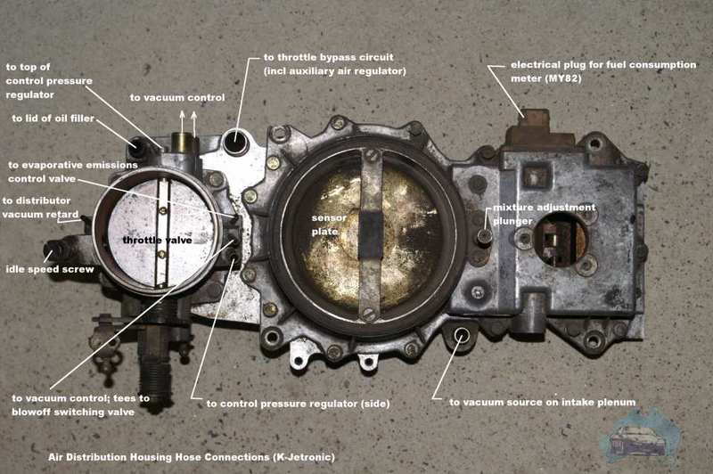
The vac sources 1 and 2 on the TB are confusing though from the picture.

I'm running the distrbutor timing advance ( and one side of the thermostatic valve) from the port on the back of the TB that is closer to the passenger side. Am running fuel regulators off the one on the drivers side back of TB. Seems to be working ok.
Attached Images  
Old 08-26-2009, 12:45 AM
  #21  
83sweet928
Advanced
 
83sweet928's Avatar
 
Join Date: Aug 2009
Location: Nashville, TN
Posts: 99
Likes: 0
Received 0 Likes on 0 Posts
Default

Does this give vacuum or take vacuum?
Old 08-26-2009, 12:47 AM
  #22  
83sweet928
Advanced
 
83sweet928's Avatar
 
Join Date: Aug 2009
Location: Nashville, TN
Posts: 99
Likes: 0
Received 0 Likes on 0 Posts
Default

In the diagram it is showin the location at the front of then motor, isnt this near the rear just behind the TB?
Old 08-26-2009, 12:51 AM
  #23  
Landseer
Rennlist Member
 
Landseer's Avatar
 
Join Date: Sep 2007
Location: Johnson City, TN
Posts: 12,143
Received 356 Likes on 205 Posts
Default

I think its the only way it can go. That part looks out-of-place in the diagram from a space perspective, probably due to crowding of the diagram.

What else could it be?

Its working for me.

Same with the ports 1 and 2 on the TB. Shown in wrong orientation I think.

Maybe send Wally Plumley a PM with a link to this thread and your other one for some real pro-help.
Old 08-26-2009, 01:02 AM
  #24  
danglerb
Nordschleife Master
 
danglerb's Avatar
 
Join Date: Oct 2006
Location: Orange, Cal
Posts: 8,575
Received 3 Likes on 3 Posts
Default

1 on the that diagram is I think called "ported" vacuum, atm at idle, and goes to manifold vacuum as soon as the throttle plate opens a bit, and goes to thermo valve and dist.

2 is always manifold vacuum and goes to fuel regulators, etc.
Old 08-26-2009, 01:04 AM
  #25  
Landseer
Rennlist Member
 
Landseer's Avatar
 
Join Date: Sep 2007
Location: Johnson City, TN
Posts: 12,143
Received 356 Likes on 205 Posts
Default

Thanks, Mike!
Old 05-06-2017, 11:45 AM
  #26  
mikegnx
6th Gear
 
mikegnx's Avatar
 
Join Date: Feb 2017
Posts: 6
Likes: 0
Received 0 Likes on 0 Posts
Question Vacuum line images

I bought a 1982 Porsche 928, the vacuum hoses were not in the right place, on my throttle body I have 2 small vacuum inlets in the front and 2 in the back, most images I found have 1 in the front and 2 in the back. Does anybody have an image that shows where the 4 vacuum inlets go to?
Old 05-06-2017, 12:08 PM
  #27  
Daniel5691
Drifting
 
Daniel5691's Avatar
 
Join Date: Jun 2014
Posts: 3,126
Received 235 Likes on 140 Posts
Default

this?
Old 05-20-2018, 08:09 PM
  #28  
Mrmerlin
Team Owner
 
Mrmerlin's Avatar
 
Join Date: May 2004
Location: Philly PA
Posts: 27,891
Received 2,251 Likes on 1,245 Posts
Default

On that picture where would the vacuum advance port come from ?
It shows the port for vacuum retard next to the idle adjustment screw.

I have a 78 5 speed with a single port advance unit.,
and am getting conflicting diagrams,
the port on the front of the TB has vacuum at idle .


Quick Reply: vacuum diagram


All times are GMT -3. The time now is 09:58 PM.