
Exhaust pics lightweight 3'' system

 12-14-2013, 07:04 AM
#32
Addict
Rennlist Member
Rennlist Member
Thread Starter
No those valves are from a 944 model, they only came out in one year, I think that was 1989. I have been told they are expensive and hard to get. I did some research years ago when I was looking to do this job and I found a 49 mm 911 valve that seemed close and was available back around 2007, 2008 on Pelican Parts for about $20. that may be worth investigating, they were made in Switzerland for memory.
12-14-2013, 07:08 AM
#33
Addict
Rennlist Member
Rennlist Member
Thread Starter
Hilton that is interesting, I have been paying rental for years, how much was your bottle to buy? Who fills it and what do they charge? I just got an argon and it was about $160 for a D. Yes you are right pure argon, it is also good for aluminium in the mig.
12-14-2013, 11:31 AM
#34
Rennlist Member
Join Date: Feb 2011
Location: Mostly in my workshop located in Sweden.
Posts: 2,230
Received 463 Likes
on
248 Posts
�ke
12-14-2013, 04:26 PM
#35
Nordschleife Master
I notice from their site they've got more stockists now too so it looks like word is getting out (I heard about them on the local aussie welding forum. List of locations/retail stockists here: http://speedgas.com.au/argon.html.
edit: A new fill of their Argo-shield (93/5/2 AR/CO/O) is around $130 last time I phoned Martin (the guy at Speedgas HQ in Manly Vale).
Last edited by Hilton; 12-14-2013 at 05:47 PM.
12-15-2013, 05:47 PM
#36

slate blue: (quote)
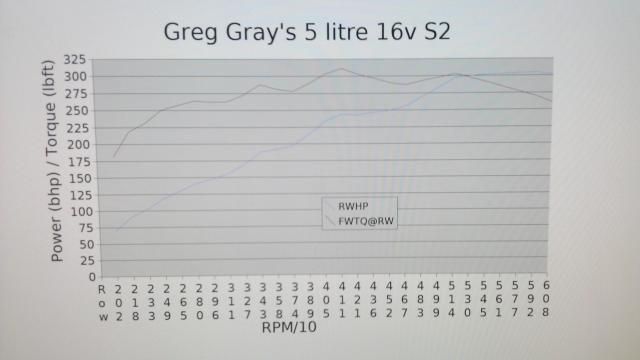
The thing is this engine runs out of puff once it reaches 5000 rpm, it makes over 300 rwhp at that speed. I recently went back to look at the head flow numbers and with the cams it has I suspect peak flow is around 220 cfm. This gives a max potential HP of approx 450 HP. To convert my rwhp numbers back to flywheel numbers we end up just under 400, I would be relaxed about 390 HP. (When it was a 4.7 L it made around 350 HP.)
A cheap and easy experiment would be to retard the valve timing by a degree or so. This will move the hp peak higher. My suzuki airplane engine also runs out of steam at 5300 and I may try the same on it.
12-16-2013, 01:44 AM
#37
Addict
Rennlist Member
Rennlist Member
Thread Starter
Well I indeed did try this and it absolutely killed the power, I suspect two things, one the cams have a very wide LSA and retarding them means they open even later. They are also then missing out on maximum scavenge from the exhaust if we do this. This is probably the greatest power killer of all. The car did pick up power when the cams were advanced but the idle was poor. With the new engine management coming and the MAF being deleted this may allow the cams to be advanced and couple this with bigger better flowing valves it will show what this engine can do. It'll certainly be more than 400 HP but by how much? I don't want to lose what is the best part of this engine which is the torque. I will try and post a dyno graph later that my friend did for me to show the current situation. The main problem is really why bother as I don't want the engine long term and selling them for anything close to what they are worth is pretty difficult.
 12-17-2013, 04:36 AM
#39
Addict
Rennlist Member
Rennlist Member
Thread Starter
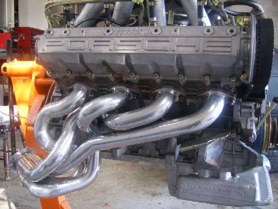
Ok I was asked about the header pipes and where they run and the angle they sit under the car.
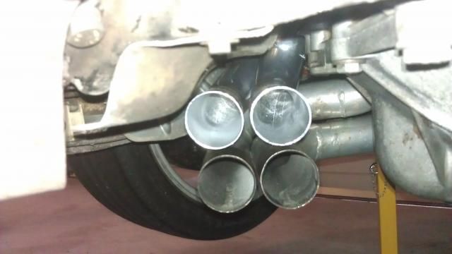
So you can see the pipes run to the edge of the heat shield, I kept as much clearance from the bellhousing as possible. You can see there is quite a lot of room to those bellhousing bolts and the housing can be accessed easiliy. I may have given the person that PMed a bum steer as this design may also work in LHD format. I will try to get a pic where the LHD column would be positioned. It may need to be tweaked but looks doable. The question remains when the larger 2" stepped system is made, where to position the tri-y collectors?
So you can see the pipes run to the edge of the heat shield, I kept as much clearance from the bellhousing as possible. You can see there is quite a lot of room to those bellhousing bolts and the housing can be accessed easiliy. I may have given the person that PMed a bum steer as this design may also work in LHD format. I will try to get a pic where the LHD column would be positioned. It may need to be tweaked but looks doable. The question remains when the larger 2" stepped system is made, where to position the tri-y collectors?
12-17-2013, 05:21 PM
#40
Addict
Rennlist Member
Rennlist Member
Thread Starter
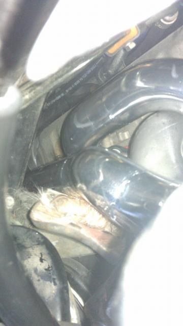
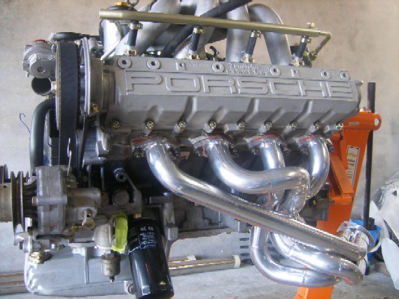
O.K that gives all an idea of what sort of clearance you may have with this design for a LHD vehicle. Ignore the battery cable, as this wouldn't normally be in the way
05-28-2016, 03:39 AM
#41
Addict
Rennlist Member
Rennlist Member
Thread Starter
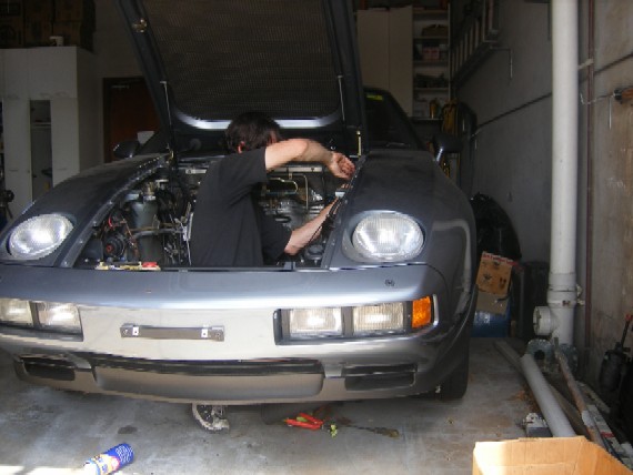
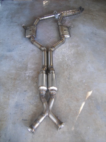
Guys here are a few pics of my exhaust, it has taken forever to build, forever is 3 months full time BTW. The reason it took so long was multiple, but I did build almost everything myself, bar the Burns mufflers and collectors. Also all the welds in the system after the headers were ground internally, very very time comsuming. All welds were back purged too, this makes a huge difference, without this I would say it is pointless to try and build a really good system. Also working on the ground slows you down along with the fact, 3'' is very hard to fit to a S2 while maintaining excellent ground clearance.
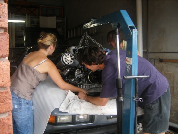
My car with one man power.
My girly assistant.
The headers after coating
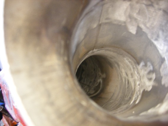
This photos shows what I did with welds internally, it has all been smoothed out.
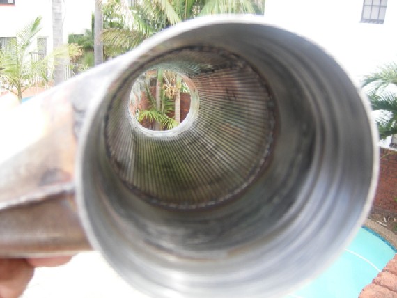
This is a gutted GT muffler, it has been fitted with 3'' pipe that I made like the Burn's units are, the perforated core is a fine lightweight mesh, these mufflers weigh 2.5 kgs each. The Burns units weigh 1 kg each.
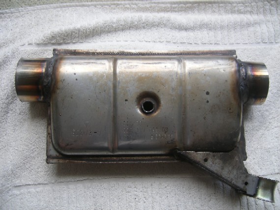
I also packed the mufflers with some new fibreglass and wrapped the perforated core with the stainless wool, you do this to protect the fibreglass from the heat.
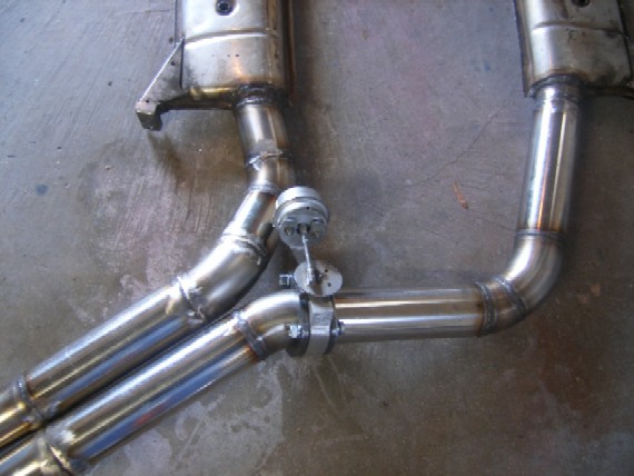
My home made X-Pipe
The variable backpressure valve
The whole system including the headers weighs 30 kgs, if I didn't try to save weight a 3'' system would have ended up weighing a portly 65 kgs.
What does it sound like, well in 2 weeks I will know. I suspious that it will be too loud, time will tell.
My car with one man power.
My girly assistant.
The headers after coating
This photos shows what I did with welds internally, it has all been smoothed out.
This is a gutted GT muffler, it has been fitted with 3'' pipe that I made like the Burn's units are, the perforated core is a fine lightweight mesh, these mufflers weigh 2.5 kgs each. The Burns units weigh 1 kg each.
I also packed the mufflers with some new fibreglass and wrapped the perforated core with the stainless wool, you do this to protect the fibreglass from the heat.
My home made X-Pipe
The variable backpressure valve
The whole system including the headers weighs 30 kgs, if I didn't try to save weight a 3'' system would have ended up weighing a portly 65 kgs.
What does it sound like, well in 2 weeks I will know. I suspious that it will be too loud, time will tell.

Comparison


Close up
Back in 2006 it was my first experience using a TIG which in fact I borrowed. The welds are solid though which is good, so I am happy about that.