When you click on links to various merchants on this site and make a purchase, this can result in this site earning a commission. Affiliate programs and affiliations include, but are not limited to, the eBay Partner Network.
Dave - not that I know of - but its the brains of the whole cooling fan/flap system - the final stage is just the motor drivers and fan failure adaptation. All the control logic is in the controller that monitors all the sensors and system state. These include water temp, intake over-temp, torque converter oil temp and AC high pressure. This module is powered by Battery (30) (NB unfused) and also Ignition (15) (fused - usually via X-Bus), it also monitors hood open/close status and AC on/off status. After ignition off the system stays active for the 'Fan After Running' mode: Fans run after shutdown if the intake is very hot (=> whole engine is very hot) until the intake temp is sufficiently cooled (via Intake Temp Switch). This function employs a timer after the ignition is turned off. I'm not certain of the timer length - but functionally even 5 minutes should be plenty adequate to cool the engine. In many locations this would never be triggered. In Phoenix in summer-time its a daily thing - but even here I don't think my fans have ever After Run for more than 2 minutes max - usually 20-30 seconds - just as well for the battery. Note the fans will only After Run if the hood is closed (to keep your digits intact)
In my experience these controllers are pretty reliable (they live a pretty easy life) - so likely used replacements are also very viable for long term use and likely quite plentiful from a supply/demand basis
Alan
No news �^ there. I have 10 of these units on my bench and every single one fails to �turn off� after 30+ minutes. There is a common age-induced flaw in either the control units or �87+ 928s.
Yes, they all run the fans as appropriate. But they all draw 80-90 mA continuously in standby with all �off conditions� satisfied. There are at least 4 board revisions in these without a part number change.
Hence why I asked if there�s more documentation than what�s in the WSM as that would inform my further testing.
The failure mode noted above here (just a longer delay) is not really noticeable unless you are testing for it. But as you say 90mA continually is slightly excessive - still for most regularly driven cars it would still be pretty much an under the radar thing. Once we are talking about a rarely driven car its gets to be a pain.
I've never taken a controller apart to look at it but the usual method is a relay to power the device from (30) initiated by (15) but maintained on for a delay by a dedicated timer or microprocessor - e.g. the later window controller. So it could be the relay stuck on - swapping it could be a plan. Newer designs would not use a relay for this - but it was a common method at that time.
A few additional observations on the above described current draw.
The process I followed for all these observations was the following:
Hatch switch disconnected so I could work with it open
Hood closed
Battery ground strap removed from body but connected to ground via alligator patch cable
Turn ignition on, then off
Open door and close it
Connect ammeter to strap and body and then disconnect patch ground cable so as to not interrupt the 'power on' state.
Interior lights come on and stay on for ~30 seconds (didn't clock it) current draw 2.72 Amps
Lights come off and draw is now ~105 mA
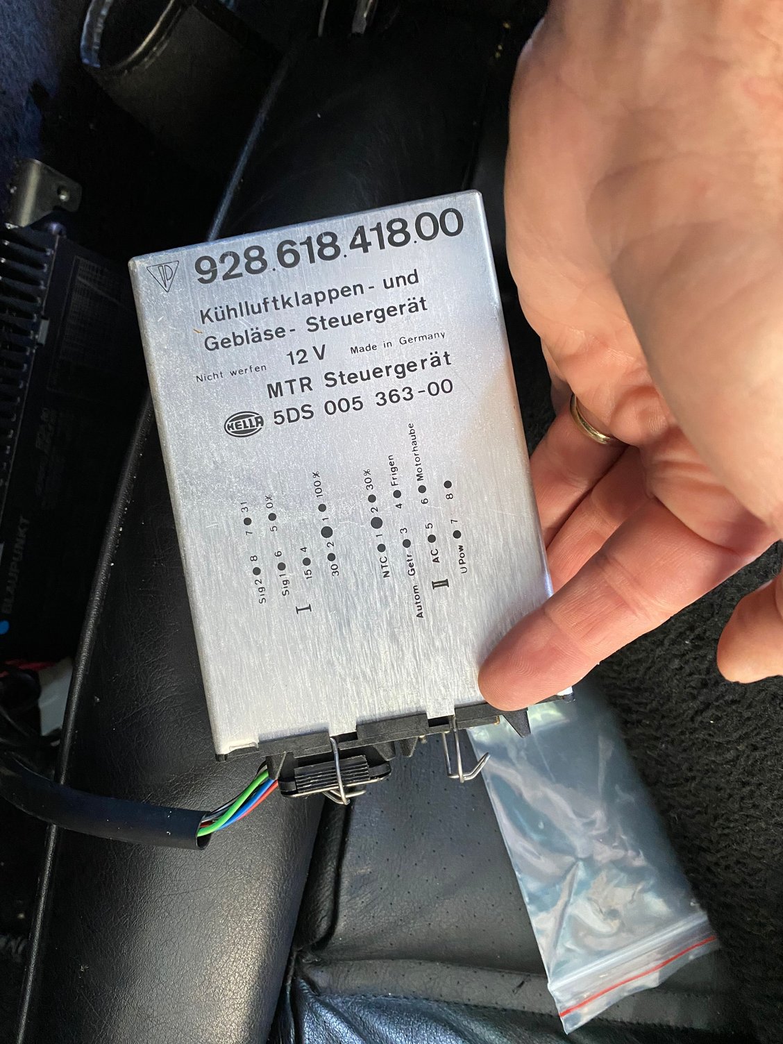
Access fan control module near passenger seat (without opening the door) and remove connector I (see pic below). Current draw is now ~13 mA.
Reconnect connector I and current draw stays at ~13 mA
If I conduct the above steps but instead of disconnecting connector I on the module disconnect connector II, the current drops but to 60mA. If I reconnect connector II, current goes back to 105mA.
This time I stayed in the garage tooling around while the module was in the temporary 105mA state. The time was less than hour to revert back to the 13mA draw. something between 50 and 55 minutes.
Luis,
Good test procedure! (and well written up). It seems for your case the timer (however that is implemented) does work but has a very long elapsing period - 10 times longer than you need probably.
Dave have you opened up a failed module to take a look at the implementation - can you share some pics? the only one I have is in my car and its 100F+ in the garage and will be for quite a while here.
This time I stayed in the garage tooling around while the module was in the temporary 105mA state. The time was less than hour to revert back to the 13mA draw. something between 50 and 55 minutes.
huh. I didn�t have the patience/notion to wait the long.
Originally Posted by Alan
Dave have you opened up a failed module to take a look at the implementation -
I have.
Originally Posted by Alan
- can you share some pics?
I don�t know. Depends upon how IB is �feeling� today about my account. I�ve had very limited functionality on Rennlist for over a year.
I am interested to see what is going on in one of the control modules as well.
My 928 is to early to have this module, from my understanding, but from experiences with other cars of this vintage, I would be expecting capacitors drifting in capacitance to be a large part of the time delay failure.
1/10 amp dropping to 1/100 in an hour, might even be working as designed.
No I don't think so. Functionally 5 minutes is enough - with the engine off and fan after-run on things cool down sufficiently quite quickly. If the timer is not accurate you might want to make that min period longer. But the max period has to be defined for something else - battery life. Its not the 100mA that you need to care about - its the 15-20A continual draw while the fans are in after-run. If the intake temp switch fails closed the timer is the only thing preventing the battery from being run down. In this case the fans will run for the timer length every single time you shutdown. Note that the ~105mA measured is 92mA for the fan controller dropping to 0mA when the controller turns off - the other 13mA was residual for everything else in the car.
Well the Rev 3 module is a bit of a mess but the Rev4 cleaned things up quite a bit - but seem to be basically the same - different layout (makes me wonder about revs 1 & 2 though!).
Both are 80C49 microcontroller modules. No obvious relay here so I think the power on-maintenance is likely via a transistor. The timer is almost certainly digitally implemented in the microcontroller. It looks like there is a multi-turn trim-pot - but I'd assume that's to set the water temperature trigger point in conjunction with the Op Amp in the top corner. If the control functions work OK - you'd think the timer would be fine too. Not so obvious what the issue might be.
Found notification of thread bump deep in my inbox. Epilogue:
I tested 9 different fan controllers. All went to a 5 mA (IIRC) standby draw after 55 to 65 minutes under “shop cold” conditions. (Bulk of variation most likely due to test procedure.)
IMO waiting a hour to go to standby when all inputs are “reading cold” from the first clock tick seems lazy.
So… nothing to see here…
… other than that you can’t do a final-final parasitic draw test in less than an hour.
So it seems pretty conclusive they designed for about an hour - which I think is stupidly long. 10 minutes is more then enough - even in Phoenix in 120F summers after a long hot run the fans never after-run for more than 2-3 minutes - there will be few places worse.
So it seems pretty conclusive they designed for about an hour - which I think is stupidly long. 10 minutes is more then enough - even in Phoenix in 120F summers after a long hot run the fans never after-run for more than 2-3 minutes - there will be few places worse.
It�s not even that �good.� It�s as if they thought that after 45 minutes the intake or ATF temp might go up and require the fan. Sure there�s heat bloom after shutoff, but after 10 minutes, if the senders haven�t triggered then they�re not going to.
The extra 20-ish bytes of code to run the fan until all senders were below threshold and then set a (5 minute) timer was just too much.

 06-25-2021, 01:38 PM