

Pass. Airbag sensor removed-can I test it?
 01-20-2006 | 10:14 PM
#1
Thread Starter
Rennlist Member
Joined: Aug 2002
Posts: 2,676
Likes: 236
From: Warrenton, VA
After some procrastinating & a 60+ degree day, I delved in to pulling the passenger a/b sensor out. Andrew, thanks for the helpful print-ready pages.
Ed, your earlier post commenting on the 'tear-off' nuts being a p.i.t.a. is right on. I got one off with vicegrips & some choice words, and I'm thinking that a 1/2" socket might get enough grip on the back nut to get it off (manual says 1/4" hex socket to put it back on....I don't see how that's possible)...anyway I'll try that tomorrow.
Does anybody know:
- Can the sensor be bench tested once it's out?
- Are there any contacts that should be checked/cleaned aside from the 3-prong plug at the end of the sensor pigtail?
- After I remove the sensor, can I reinstall the removed elect. components (LH/EZK, etc), hook up the battery & drive until I have a working sensor to put in at a later date?
01-20-2006 | 10:52 PM
#2
Addict
Rennlist Member
Rennlist Member
Joined: Jul 2001
Posts: 7,330
Likes: 110
From: Shawnee, KS, USA
Originally Posted by JPTL
I got one off with vicegrips & some choice words...
 (Putting it that way, it sounds like you made the right choice using Vicegrips, doesn't it?)
Originally Posted by JPTL
- Can the sensor be bench tested once it's out?
Originally Posted by JPTL
- Are there any contacts that should be checked/cleaned aside from the 3-prong plug at the end of the sensor pigtail?
).
Originally Posted by JPTL
- After I remove the sensor, can I reinstall the removed elect. components (LH/EZK, etc), hook up the battery & drive until I have a working sensor to put in at a later date?
It just seems so likely that your problem would be the same as mine and at least one other person I'm aware of (that is, just oxidation at the connector) that I'd try addressing that possibility first (Deoxit-ing the connecting pins) before messing with sensor removal/replacement unless you know that the sensor is failing.
Come to think of it, is anyone aware of a case where one of the crash sensors has actually failed? I've never heard of such a case.
01-21-2006 | 03:20 AM
#3
Shameful Thread Killer
Rennlist Member
Rennlist Member
Joined: Aug 2004
Posts: 19,831
Likes: 101
From: Rep of Texas, N NM, Rockies, SoCal
Originally Posted by JPTL
Does anybody know:
- Can the sensor be bench tested once it's out?
- Are there any contacts that should be checked/cleaned aside from the 3-prong plug at the end of the sensor pigtail?
- After I remove the sensor, can I reinstall the removed elect. components (LH/EZK, etc), hook up the battery & drive until I have a working sensor to put in at a later date?
Not really, the connector at the controller is prolly fine.
You can reinstall the LH/EZK and drive, you will have no airbag.
Most probable is the sensor has high resistance at the connector to the harness. Use some DE-ox-IT or a small amount of grease when reassembling and you should be fine. Note, that for the "airbag Malfunction" annunciator to go off, it must be reset with a Bosh Hammer tool, or on some cars, the Speake Spanner will work.
Doc
01-21-2006 | 02:20 PM
#4
Thread Starter
Rennlist Member
Joined: Aug 2002
Posts: 2,676
Likes: 236
From: Warrenton, VA
Thanks again for the replies/details. In doing a universal(covering all models) search for "airbag" on Rennlist, there are plenty of technical questions posted, and very few answers. Seems that the only answers with any kind of useful technical info. are on the 928 board (you guys in particular). Says something for the depth of knowledge amongst 928 owners (myself excluded).
Anyway, I've opted not to try to remove the back 'tear-off'. Using any kind of standard socket is a no-go (as you both probably already knew) since the tearoff is too close to the sensor to allow for the thickness of the socket wall. I'm going to rely on the odds & try a contact clean to see it that works.
Ed and/or Doc, you can probably help me out with one more thing here....
I can't seem to find any image/reference "D68-8 test point 7" in my wsm as referred to in Ed's post.
Ed/Doc, could you clarify?
When you say: "..you should see 10 kOhm between pins 1 and 2 and 0 to 0.5 Ohm between pins 2 and 3." which pins are you referring to?
I've labeled them as a, b, and c for the sensor connector pins, and d, e and f for the chassis connector pins.
01-21-2006 | 05:35 PM
#5
Addict
Rennlist Member
Rennlist Member
Joined: Jul 2001
Posts: 7,330
Likes: 110
From: Shawnee, KS, USA
Originally Posted by JPTL
Ed and/or Doc, you can probably help me out with one more thing here....
I can't seem to find any image/reference "D68-8 test point 7" in my wsm as referred to in Ed's post.
Ed/Doc, could you clarify?
When you say: "..you should see 10 kOhm between pins 1 and 2 and 0 to 0.5 Ohm between pins 2 and 3." which pins are you referring to?
I've labeled them as a, b, and c for the sensor connector pins, and d, e and f for the chassis connector pins.
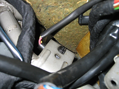
Now, as to which pins (a.k.a. terminals) are numbers 1, 2, and 3, I have to admit that I can't remember for sure, but I know I did this resistance test myself, so I must have known at one time. Get some really good lighting on the sensor connector (what you're calling a, b, and c), looking into the end, i.e., the way you took your photos. Are you sure you can't see some slightly raised identification of each terminal? I have faint memories of possibly seeing them identified that way. If your photo were perfectly focused and high res enough, I'd probably be able to see what I'm looking for.
Actually, now that I look at your photos again, I see some white-ish blobs close to your "d" and "e" labels. Are these possibly raised-print terminal identifiers?
01-21-2006 | 08:05 PM
#6
Thread Starter
Rennlist Member
Joined: Aug 2002
Posts: 2,676
Likes: 236
From: Warrenton, VA
Ed, thanks for checking into this. Before your most recent post, I checked the resistance at the pins that I guessed were 1 & 2, figuring that a ballpark resistance reading would confirm which pins were which.
I got a 10k reading at "a" & "b", and a .4+/- at "b" and "c". Since the readings were right on, I'm guessing that those pins are 1,2 and 3 respectively.
After a shot of contact cleaner on the pins as well as at the base of the sensor (manual saying that the metal must be 'bright'), reinstalled, powered up, started up, and the the light's on again. What's interesting is that the airbag icon (red idiot light) flashed off for a brief moment, then on again followed by the text readout "Airbag fault".
I don't recall it flashing off before. Maybe it's doing a check of the system, getting an a-ok, then pulling the old code from the PCM.
I guess it's HammerTime.
Thanks again for your help.
01-21-2006 | 08:20 PM
#7
Addict
Rennlist Member
Rennlist Member
Joined: Jul 2001
Posts: 7,330
Likes: 110
From: Shawnee, KS, USA
Originally Posted by JPTL
I guess it's HammerTime.
Seriously, get that fault reset with the Hammer and I'll bet you're home free. Reading out the fault code will be interesting, too. I'll bet it'll be a 3230 (right front sensor line resistance too high, fault no longer present). Or maybe a 3226 (right front sensor resistance to earth/ground too high).
Trending Topics
01-22-2006 | 03:21 AM
#8
Shameful Thread Killer
Rennlist Member
Rennlist Member
Joined: Aug 2004
Posts: 19,831
Likes: 101
From: Rep of Texas, N NM, Rockies, SoCal
Originally Posted by JPTL
Ed, thanks for checking into this. Before your most recent post, I checked the resistance at the pins that I guessed were 1 & 2, figuring that a ballpark resistance reading would confirm which pins were which.
I got a 10k reading at "a" & "b", and a .4+/- at "b" and "c". Since the readings were right on, I'm guessing that those pins are 1,2 and 3 respectively.
After a shot of contact cleaner on the pins as well as at the base of the sensor (manual saying that the metal must be 'bright'), reinstalled, powered up, started up, and the the light's on again. What's interesting is that the airbag icon (red idiot light) flashed off for a brief moment, then on again followed by the text readout "Airbag fault".
I don't recall it flashing off before. Maybe it's doing a check of the system, getting an a-ok, then pulling the old code from the PCM.
I guess it's HammerTime.
Thanks again for your help.
I got a 10k reading at "a" & "b", and a .4+/- at "b" and "c". Since the readings were right on, I'm guessing that those pins are 1,2 and 3 respectively.
After a shot of contact cleaner on the pins as well as at the base of the sensor (manual saying that the metal must be 'bright'), reinstalled, powered up, started up, and the the light's on again. What's interesting is that the airbag icon (red idiot light) flashed off for a brief moment, then on again followed by the text readout "Airbag fault".
I don't recall it flashing off before. Maybe it's doing a check of the system, getting an a-ok, then pulling the old code from the PCM.
I guess it's HammerTime.
Thanks again for your help.
The airbag startup test sets several faults on purpose, then resets them, then does a sensor check, then validates the sensor readings and determines the state of the airbag circuit. It is supposed to come on, then go off, then come on for about 2 seconds then go off as long as the key is on(and no circuit faults).
If you still have the 'airbag malfunction' it's a sign of one of two things. Either the previous error is still in the controller memory, and is a false reading, which will be cleared by a Hammer reset. Or, you still have a high resistance, and the fault is real, which will remain after a Hammer reset. Did you really read 10k ohms, or did you mistakenly see k ohms, but were atually reading 10 ohms? It's important, the circuit will never work with 10k ohms in the line.
I know what a hassle it is to reach, so if possible, leave the sensor in place, just diconnect the sensor cable again, and use your meter on it while laying on your back in the car. Hassle, but at least you don't have to pull the sensor again.
After that get,,,er, Hammered.
Doc
01-22-2006 | 12:08 PM
#9
Addict
Rennlist Member
Rennlist Member
Joined: Jul 2001
Posts: 7,330
Likes: 110
From: Shawnee, KS, USA
Originally Posted by docmirror
Well, I'm hoping you're mistaken in teh reading of "10k". the resistance should be 10 ohms. Set the ommeter to the lowest scale, usually 1k, but sometimes 100 ohms. The reading is now in ohms, not k-ohms.
Originally Posted by docmirror
The airbag startup test sets several faults on purpose, then resets them, then does a sensor check, then validates the sensor readings and determines the state of the airbag circuit. It is supposed to come on, then go off, then come on for about 2 seconds then go off as long as the key is on(and no circuit faults).
If you still have the 'airbag malfunction' it's a sign of one of two things. Either the previous error is still in the controller memory, and is a false reading, which will be cleared by a Hammer reset. Or, you still have a high resistance, and the fault is real, which will remain after a Hammer reset. Did you really read 10k ohms, or did you mistakenly see k ohms, but were atually reading 10 ohms? It's important, the circuit will never work with 10k ohms in the line.
If you still have the 'airbag malfunction' it's a sign of one of two things. Either the previous error is still in the controller memory, and is a false reading, which will be cleared by a Hammer reset. Or, you still have a high resistance, and the fault is real, which will remain after a Hammer reset. Did you really read 10k ohms, or did you mistakenly see k ohms, but were atually reading 10 ohms? It's important, the circuit will never work with 10k ohms in the line.
I still think that the WSM is correct in stating that terminal 1 to 2 resistance is supposed to be 10 kOhm.
01-22-2006 | 12:26 PM
#10
Addict
Rennlist Member
Rennlist Member
Joined: Jul 2001
Posts: 7,330
Likes: 110
From: Shawnee, KS, USA
J.P., IMHO, you're probably done. Hammer-reset your airbag controller, and see how it goes.
I'd like to provide a little more info, for the record, for future "finders of this thread". In case the terminals aren't actually identified in the connector, another way of figuring it out is to look at the wire colors. You should be able to see the inner wire insulation colors peeking out between where the cable jacket ends and where the connector starts (like in this photo, where you can clearly see at least the red and yellow wires from my left-front crash sensor connector)
I'm also attaching the part of the electrical schematics (in this case, for the '90, since that's what I already had scanned, but '91 should be the same) that contains airbag devices and wiring.
For both the left front and right front crash sensors, terminal "1" is the one that "goes the other way" on the connectors.
The left front terminal/wiring colors are as follows:
I'd like to provide a little more info, for the record, for future "finders of this thread". In case the terminals aren't actually identified in the connector, another way of figuring it out is to look at the wire colors. You should be able to see the inner wire insulation colors peeking out between where the cable jacket ends and where the connector starts (like in this photo, where you can clearly see at least the red and yellow wires from my left-front crash sensor connector)

I'm also attaching the part of the electrical schematics (in this case, for the '90, since that's what I already had scanned, but '91 should be the same) that contains airbag devices and wiring.
For both the left front and right front crash sensors, terminal "1" is the one that "goes the other way" on the connectors.
The left front terminal/wiring colors are as follows:
- Terminal 1: YE/WT
- Terminal 2: WT
- Terminal 3: RE/WT
- Terminal 1: YE
- Terminal 2: WT/RE
- Terminal 3: RE/BK
01-22-2006 | 08:39 PM
#11
Thread Starter
Rennlist Member
Joined: Aug 2002
Posts: 2,676
Likes: 236
From: Warrenton, VA
Okay, now I'm confused.
If I recall correctly, I got a 10.0 reading with the (digital) meter's dial set at "20k ohms" at pins "a" and "b" in my diagram. My second reading was between "b" and "c", and that reading was .4. Admittedly in my comfort of the resistance numbers agreeing with the tolerances, I likely confused the pin configuration. Also, I didn't focus on whether the 4 was in the tenths, hundredths, or thousandths place. I just liked that 4 to 5 on the right side of the decimal.
So Ed, when you say
meaning that terminal 1 is "c" in my diagram, that would mean that I should have gotten a 10.0 reading (10 ohms or 10k ohms) between pin 1 and whichever pin "2" is. And by process of elimination, I should have gotten my .4 reading between "a" and "b" (2 and 3).
I've put everything back, so I can't confirm any of this with certainty. I can't confirm whether the nubs next to the pins inside the connectors have markings on them, and I can't confirm the colors of the wires as they correspond to the pins. I'm guessing that in the wiring diagram, the short thick lines mean male pins, and the semi-circles mean female...and that would confirm what you're saying about terminal 1.
Anyway, if a hammer doesn't clear this, I'll be back in, and I'll document everything that is a question to me, for the next guy who's going after this.
One thing that I can say about the right/passenger sensor.....accessing its connector is easy, once you remove the LH/EZK & it's mounting plate. Seems easier than the left/driver's side based on your descriptions. However, accessing the forward (to the back of the sensor) tear-off is very tough....even with vicegrips.
Also, am I mistaken, or are the LH/EZK harnesses/plugs the same configuration - i.e. physically interchangeable? I didn't actually try to switch them, but I swear that they looked identical from pin configuration to plug design. I can't imagine them being electrically interchangeable....
Anyway, I'll post a follow up after I get this Hammered.
If I recall correctly, I got a 10.0 reading with the (digital) meter's dial set at "20k ohms" at pins "a" and "b" in my diagram. My second reading was between "b" and "c", and that reading was .4. Admittedly in my comfort of the resistance numbers agreeing with the tolerances, I likely confused the pin configuration. Also, I didn't focus on whether the 4 was in the tenths, hundredths, or thousandths place. I just liked that 4 to 5 on the right side of the decimal.
So Ed, when you say
For both the left front and right front crash sensors, terminal "1" is the one that "goes the other way" on the connectors.
I've put everything back, so I can't confirm any of this with certainty. I can't confirm whether the nubs next to the pins inside the connectors have markings on them, and I can't confirm the colors of the wires as they correspond to the pins. I'm guessing that in the wiring diagram, the short thick lines mean male pins, and the semi-circles mean female...and that would confirm what you're saying about terminal 1.
Anyway, if a hammer doesn't clear this, I'll be back in, and I'll document everything that is a question to me, for the next guy who's going after this.
One thing that I can say about the right/passenger sensor.....accessing its connector is easy, once you remove the LH/EZK & it's mounting plate. Seems easier than the left/driver's side based on your descriptions. However, accessing the forward (to the back of the sensor) tear-off is very tough....even with vicegrips.
Also, am I mistaken, or are the LH/EZK harnesses/plugs the same configuration - i.e. physically interchangeable? I didn't actually try to switch them, but I swear that they looked identical from pin configuration to plug design. I can't imagine them being electrically interchangeable....
Anyway, I'll post a follow up after I get this Hammered.
Last edited by JPTL; 01-22-2006 at 09:02 PM.