
Lm-1/3 Wide band O2 logging
 01-07-2005, 01:23 AM
#16
Addict
Lifetime Rennlist
Member
Lifetime Rennlist
Member
Thread Starter
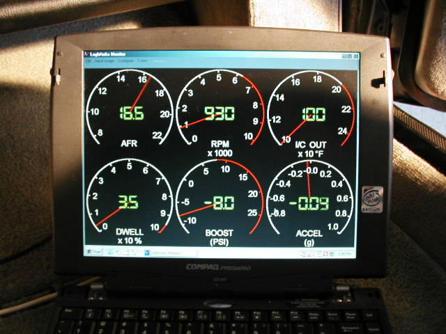
Z, again, thanks! Im just heading out the door to play. Its suppose to rain tomorrow and over the next few days. I want to try and log a few "jaunts".
Brain, PM me when you go to install it. I have it all dialed in now except for my Thermocouple input. Im trying to read the Intercooler discharge temp. I can read it already on my thermocouple meter but it doesnt have data logging like the LM3 does....it does have a MAX hold feature though. Once i get that figured im going to run my Thermocouples through a 4way swicther so i can log any 4 places...airfilter...SC Inlet, SC outlet...Intercooler outlet..with out unhooking all the T-couple wires each time.
Also join the FORUMS that INNOVATE has for the various devices....they are VERY helpful!
 01-07-2005, 04:15 PM
#17
Addict
Lifetime Rennlist
Member
Lifetime Rennlist
Member
Thread Starter
Well for what ever reason my RPM signal crapped out on me last night before i went for a drive. Im using and inductive clamp and for whatever reason, it wasnt working.
So today, since its SNOWING out I decided to hardwire the RPM signal to the LM-1 / Aux box. With help from the shcematics, WSM and emails to John and Rich, this is what i did.
This is on an 87 S4 auto.
I used the tach signal from the EZK.
Per WSM and schematics...Pin13 is "speed pulse to LH1" Meaning its the Rpm signal sent to the LH pin1
Looking on the schematic i found the color of the wire that leads between these pins. Its BL/WS (Blue/white)
I had previously removed some of the black sheathing from the EZK harnes as well as the LH to expose about 1 1/2' of wiring in the harnes.
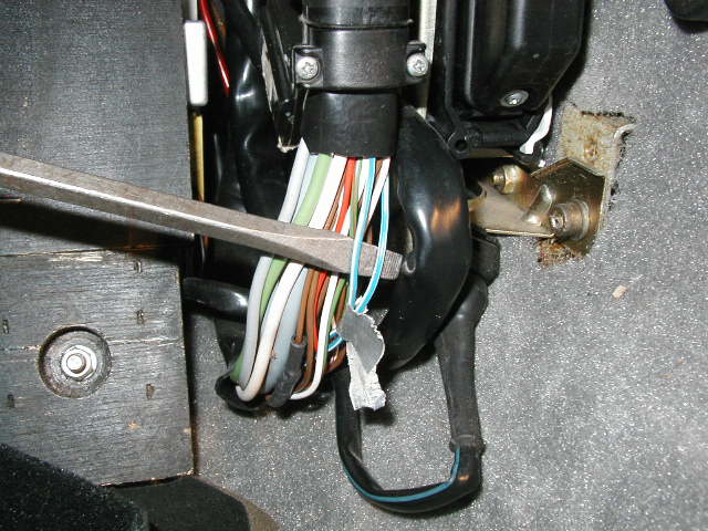
The problem then became that there were 2 Blue/White wires on the EZK and 3 on the LH harness playing the odds i used the EZK as it only had 2 to pick from  and its harness was the easiest to work with.
I took both blue/white wires and removed 1/4" of insulation from around them.
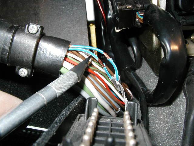
I set the ---FUNCTION--- on the AUX box CH1 to "1" as the engine redline is below 10000rpm
I took a test lead and connected Aux box CH1+ (RPM) to one of the wires (waiting for a big bang ). Just pick one.
I looked at my RPM screen on Logworks and the RPM was being displayed. However it was WRONG compared to my TACH.
I then set/pressed the ---CALIBRATE--on the AUX box for CH1. It will scroll through the following numbers/letters. " 1 2 3 4 5 6 A C" (this is in the manual BTW)
I simply kept pressing the CALIBRATE button until the correct RPM was displayed on the LOGWORKS screen.
The key here is...
with the test lead on one of the blue/white wires you will set CH1 calibration to "4"
If you place the test lead on the other blue/white wire you will set CH1 calibration to "2"
WHY THIS IS I HAVE NO IDEA!! I just came across it when i decided to attatch the lead to the other wire to see if there was an RPM signal there also, there was but it needed a different calibration.
In a nut shell, i used the wire where i set the CALIBRATION to"2" on Ch1.
I revved the car up and it works VERYWELL! However, i cant test drive it as we have 1/2 snow (and increasing) on the ground and 375ftlbs doesn t agree too well with asphalt let alone SNOWY ashphalt!
For those with an LM1 and Aux box, i hope that helps.
So today, since its SNOWING out
I decided to hardwire the RPM signal to the LM-1 / Aux box. With help from the shcematics, WSM and emails to John and Rich, this is what i did.This is on an 87 S4 auto.
I used the tach signal from the EZK.
Per WSM and schematics...Pin13 is "speed pulse to LH1" Meaning its the Rpm signal sent to the LH pin1
Looking on the schematic i found the color of the wire that leads between these pins. Its BL/WS (Blue/white)
I had previously removed some of the black sheathing from the EZK harnes as well as the LH to expose about 1 1/2' of wiring in the harnes.
The problem then became that there were 2 Blue/White wires on the EZK and 3 on the LH harness
playing the odds i used the EZK as it only had 2 to pick from and its harness was the easiest to work with. I took both blue/white wires and removed 1/4" of insulation from around them.
I set the ---FUNCTION--- on the AUX box CH1 to "1" as the engine redline is below 10000rpm
I took a test lead and connected Aux box CH1+ (RPM) to one of the wires (waiting for a big bang
). Just pick one. I looked at my RPM screen on Logworks and the RPM was being displayed. However it was WRONG compared to my TACH.
I then set/pressed the ---CALIBRATE--on the AUX box for CH1. It will scroll through the following numbers/letters. " 1 2 3 4 5 6 A C" (this is in the manual BTW)
I simply kept pressing the CALIBRATE button until the correct RPM was displayed on the LOGWORKS screen.
The key here is...
with the test lead on one of the blue/white wires you will set CH1 calibration to "4"
If you place the test lead on the other blue/white wire you will set CH1 calibration to "2"
WHY THIS IS I HAVE NO IDEA!! I just came across it when i decided to attatch the lead to the other wire to see if there was an RPM signal there also, there was but it needed a different calibration.
In a nut shell, i used the wire where i set the CALIBRATION to"2" on Ch1.
I revved the car up and it works VERYWELL! However, i cant test drive it as we have 1/2 snow (and increasing) on the ground and 375ftlbs doesn t agree too well with asphalt let alone SNOWY ashphalt!
For those with an LM1 and Aux box, i hope that helps.
01-07-2005, 08:18 PM
#18
Intermediate

Join Date: Oct 2004
Posts: 29
Likes: 0
Received 0 Likes
on
0 Posts
with the test lead on one of the blue/white wires you will set CH1 calibration to "4"
If you place the test lead on the other blue/white wire you will set CH1 calibration to "2"
If you place the test lead on the other blue/white wire you will set CH1 calibration to "2"
In european cars they use a lot of 2 color wires. Usually one stripe is smaller than the other. The order of colors is usually wide stripe/thinner stripe.
The calibrations in the Auxbox RPM settings refer to the equivalent number of cylinders for a 4-stroke (ign. pulses/rotation) if every ign. pulse is seen by the LMA-3.
The numbers mean:
1 One pulse for every other rot. (like 1Cyl)
2 One pulse every rot. (like 2Cyl)
3 1-1/2 pulses per rot (like 3 cyl )
4 Two pulses/rot (like 4 cyl)
5 2-1/2 pulses per rot (like 5 cyl )
6 three pulses/rot (like 6 cyl)
8 4 pulses/rot (like 8 cyl)
A 5 pulses/rot (like 10 cyl)
C 6 pulses/rot (like 12 cyl)
(When setting to '4' this is equivalent to a 4-cyl 4-stroke with 2 pulses/rotation. When setting to '2' this is like a 2-cyl 4-stroke with 1 pulse/rotation. This signal (in your case) might be coming from the TDC sensor.
Regards
01-07-2005, 08:28 PM
#19
Addict
Lifetime Rennlist
Member
Lifetime Rennlist
Member
Thread Starter

Im not sure of a lot of the PFM behind it all Klaus but it works now!
As far as the wiring colors, i have the Shop manual schematics on CD PDF. (
 Jim M!!) and there are multiple wires of the same color leading to and from the "brains".
Now I just need to get that pesky T-Couple set up to work.
01-07-2005, 10:56 PM
#20
Rennlist Member
Join Date: Dec 2002
Posts: 1,051
Likes: 0
Received 0 Likes
on
0 Posts
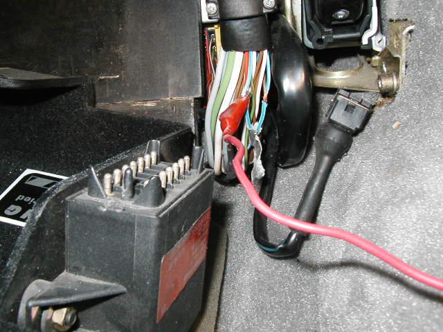
One of those two blue/white wires coming out of the EZK plug and going to the LH is a load signal (EZK pin 9 to LH pin 25). The other blue/white wire is the engine speed signal going from the EZK to the LH. (EZK pin 13 to LH pin 1). Although either of the two blue/white wires you have seem to work now, you really should make sure you have the correct one. (EZK pin 13 to LH pin 1). While the load signal may appear to work when reving the engine some in neutral, it's probably not going to be accurate once you really put your foot to the floor. To check if you've got the right one, you can either remove the back cover from the EZK plug and trace the wire to pin 13, or you can check for continuity between pin 13 and the spot where you removed the insulation on each of those two wires. Do that with an ohm meter while you have the plug disconnected from the EZK.
01-07-2005, 11:42 PM
#21
Addict
Lifetime Rennlist
Member
Lifetime Rennlist
Member
Thread Starter
Eh...I will see. I was just goign to cut the darn thing to see if the motor would quit! Either that or i loose 25' of timing real quick! Then i thought that splicing it all back would be a bi$#h so i just tapped onto it.
The covers on those are removable? How?
Why didnt i think of that. You da man. I will check later.
The covers on those are removable? How?
or you can check for continuity between pin 13 and the spot where you removed the insulation on each of those two wires. Do that with an ohm meter while you have the plug disconnected from the EZK.
01-08-2005, 12:42 AM
#22
Rennlist Member
Join Date: Dec 2002
Posts: 1,051
Likes: 0
Received 0 Likes
on
0 Posts
Originally Posted by Tony
The covers on those are removable? How?
01-08-2005, 02:23 AM
#23
Addict
Lifetime Rennlist
Member
Lifetime Rennlist
Member
Thread Starter
Thats good to know. I never really looked into taking it apart as it appeared sealed...as in molded around the contents in side.
I drove to the gym tonight and the RPM seems to work great. I really couldnt load it up as the roads were cold and wet.....so far it does works though.
I drove to the gym tonight and the RPM seems to work great. I really couldnt load it up as the roads were cold and wet.....so far it does works though.
01-18-2005, 02:43 AM
#26
Addict
Lifetime Rennlist
Member
Lifetime Rennlist
Member
Thread Starter
Rob...Z...
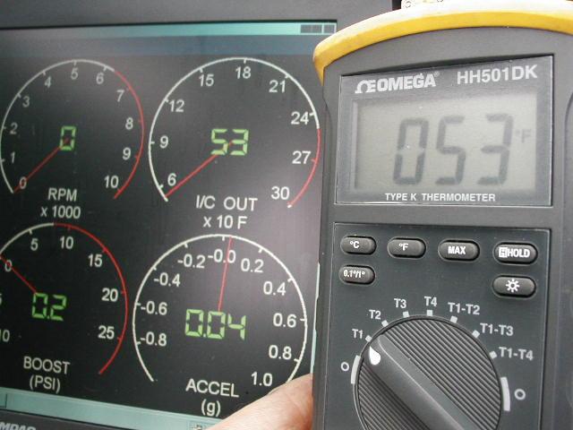
Moves when i blow on the sensor
Logs,
Plays back
and using the "slew" in the config is set to the K-thermocouples.
Z, the data for the 1ohm resistor was pretty much right on! I think ended up slewing it only a 1/10th or two of a volt?? I just moved the slide bar until the temp was the same on logworks and the "yellow" temp meter. I think it was only 2-3'f difference.
Now to get the driverside injectors firing and back on the road.
It should prove really fun to play with
Ive got the SC outlet, inlet and airfilter all prewired with the same GM sensor now. With the config in Logworks i could technically log and display all 4 temps at the same time if i wanted. Its really a waste of the AUX box resources as it would tie up 4 channels used for more important things but i will probably do it for a couple of WOT runs somewhere to see what temps are doing across the SC and intercooler.
AS you can see it would be pretty cool to be able to log Knock occurances as i could pin point what temps i could expect them at. Granted there are other variables to knock but the inlet temps are probably going to be the ones that will change the most.
01-18-2005, 01:11 PM
#28
Addict
Lifetime Rennlist
Member
Lifetime Rennlist
Member
Thread Starter
Hey Rob
Im pretty much thinking that i got some of the wiring wet in the back of the engine. It happened when i removed the manifold and disconnected the I/C hose. Ive removed most of the outer plastic on the harness back to appx the heater valve area. I did this to check the wiring connections and to now help dry out any moisture that may be there. I will know for sure when i bolt it all back up again and tuen the key. A PITA but it is pretty easy to install on and off.
In the meantime i ordered 8 bosch clips with wiring from a guy on ebay...25 bucks!! cant go wrong with that deal! Im replacing all the old injector conector wiring. Clip and splice!
All the checks on the wiring i have done seem to be OK. Im thinking its a "wet" and ground issue. I will see.
Im also getting my cat bypass pipes welded up with 2 "glass packs"
Should take the edge off a bit.
Ill be on the road again soon enough
01-18-2005, 05:38 PM
#29
Rennlist Member
Join Date: Dec 2002
Posts: 1,051
Likes: 0
Received 0 Likes
on
0 Posts
Looks like you're all ready to go with the LM-1.
Just in case anyone might want to use the information in the future, you mean the 1K ohm (1,000 ohms) resistor.
Originally Posted by Tony
Z, the data for the 1ohm resistor was pretty much right on!
01-18-2005, 08:22 PM
#30
Addict
Lifetime Rennlist
Member
Lifetime Rennlist
Member
Thread Starter
yeah, that one.
1k Ohms.
My next objective is to track down the voltage values for the FP gauge..or like you did, place a known pressure on it and take readings.
I could actually do that pretty easy.
Have the fuel pump run via my swicth...adjust the regulator...read the FP...read the voltage...repeat for every 5psi from 40 to 100psi.
sound feasable?