A/C Compressor Clutch Relay
#1
Regarding the very helpful 928GT.com chart at: http://928gt.com/928specs/78-79relay.htm
It lists both the Headlight washer AND A/C compressor relay as part number 928.618.111.00
Is this correct? In other places (928intl's online catalogue for example) the compressor relay is listed as 928.618.105.00
I was interested to know what the correct PN is and also if the relays are similar enough to be interchanged.... the PO had inserted a VW headlight washer relay in place of the compressor

#2
That part is a special speed relay. It's not interchangeable with a standard relay. It operates off of a pulsing tach signal and closes the contact when the engine is turning fast enough. Make sure you are getting the signal from the control head, and that you freeze switch and pressure switch are OK. These do not control the relay, but rather the circuit that is switched on/off by the relay may be interrupted at any of these points. I highly recommend that you consider putting a power relay in there to make the head unit & hard-to-obtain speed relay last longer. Details on my site, on the "AC chillin" page.
#3
Thanks sharkskin.... I'll have to check that out.
I'm getting 12v to the MAIN Power socket (P) for the relay when the A/C switch on the console is on(is that right?). It seems like that should be a constant source. Then, like you stated, I need to check the other switches... I dummy tested the valve to see if there was any pressure and there didn't seem to be any.. so obviously the low pressure switch is probably doing it's job. I have not yet inspected the freeze switch... where is this located approximately?
As far as everything else goes, the compressor does turn when you put power to it... so hopefully I'll have something to play with when I get a good relay in it and get a charge in the system... although I guess Im going to have to aquire some R-12.
#4
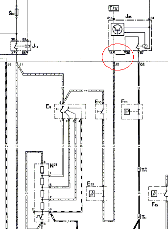
I looked at the 79 circuit diagram, and it looks functionally identical to the 78 in this area:

Ignore the red circle. That's where my problem was. But check for continuity beteen pin 87 on that relay and connector Q2. Make sure there is no voltage on the wire before connecting an ohmmeter... safest is to disconnect the battery. If you have continuity there, the panel is OK. With the relay in place and the engine running, you should see 12V at Q2.
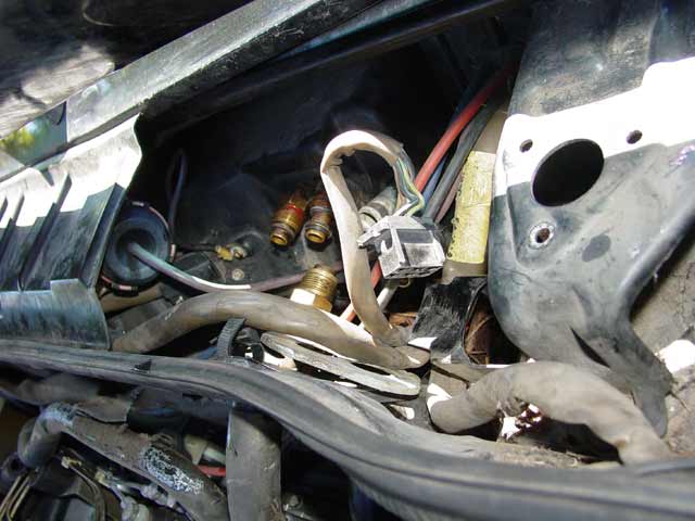
The freeze switch is under the plastic rain shield, beyond the round vacuum servo shown in this pic:

Pull up on the front of the rain shield to gain access. The freeze switch is normally closed, and the switch opens when the evaporator temp approaches freezing. You won't be able to verify operation till you get the system charged, but for now you should have continuity across the two terminals of the switch.

Ignore the red circle. That's where my problem was. But check for continuity beteen pin 87 on that relay and connector Q2. Make sure there is no voltage on the wire before connecting an ohmmeter... safest is to disconnect the battery. If you have continuity there, the panel is OK. With the relay in place and the engine running, you should see 12V at Q2.
The freeze switch is under the plastic rain shield, beyond the round vacuum servo shown in this pic:

Pull up on the front of the rain shield to gain access. The freeze switch is normally closed, and the switch opens when the evaporator temp approaches freezing. You won't be able to verify operation till you get the system charged, but for now you should have continuity across the two terminals of the switch.


