When you click on links to various merchants on this site and make a purchase, this can result in this site earning a commission. Affiliate programs and affiliations include, but are not limited to, the eBay Partner Network.
Hi,
My first posting here, so some intro first. I bought 87 928 S4 automatic with Murf super charged last October with my son. Car had been standing since 2008 and needed some basic maintenance. We did service dept restore kind of service last winter replacing "all" gasgets and seals, cam chains, timimg belt, vacuum lines, water pump etc and fixed some electric lines on engine compartment. There were evidences on some fire happening near right fuel rail. There is still things to do for next winter as well, but we have been able to enjoy driving this summer. One still disturbing feature is coolant temperature warning light with assosiated central warning light.
We had problems with original temp sensor as it was stuck and broke when uninstalling, new one broke when installing (snapped much before specified tightening torque) second new one was totally dead and now third new is perhaps behaving strange. We did test temperature dependent resistance of it before installation but we did not test alarm side.
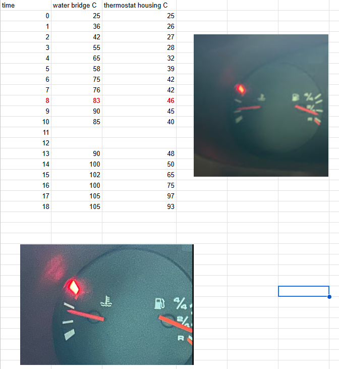
Problem is that light lits on much before temp gauge gets to horizontal position. We did a test starting motor cold, running idle, expansion tank cap open and measuring temperature from water bridge and thermostat housing using IR. Light appears on water bridge temp 80 C / thermostat housing 46 C. After the test we figured out that perhaps we should have looked at when cooling fans start as well if those have some influence on light. Is this third new sensor broken as well or what could cause light to appear this early? We have tested coolant level sensor to operate correctly.
There are three temperature sensors on the S4 Viz:
1. The sensor that generates the indication on the dash panel and is located on the water bridge.
2. The temp2 sensor that generates two signals that are blind and are used by the LH and EZK computers to set engine management parameters.
3. The sensor on the front lower driver's side of the radiator end tank- this sets the fan speed and is blind to the driver.
Please take a photo of the sensor you refer so we can understand better the item you refer .
AFAIK the high temperature alarm is generated from the temp2 output signals and should trigger at somewhere around 110C.
The coolant temperature exiting the water bridge on its way to the radiator should be 98C and the temperature difference radiator in to radiator out should be in the region of 8C to 10C on a correctly behaving S4. The motor is not fully warmed up until that difference is achieved and to get fully warmed up should take about 3 minutes or so .
The fuelling and ignition maps are modified until the temp2 output reaches 80C and they are at normal working values.
Based on the above it is clear that there is something wrong with the high temperature alarm setpoint. I would also suggest that the fully warmed temperature of 105C is also higher than it should be.
The obvious thing you need to be aware of is the accuracy of your temperature gun. If you are going to use such devices that are often inaccurate you should first calibrate the device against a pot of boiling water that should read 100C at sea level .
Trust the above helpful for starters.
is the water bridge powder coated? if so then it could have a bad ground .
NOTE the temp sensor for the dash is the one to right on the WB as your facing the engine.
The one to the left as your facing the engine is for the engine computers its called the temp 2.
NOTE snapping off any of these sensors indicates an installation error.
NOTE getting erroneous reading indicates a poor connection or a shorting in the harness usually at the 14 pin connector,
or bad ground path. or lastly a bad sensor.
This can be caused by a powder coated water bridge housing,
the bolts are the only way the WB is capable of being grounded.
Please post some pictures of the engine bay to get more accurate results in our guesses
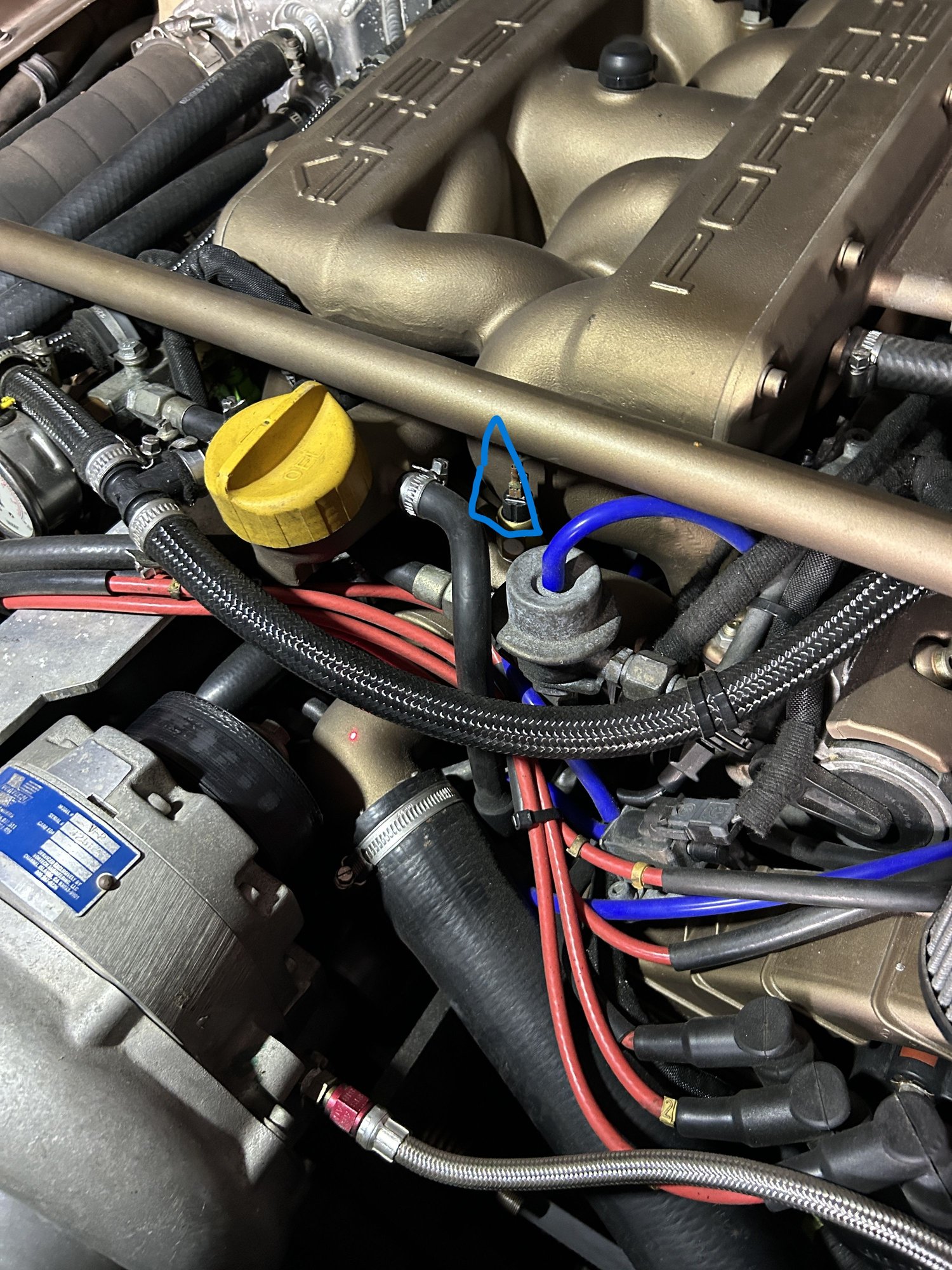
As I'm reading your responses, it might be a grounding problem. WB is ceracoted and ceramic is insulating material as well. Attached are the pictures I took from IR temp measurement points and the sensor we have suspected to be faulty is the one visible behind regulator.
Juha
Ok, looks like we have been troubleshooting wrong sensor.
Next step to check temp2 sensor and groundings for temp2 sensor. It might take some time before my next update.
Ok, looks like we have been troubleshooting wrong sensor.
Next step to check temp2 sensor and groundings for temp2 sensor. It might take some time before my next update.
Thanks
Juha
If there is a problem with grounding the body of the temp2 sensor the resistance to ground will be artificially high and the computers will thus be think the engine is colder than it actually is and thus will not cause a high temperature alarm. The motor would also run rich as it will still be operating using values from the warm up maps.
I tried to improve grounding yesterday temporary with bare copper around sensor body connected to grounding point without effect.
There is a running rich problem (trying to buy own Sharktuner to check mods or primarily planning standlone ECU + new harness for next project) as well, but I thought it is a separate issue not related to temp warning light because I was troubleshooting wrong sensor, but now it looks like all problems are related to same harness damage.
I'll need to measure resistances from LH and EZK connectors to check that connectors coming from LH and EZK are not short circuited. Based on resistance values https://jenniskens.livedsl.nl/techni...1/MyTip143.htm I calculated that if resistances are parallel due to damaged insulation then LH, EZK and warning light operation see equivalent resistance of 110 C already on real temperature of 80 + degrees as they now do and that would explain all problems ie. early warning light and running rich.
Juha,please reread this .your response indicated you have things backwards.
is the water bridge Cera/ powder coated? if so then it could have a bad ground .
NOTE the temp sensor for the dash is the one to right on the WB as YOUR FACING the engine.
The one to the left as your facing the engine is for the engine computers its called the temp 2.
NOTE snapping off any of these sensors indicates an installation error, maybe using the wrong tools.
NOTE getting erroneous reading indicates a poor connection or a shorting in the harness usually at the 14 pin connector,
or bad ground path. due to the bolts not providing a proper ground, or lastly a bad sensor.
Bad ground can be caused by a powder coated water bridge housing,
the bolts/washers are the only way the WB is capable of being grounded.thus the washers have to clamp to bare metal .
Your talking about instrument readings this is handled by the sensor on the water bridge to the right as you face the engine.
clean the clamped surfaces to bare metal where the bolt head / washer contact ,
spray with deoxit 100
Checking the temp2 sensor is easy- remove the plug and measure the resistance to earth of each pin. When cold the reading should be about 4k ohms and when at operating temperature it should be about 200 ohms . Both channels should read exactly the same values. I think the wsm has a list of values against specific temperatures. If the sensor checks out ok you should then measure the resistance at the LH and EZK plug terminals so as to ensure the readings are the same as they are at the sensor.
Ok,
We measured temp2 sensor, resistances ok. Measured resistances also from LH and EZK connectors when cold and when warm. All measurements for temp2 sensor look ok with and without wire harness. Motor is running rich, but I assume it is due to programming and there is a plan for next winter.
We returned back to sensor for dash, the one we started with. After studying a bit on circuit diagrams we figured out that one pin goes to gauge and another pin to central warning unit. We took off wire from narrow connector of the sensor and light disappeared, but gauge was still indicating ok. Now we have understanding that there are two different resistances on dash sensor and that sensor has broken warning light resistance.
Thanks
You triggered something in the back of my mind in your latest post and for sure the alarm is triggered by the dash panel sensor as I could figure out now that I am back home and have ccess to y wiring diagrams.
The sensor on my later digi dash model has only one pair of cables and the second cable is grounded via the dash panel that has a built in trip alarm feature - what this means is that it sees a signal, recognises it is in the alarm state and annunciates such on the built in alarm annunciator panel. Your model does not have this feature so your sensor has two cable outputs- one analogue and one for the alarm lamp and it is earthed via the body.
Given the testing you did it would seem that the alarm contact is making contact prematurely but no idea why other than some kind of failure.
Are you sure you are using the correct part number for the sensor? As I recall, the sensor has a smaller spade terminal for the over-temp switch. The sensor pictured above has equal size large terminals.
Are you sure you are using the correct part number for the sensor? As I recall, the sensor has a smaller spade terminal for the over-temp switch. The sensor pictured above has equal size large terminals.
Yes, terminals have different widths despite photo giving wrong illusion. I needed to go and check terminals I'm rather assured about the sensor type. This sensor is kind of aftermarket crap because local Porsche parts dealer did not have better to give for warranty of original sensor.


 I'm rather assured about the sensor type. This sensor is kind of aftermarket crap because local Porsche parts dealer did not have better to give for warranty of original sensor.