When you click on links to various merchants on this site and make a purchase, this can result in this site earning a commission. Affiliate programs and affiliations include, but are not limited to, the eBay Partner Network.
Update on aftermarket HVAC flap and heater control solenoids
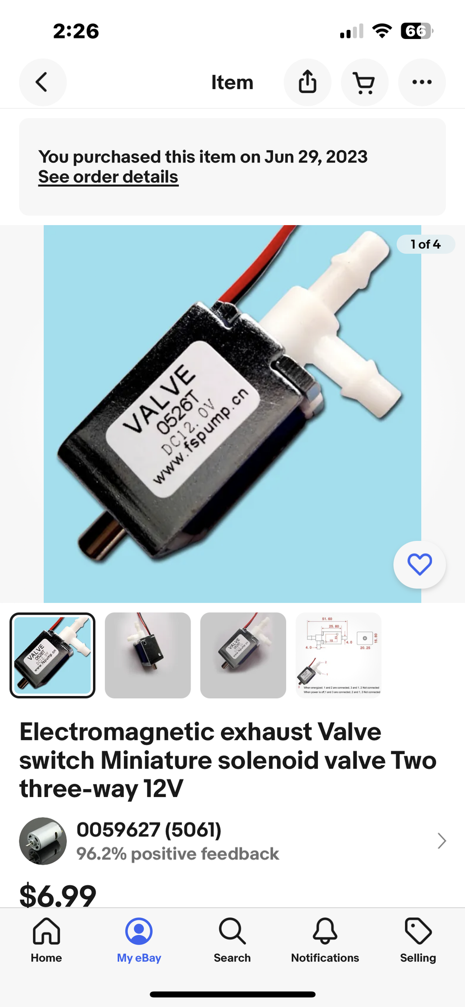
So, in completing climate control cold/heat functionality; I’ve employed an aftermarket solenoid for controlling the heater valve. The prognosis is good. Temperature control works very well.
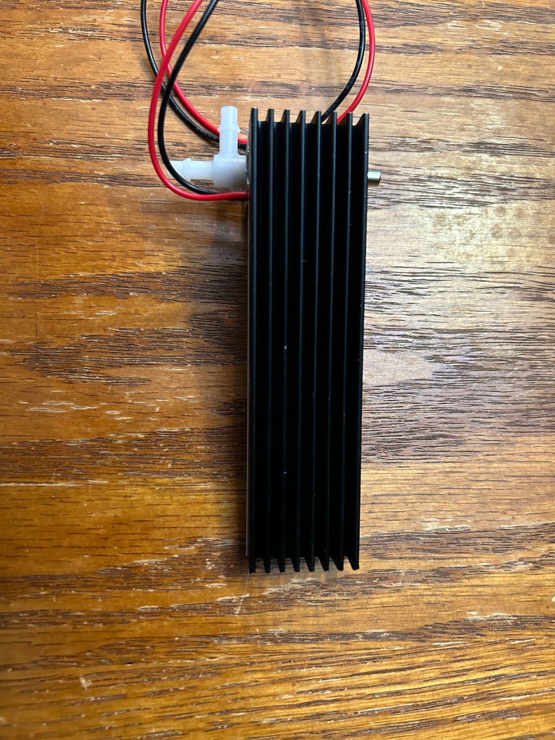
I won’t be replacing the flap control solenoids and vacuum bladders until the dash is out this winter, so the heat sink that mounts the solenoids only presently has the single heater valve solenoid in it. But will have more company later this winter.
I can hardly believe HVAC is operational, leak free after 17 years.
I'd measure how much current it actually takes in the active state? then we will know the power dissipation.
Alan
So, here are the readings;
Bear in mind my non-OEM part is new, the OEM part is 37 years old.
Both new and old solenoids are operational. In anticipation of a question. I’m not putting 37 year old electro-mechanical-pneumatic parts back into a highly refreshed HVAC. This is just an alternative. Everyone must make up their own minds and choices.
The readings were taken over a 10 minute span for each, continuously energized, examining the current reading periodically for spikes or anomalies.
The hottest parts of the cases were read for temp at each time endpoint.
NEW (non-OEM) SOLENOID:
initial reading:
69 degrees, 181 ma
10 minute reading;
82 degrees, 164 ma
OEM (original) SOLENOID:
initial reading:
70 degrees, 286 ma
10 minute reading:
86 degrees, 240 ma
the coil temp of the OEM was unwrapped and exposed so the OEM coil temp could be read at the end of 10 mins as well. The OEM coil temp read 100 degrees. In fairness, the new solenoid coil was wrapped, so its coil temp reading wasn’t possible.
The new solenoid current readings was initially 1 ma above its rated current ( <180ma ), falling below that reading within a minute or so.
I'm assuming your degrees are in F? It seems if your mounting method is equivalent to stock from a thermal perspective - then there should be no major issue. We are looking at only slightly more than 2W dissipation.
It might be interesting to see how much voltage (and current) you need for the solenoid to stay latched after it switches - usually its quite a lot less then than the current required to initially activate.
It might be interesting to see how much voltage (and current) you need for the solenoid to stay latched after it switches - usually its quite a lot less then than the current required to initially activate.Alan
Alan, the 10 minute readings were taken with each solenoid fully energized for 10 minutes. Notice that for each, current fell with increasing temp. Maybe that’s just coincidental
Seems to me those units are not specifically designed to be used with a heat sink.
They are rated for use up to 55C so the test data you produced suggests no issues assuming you are measuring in degrees F. The behind the console location is not going to get too well ventilated so they will likely get a bit hotter than your test but there is still a margin there.
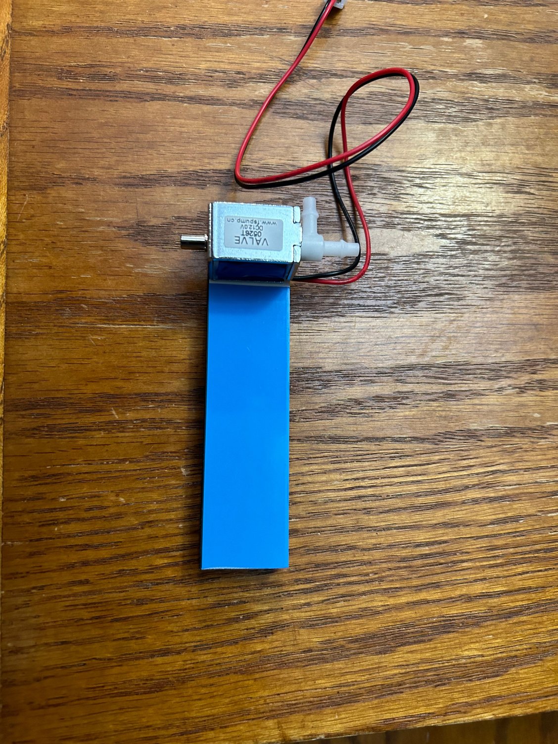
The heat sink should not do any harm albeit I am a bit puzzled as to what the blue "adhesive stuff' is - presumably designed to optimise heat transfer from the heat source into the sink in the same way that heat transfer paste does ?
Alan, the 10 minute readings were taken with each solenoid fully energized for 10 minutes. Notice that for each, current fell with increasing temp. Maybe that’s just coincidental
No not coincidental - as the coil warms up the coil wire resistance goes up (a small effect).
...The heat sink should not do any harm albeit I am a bit puzzled as to what the blue "adhesive stuff' is - presumably designed to optimise heat transfer from the heat source into the sink in the same way that heat transfer paste does ?
It is likely graphite loaded thermal tape - this has excellent thermal properties both as a dual contact transfer medium (e.g. to a heatsink) but also conducts well laterally as a heat spreader.
The heat sink should not do any harm albeit I am a bit puzzled as to what the blue "adhesive stuff' is - presumably designed to optimise heat transfer from the heat source into the sink in the same way that heat transfer paste does ?
hi Fred; the blue adhesive is a heat conductive adhesive component of the heat sink for adhering a part to the heat sink. I found that a small cable tie around the shoulder of the solenoid ties it hard and fast to the heat sink.
I no longer believe the heat sink is necessarily required, but it’s a convenient way to secure the solenoids to a plate-like mount and the heat sink will then be secured in place.
but I wouldn’t say that the original solenoids weren’t mounted to a heat sink. The plate the OEM solenoids were fastened too may have offered heat radiation opportunity for the OEM units
What I meant was - that if you use a variable power supply to activate the solenoid - you will then find you can then lower the voltage down before the solenoid will drop out. That voltage and its associated current would be interesting. Potentially of even more interest: at what lower voltage do the solenoids reliably activate anyway - especially when fully warmed up in usage. This might tell you could simply add a series resistance to the coil to lower the coil operating voltage & current further. Useful because power dissipation is proportional to the square of the voltage. But given your results this is hardly a critical issue
hi Fred; the blue adhesive is a heat conductive adhesive component of the heat sink for adhering a part to the heat sink. I found that a small cable tie around the shoulder of the solenoid ties it hard and fast to the heat sink.
I no longer believe the heat sink is necessarily required, but it’s a convenient way to secure the solenoids to a plate-like mount and the heat sink will then be secured in place.
but I wouldn’t say that the original solenoids weren’t mounted to a heat sink. The plate the OEM solenoids were fastened too may have offered heat radiation opportunity for the OEM units
Hi Mike,
i just came across something similar to the heat sink in Amazon UK so no issue there.
I went down a similar path a few years ago after learning that the solenoid valves were no longer available- they are in one of my spare parts bags gathering dust!
Just make sure you understand the porting arrangement correctly and I reckon you should be good to go. Power on routes vacuum to the item being evacuated and power off bleeds off the vacuum and isolates the source of the vacuum.
What I meant was - that if you use a variable power supply to activate the solenoid - you will then find you can then lower the voltage down before the solenoid will drop out. That voltage and its associated current would be interesting. Potentially of even more interest: at what lower voltage do the solenoids reliably activate anyway - especially when fully warmed up in usage. This might tell you could simply add a series resistance to the coil to lower the coil operating voltage & current further. Useful because power dissipation is proportional to the square of the voltage. But given your results this is hardly a critical issue
Alan
that’s an interesting point that I just missed. I used to have a “dial a voltage” bench supply. Back in the days when I was doing op-amps/digital filters… decades ago. But the only bench tools I have since those days is a soldering iron and a (newer) VOM


 10-19-2023 | 03:28 PM