When you click on links to various merchants on this site and make a purchase, this can result in this site earning a commission. Affiliate programs and affiliations include, but are not limited to, the eBay Partner Network.
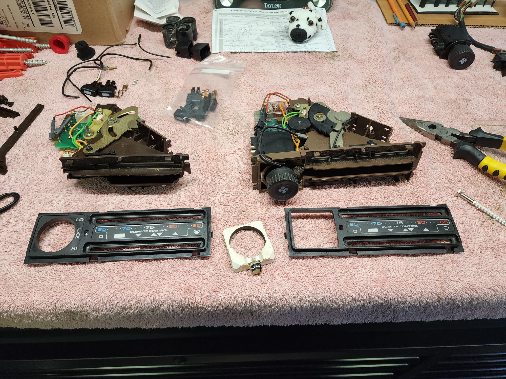
Last night I removed the climate unit to switch out the burnt out bulb inside and like many things with my 928 not everything is as it should be thanks to the previous owners. Pulled the unit out and I have two wires (circled in red) not attached to anything. I couldn't spot anything obvious.
Also, the what I assume are vacuum lines on the back, we're not all connected. Any help or insight as to what goes where, I see there are some green yellow and red lines back there.
Shouldn’t be any vacuum lines to the unit, that’s optical fibre for the sliders. Unless the PO did something very weird. There’s plenty of threads here showing the internals and with LED upgrades.
As mentioned, those "wires" transport the light from the collective light source where they all originate from to the sliders so you cns see the position of the sliders when the lights are on.
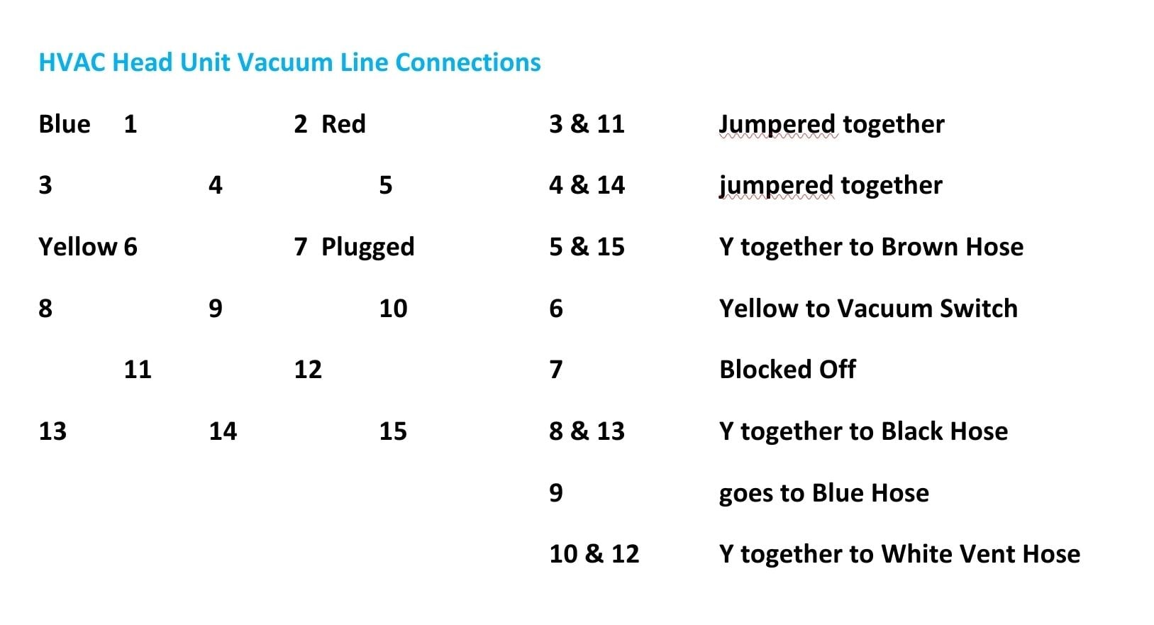
What does the back of the unit look like with the vacuum lines so I can see if the diagram I made for my 79 will work for your car?
As mentioned, those "wires" transport the light from the collective light source where they all originate from to the sliders so you cns see the position of the sliders when the lights are on.
What does the back of the unit look like with the vacuum lines so I can see if the diagram I made for my 79 will work for your car?
If you're looking at the back of the HVAC unit, this will then make sense for the vacuum connections. (These are from my 79 US car though so could be different than an 81)
Any advice for securing the cable that goes from the temperature slider mechanism out toward the driver side? There's the two notches but it doesn't want to stay seated, god knows how many times it's been taken in and out, and then the tension doesn't allow the slider to function properly. If I hold it by hand from behind and move the slider it works fine, so it needs to be secured to something.
Press the Fiber optic cable directly through the center of the plastic clip (back of the slider) and insert it in to the main body of the slider until it seats then pull it back a smidge.
Check you routing from the light source, making sure it doesn't get kinked or bound up with slider movement.
As for as holding it in the slider ****, clean the back of the slider as best you can with some alcohol, a dab of hot glue wont hurt anything, you can buy new sliders with new springs,
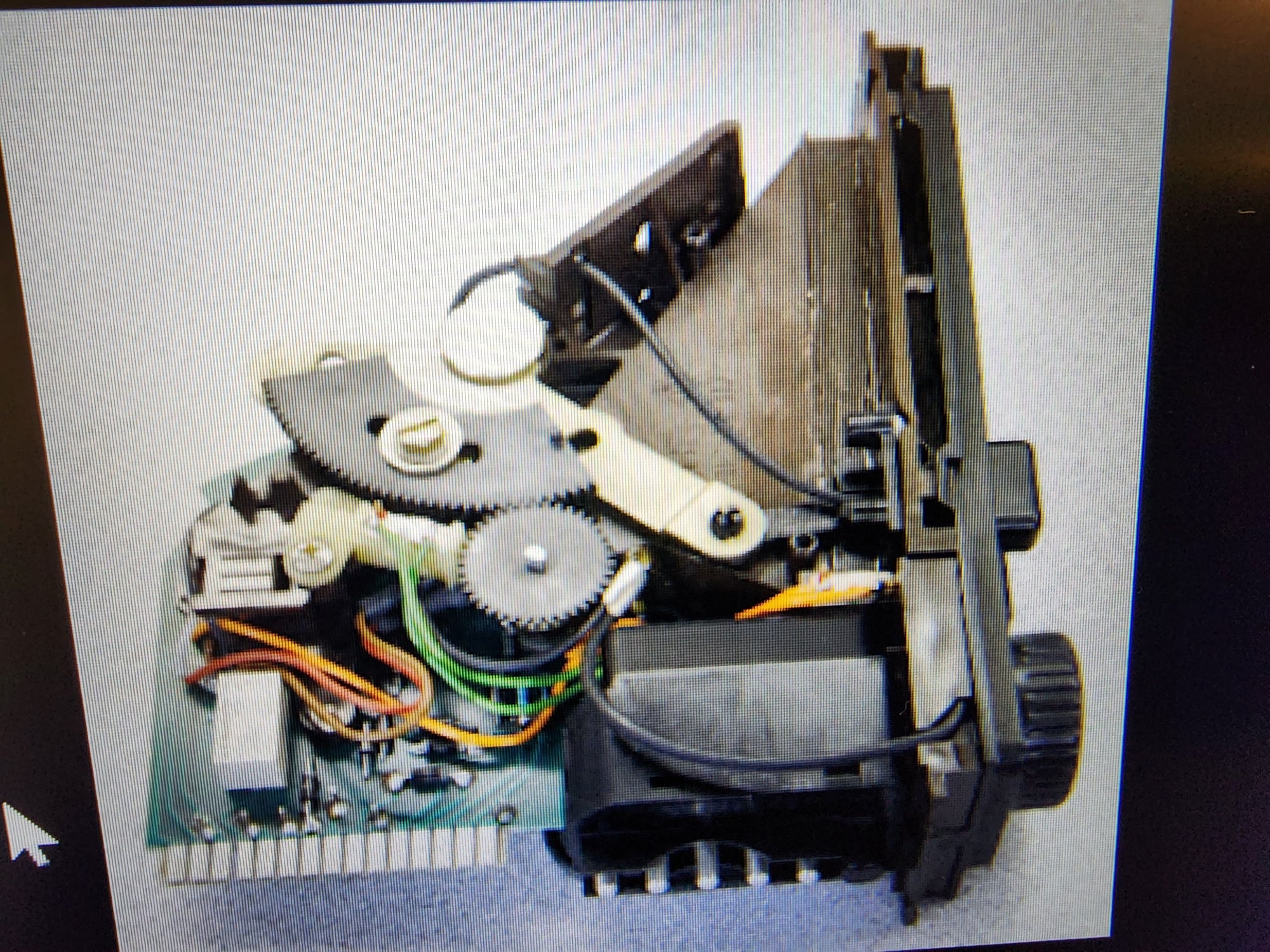
I just rebuilt a newer 1985 HVAC head unit last week it had two broken slider and a damaged fiber, I made one good one from a parts unit where the old plastic just crumbled, including the Black gears.
This Pic I found in a thread here showing proper routing of the fiber.
Press the Fiber optic cable directly through the center of the plastic clip (back of the slider) and insert it in to the main body of the slider until it seats then pull it back a smidge.
Check you routing from the light source, making sure it doesn't get kinked or bound up with slider movement.
As for as holding it in the slider ****, clean the back of the slider as best you can with some alcohol, a dab of hot glue wont hurt anything, you can buy new sliders with new springs,
I just rebuilt a newer 1985 HVAC head unit last week it had two broken slider and a damaged fiber, I made one good one from a parts unit where the old plastic just crumbled, including the Black gears.
This Pic I found in a thread here showing proper routing of the fiber.
I'm actually having trouble with this cable. Might have to use some hot glue or alternative to secure the black sheath part to the two brown tabs were it was pressed in originally. Otherwise it tensions improperly and will not stay on the hot side of the slider.