When you click on links to various merchants on this site and make a purchase, this can result in this site earning a commission. Affiliate programs and affiliations include, but are not limited to, the eBay Partner Network.
U'mmm No! The contacts are open until the resistor pack over heats, then the the bimetallic strip bends and closes the contacts creating a circuit that by-passes the resistor pack making the fan run at full speed. This allows the restore pack to cool from air flow and from not being utilized to reduce the fan speed.
Such a suggestion on your part demonstrates a fundamental lack of understanding of how the item in question actually functions. Which is no surprise to me.
You can share the information without the closing sentence...
There are 4 resistance coils in the blower resistor, marked 0.25, 0.4, 1, and 2.5 ohms.
Here's a closeup pic of the 4 coils and the marked resistances. Regarding the coils, I'd bet they're nichrome wire, in three different thicknesses and lengths as follows:
0.25 ohm coil: 0.9 mm wire (19 gauge), 8.25 mm OD coils, 4.5 turns
0.4ohm coil: 0.7mm wire (21 gauge), 7.8 mm OD coils, 4.5 turns
1 ohm coil: 0.7 mm wire: 9 mm OD coils, 11.5 turns
2.5 ohm coil: 0.5 mm wire (24 gauge): 11.2 mm OD coils, 12.5 turns
Can't be that hard to buy some nichrome wire and re-coil a dead unit (?)
Last edited by Rob Edwards; 12-16-2022 at 10:41 PM.
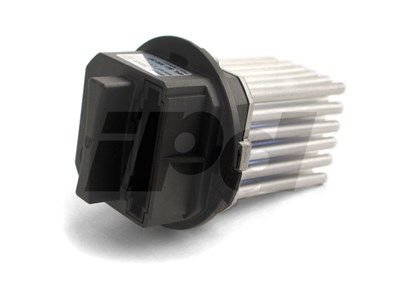
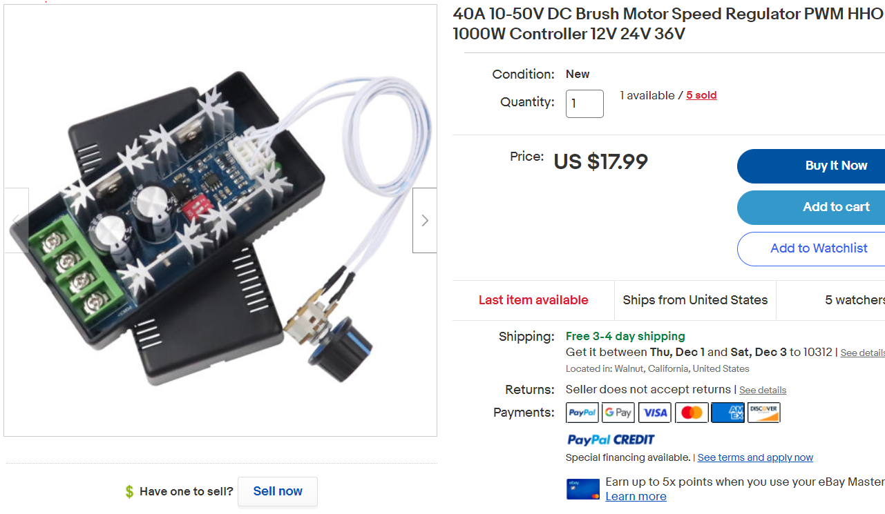
I used a PWM like the one pictured.
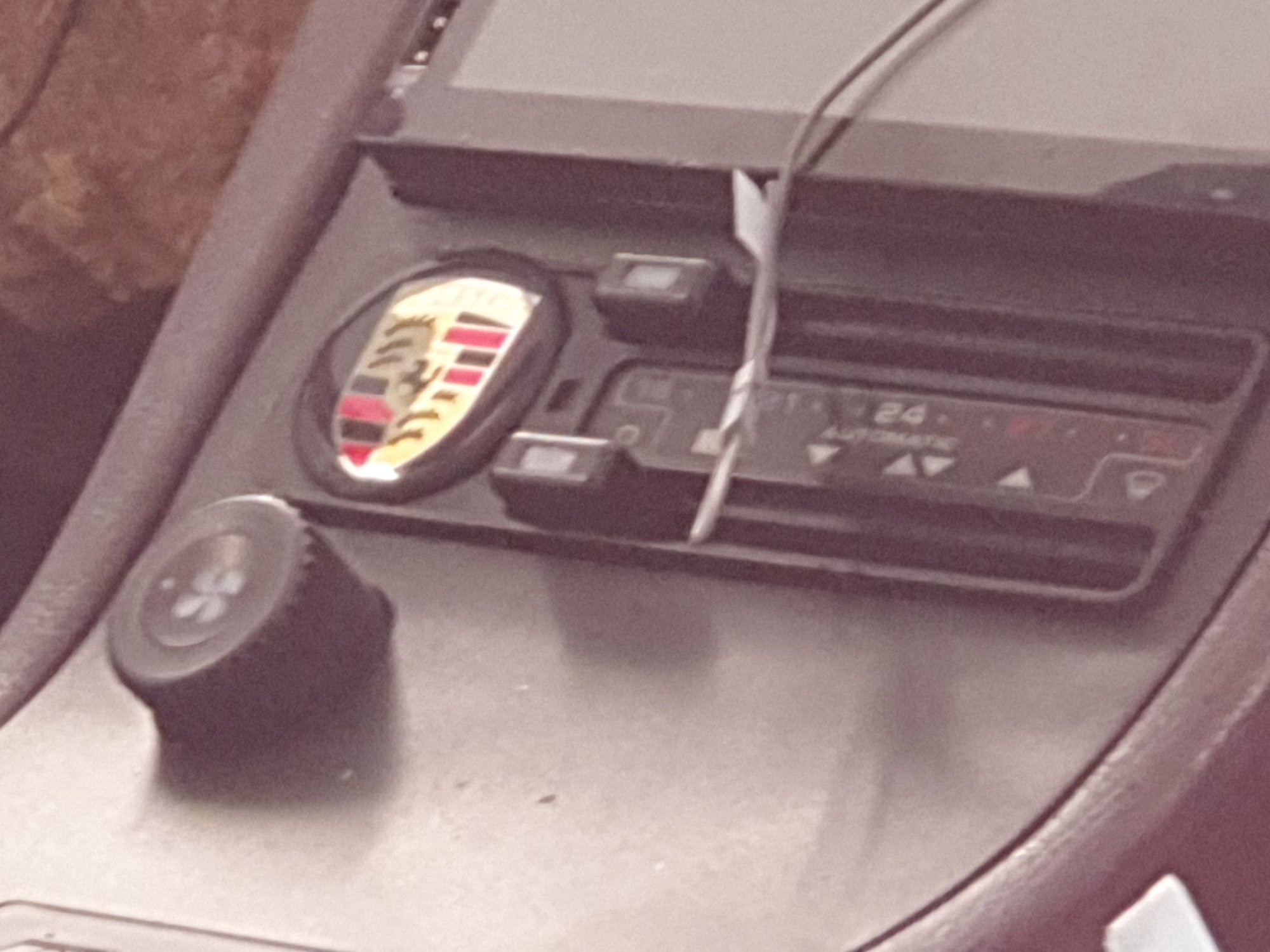
Couldn't get it into the original HVAC controller, so I fitted it in below and have now covered the old switch hole with a Porsche logo.
Has an 'off' position and runs the fan up and down with minimal current draw.
I have yet to prove the 'defrost' full speed function?? sits in a small box beneath HVAC Requires minor console work!
I think that's a better solution than mine. I got one with the pot soldered on the board which made mee move the ****.
This type you can mount anywhere and fit the pot in the original spot.
I ordered one like post 33. Simple solution. This was the reason behind the original post.
Alan
For an electrically challenged person like me who is looking for a solution for the 928 community how does this "simple" solution work with our HVAC?
Alan can you help?
__________________
Does it have the "Do It Yourself" manual transmission, or the superior "Fully Equipped by Porsche" Automatic Transmission? George Layton March 2014
928 Owners are ".....a secret sect of quietly assured Porsche pragmatists who in near anonymity appreciate the prodigious, easy going prowess of the 928."
I'm going to make a resistor bridge so we can use the 4 position switch. Will be simple. should position 1 be fan off? or low, but not so low as to be noisy, on the pwm system. yes, I could substitute the potentiometer for fan speed, but would like cabin controls to remain as designed.
Last edited by Alan 91 C2; 12-17-2022 at 09:17 PM.
I'd like to hear a smart person answer this also.
If a PWM controller like pictured above, with the pot able to be mounted in place of the original fan speed ****, the actual PWM controller can be placed anywhere behind the console.
I should have looked harder but as I was rebuilding the whole console, it didn't matter much in the end.
The unit I ended up with is good for 50amps but when I tested it on my re-lubed blower fan, it was full speed at a bit under 20amps. 18 amps by memory.
Using a resistor bridge driven by the original conductors to the factory resistor pack, solves several problems; no rewiring in the cockpit, and defroster still work in high speed, (with micro relay.)
I've ordered the PWM from post 33, thanks RamCram. When it arrives, i will see how the potentiometer is installed in the circuit. (for those who are interested, sometimes the potentiometer just parallels a resistor on the circuit board for preset speed, with no input, depends on the designer goals) The existing cabin circuit to remain as is, and control work to be done at the existing resistor unit, location. The defrost signal will have a new micro relay to simulate high speed, resistance equivalent, for the blower on high speed. To be worked out is the circuit location. Ideally placed in the resistor pack (enlarged?) hole, with new cover plate, to keep it out of the weather. (May be able to retain existing 8 pin connector, with donor female connector part from old resistor pack) So all new work at the resistor pack location..
As an aside, it would be nice to have a form factor small frame size for the PWM, to fit the existing hole, to be continued.
This version doesn't seem to be a great candidate to be in the plenum hole due to its size/format. I will assume you will direct drive the motor from the 2 motor feed connections on the module, so you'd need to use the stock blower motor ground (2.5mm^2) and a new (fused) 2.0MM^2(+) power feed to supply this module in the plenum area.
I understand your idea of wanting to maintain the stock switch operation, but since the blower switch is a combiner switch (not a selector switch) it acts more like a rheostat than a potentiometer. So some control configurations may allow that use but many may not - hope that works out for you.
Note that the DEF full speed mode is a separately wired connection direct from the DEF relay to the blower motor so you could modify that for use as your positive supply perhaps? (assuming a different way to get DEF full speed via PWM). You'd still also have the 4 wires from the switch to play with depending how you configure that.
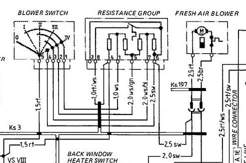
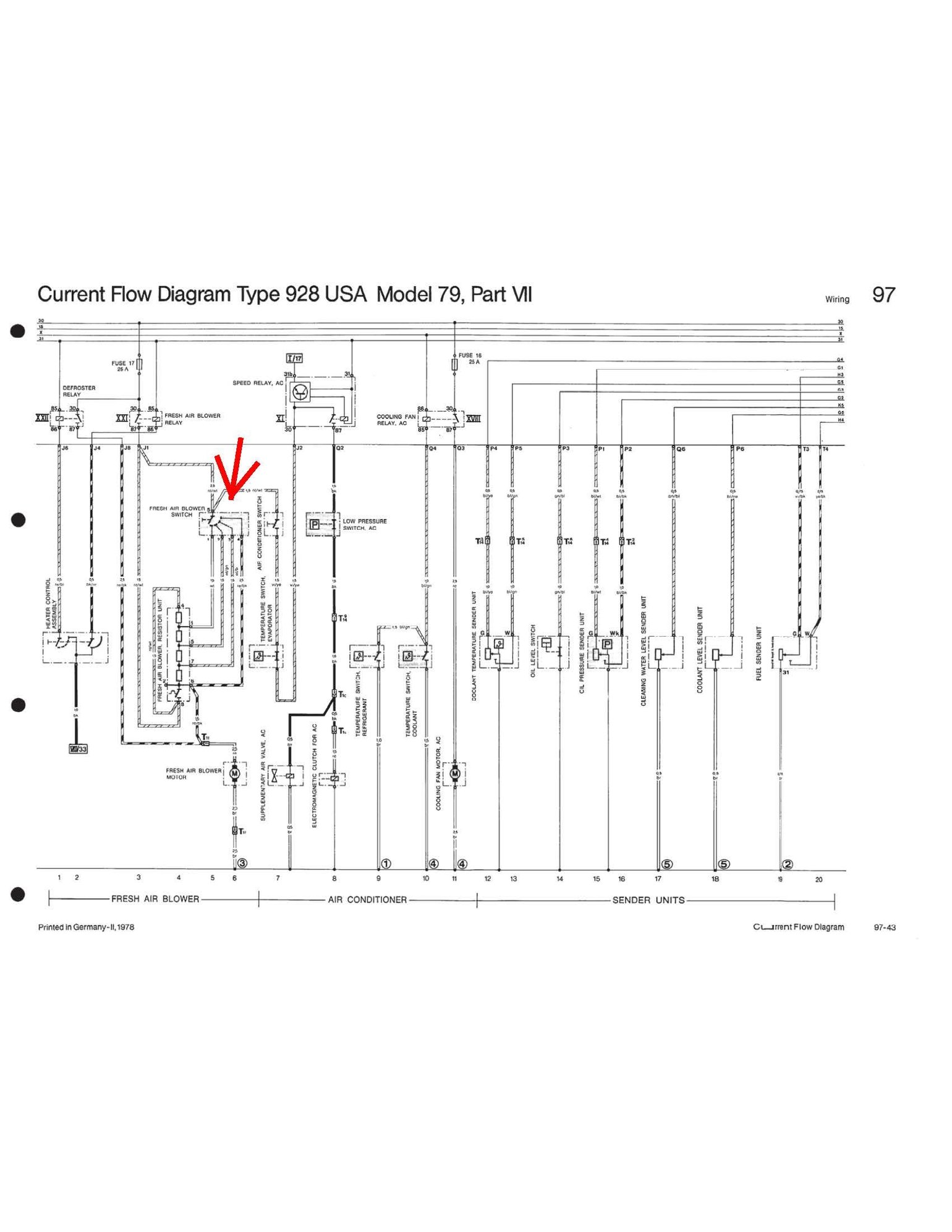
Unable to find a definition of a combiner switch I went to the wiring diagram. So position 1 closes one circuit, position 2 closes two, position 3 closes three and position 4 closes 4. So an input into a PWM controller would have to replicate the combination of the combination switch and the resistor network in the original resistor assembly.
My 79 schematic shows the switch to have individual segments for each speed selected. The combiner type switch can also be used with slightly different circuit. The benefit of the combiner type, is smoother transition between speeds.
Alan,
The rheostat versus potentiometer is two sides of the same coin, for this case. Technically the rheostat is series current carrying device. In this case, I want to repurpose the switch to function as a potentiometer with 4 discreet resistance values. Or three if the speed 1 is really off. And yes, this PWM package, may not be the one selected, as I would like everything hidden/protected in the HVAC plenum. In the combiner switch iteration, the parallel resistor for high speed would be selected to the parallel resistance values of all other speeds. For the defroster mode would just be a micro relay, from the defroster circuit switching in the same resistance input to the PWM, as our High speed selection. The motor loads, pwr and ground would come from the PWM. Power to the PWM would come from the existing supply 12V from the HVAC relay on pin 8 of the resistor plug. So all new work would be hidden behind the replacement resistor pack plate/ cover, including a micro relay (just a small frame 12V relay with 1A contacts, likely the size of the relay in the HVAC controller.).. There is one unused pin on the 8pin connector to be repurposed for the DEF speed, circuit. There will be three (or two) new conductors moving the power ground to the PWM, and maybe a PWM load ground to the motor, along with the DEF power signal to the micro relay. Should be able to use the 8 pin plug, easier if we make speed position 1, as OFF.
Last edited by Alan 91 C2; 12-20-2022 at 12:20 PM.
My 79 schematic shows the switch to have individual segments for each speed selected.
Ahh that helps then! - '78-'83 have that selector style switch blower switch while '84 to the end of production have the combiner style blower switch
I'd never really picked up on that difference before. This configuration change doesn't really make much difference for the stock blower resistor usage where it really is just a rheostat like configuration - so not sure why they even made the change?
Note to others with '84 or later cars - its not possible to use the later stock switch in the same manner Alan proposes - you may actually need to use a potentiometer instead of the switch.
This unit from Mahle/Behr is used in Volvos (prob. many others too). It is a fully variable PWM solution, not sure if includes the whole PWM circuit (minus a speed input) or is just the final drivers. Obviously it is intended for automotive use in the airflow path. Note It is physically rather larger than you might expect, similar in size to the 928 resistor pack but may protrude somewhat further into the plenum. Its fixing method in Volvos is a rotational lock.


 12-16-2022 | 09:31 PM


 George Layton March 2014