When you click on links to various merchants on this site and make a purchase, this can result in this site earning a commission. Affiliate programs and affiliations include, but are not limited to, the eBay Partner Network.
I've converted my 1987 928 to MegaSquirt. It was previously running and tuned on SharkTuner PEMs, with a mid-mount turbo and 11.6 psi of boost.
Attached is a spreadsheet with all of the LH/EZK to MegaSquirt wiring connections. Along with my personal notations on pins, letter codes, resistors, MAF/TPS/VSS/Hall/etc pinouts. And more.
Also attached is my initial tune. It does not include VE table adjustments from tuning under load. AE tuning is also not complete in the tune. And, most importantly, the fuel and ignition tables are scaled for 11.6+ psi of boost, which won't work well for most people. However, I came up with a method for converting stock ignition maps. Worst case, converted maps may need a little rescaling after some dyno/road logging.
I've attached these files for those who convert to an aftermarket ECU in the future and need to know some of the critical settings that work. Or, someone who just needs confirmation of OEM wiring. I tested every single wire of the OEM harness, and confirmed the OEM wire colors. The WSM is wrong on a few of them, but my spreadsheet has the correct colors, confirmed personally by me. Given that my OEM harness didn't match the factory documentation, I recommend that anyone else doing this also personally confirm the wires on their specific wiring harness. The WSM wiring diagrams can also be misleading, or difficult to interpret, as to which ECU connector some wires come together at. In general, if a connection goes to both ECU's, it is split/joined at the LH connector. It's all in the spreadsheet. But, confirm it for your situation, don't just rely on how my specific car was wired.
The car started on the first attempt and idled well.
A few highlights:
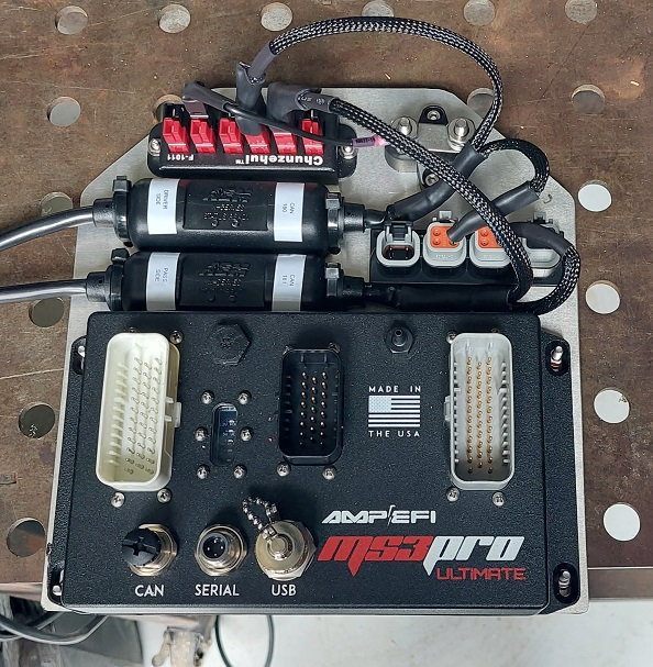
MS3Pro Ultimate (Made in the USA).
PMAS MAF and wrote my own program to convert their 37 point curve into a 64 point curve.
Switched the stock trinary TPS to a standard infinitely adjustable (potentiometer) TPS.
Came up with a method for converting stock ignition maps to work with MegaSquirt (or any other aftermarket ECU).
Works with OEM CPS and CAM/Hall sensors.
Adjustable tach output to get the dash tach dead on accurate.
Full sequential injection.
Dual CAN Bus wideband O2 sensors, one for each side of the motor.
Supports dual factory knock sensors.
Custom dashboards for both the PC and Android applications.
CEL and limp mode capability.
Flexible logic loops to control any device based on any parameters.
Fully customizable AFR target table for entire fuel table and supports closed loop for all AFR's/cells.
The MicroSquirt could probably be made to be plug and play and quickly/easily replace the LH/EZK's. At some point, that may become a necessary path for some cars or situations.
For me, the top tier MS3Pro Ultimate was the way to go. The feature set is impressive, build quality is excellent, and support is very good. Plus, it's one of very few ECU's that natively support MAF, allowing me to have a blended MAF/SD tune to get the best of both.
Bottom line...it works well. And it's very satisfying to have it fire up smoothly on the very first attempt.
Usually the hardest part about these aftermarket computers isn't the install, it's the tuning.
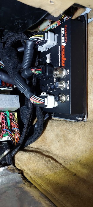
It's fantastic to hear that you have a solid base map for your application. That is one of the biggest hurdles in and of itself. Doesn't hurt that your install looks super clean as well!
@Bulvot - Thanks for the spreadsheet and the wiring tips. Could you please show some pictures of the connecting the MS harness to the factory sensors in the engine bay?
Which sensors, specifically, are you asking about? The spreadsheet has all of the connections detailed. Is there something in particular you're trying to figure out?
You are quickly becoming a pioneer in a similar but different way to Dwayne.
Like him you also share your findings, both successes and failures (and always provide info on the best alternative to joy)
As these cars get older we will all need alternatives to keep them running. Keep it up!
Attached are custom channels that I configured for TunerStudio. These give you two things:
1) On/Off knock detected flags for each of the 8 cylinders
2) Records the actual knock threshold being applied by the ECU
This makes it very easy to look at a log and see where knock was detected, then zero in on that time frame to see what was happening that triggered the detection.
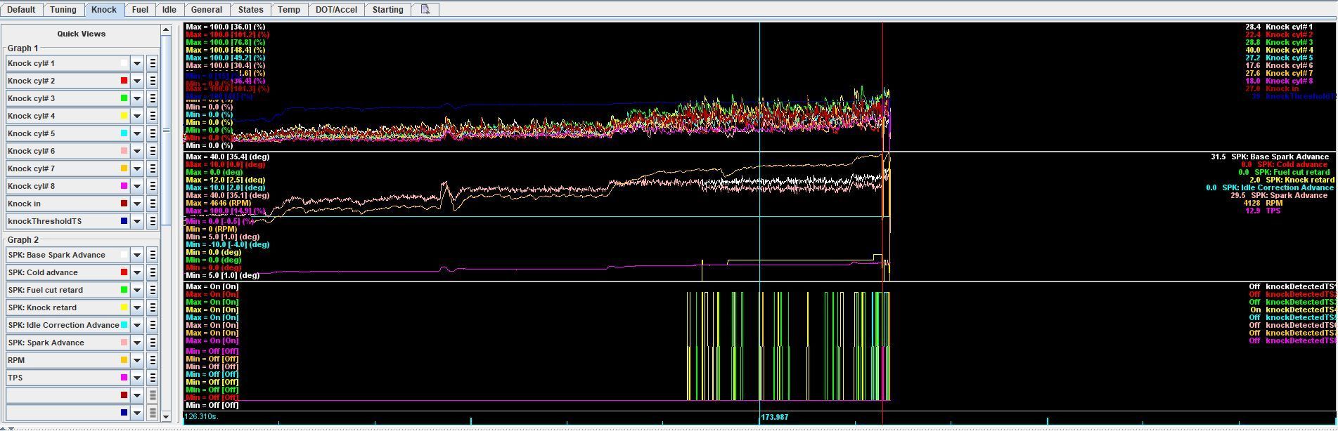
Below is a screenshot from MegaLogViewer. The top graph has the knock signals for each individual cylinder. The blue line just above them is the knock threshold. The second graph has the spark advance data, including any knock retard being applied, and RPM. The bottom graph is the on/off flags for individual cylinders when knock is "detected".
This log is only part way through my tuning so that you can see what happens when the knock signal passes the threshold (above which the ECU believes the engine is knocking). You can see the peaks in the bottom graph. After a cylinder has two events close enough together, the spark retard kicks in, which is the flat yellow line toward the bottom of the middle graph.
The vertical light blue line is a marker to show what time is selected, which populates the fields to the right with the actual point in time measurements.
These are not real knock events, just normal noise from raising the RPM with the car at rest (no load). The graph shows that the knock threshold needs to be raised at that RPM range. And it can probably be lowered a little in the lower RPM range.
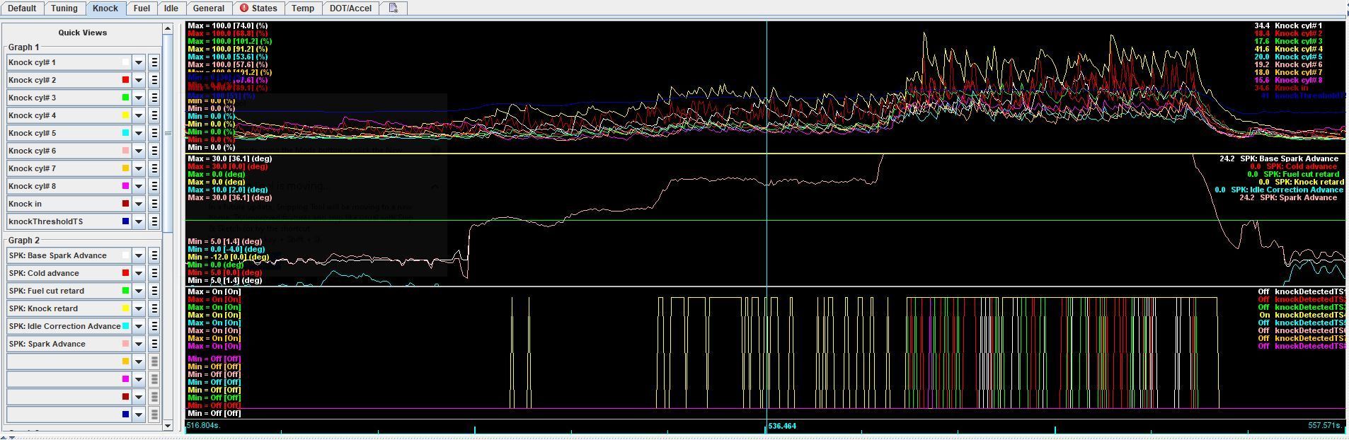
This is what real knock looks like. This is from a 911 engine with cylinder 2 (red line in the lower graph) clearly knocking in the view shown in this screenshot. Notice how much higher it is than the other cylinders? Particularly obvious in the third of the four "humps" as the operator gently increases and lowers the RPMs (white line in upper graph).
Here are my personal notes on basic setup of knock sensing. Obviously, knock will destroy a motor, so it's critical that you don't rely on the ECU's knock detection unless you're personally certain that it's configured properly. Use a detcan or other reliable knock detection tool to confirm settings.
Alarmists will tell you that the only way to configure knock detection is to induce knock and literally destroy motors, using the recorded data to establish the right settings. They will claim that manufacturers do that for OEM motors and ECU's and without that destructive testing you cannot have functional knock sensing.
I say that to go ahead and get that out of the way for those people who disparage aftermarket knock sensing. There, it's been said. So, moving on...
These are just starting points. Do not rely on them for your setup. A few comments on the settings:
Frequency: Some engines detect knock better at the second order of the calculated knock frequency, and some detect it better just above or below the calculated knock frequency. The formula I provide will calculate the theoretical ringing frequency of the cylinders. This is the standard formula used by all aftermarket knock detection strategies. The best and most certain way to determine the right frequency is with an oscilloscope monitoring a knock sensor on a running engine. This is how you can determine if the second order will give you a cleaner signal.
Integrator: Think of it like an averaging of the signal. The integrator can give you too many false high spikes if it's too low, or flatten out the signal so much that you don't detect real knock if it's too high. The formula that I've provided will provide one average per firing of the cylinder. For those who like data and instant knock response, it's a good starting point. For those who want an average over multiple cylinder firings, you'll want a higher number.
Gain: Controls how "loud" the signal is from each cylinder. Ideally, you want the averages from all cylinders to be the same. Think of it like a multiplier for the signal. A low multiplier keeps the signal within limits, but also reduces the actual amount by which real knock raises the noise level. Too little gain and real knocks won't jump up high enough on the signal to differentiate them from background noise. Too much gain and background noise will be too close to the maximum detection limit of the knock signal processor to be able to see when real knocks occur because everything will be close to the limit.
Anyway, onto my notes. Again, just starting points, don't just plug this stuff in and forget it. You need to analyze the logs, use all tools available to you, and do your best to get this right. Or, get help with it.
Set gain so idle readings are between 5% and 10%. Ideally, maximum signal at max load/rpm is under 40%. Find the best balance.
Knock frequency: 1800/(Pi * bore diameter in mm) OR 573 / bore diameter in mm
e.g. 1987 928 S4 bore diameter is 100mm: 573/100 = 5.73Hz
Real knock should present as at least double of the non-knocking signal average (usually a 4x or more multiple).
Moderate spikes above the average are not real knock.
Set the threshold so that either:
1) It is just far enough above the moderate spikes so that they will not trigger knock detection.
2) It is far enough above the average so that the moderate spikes only occasionally pass the threshold and configure knock retard to require at least 2 knock events to activate retard.
For an example of what things look like without proper gain (compare to earlier graph that I posted). It's noisy, peaky, none of the cylinders match each other. and the peaks are way too high during zero knock:
There is a tool for creating a base ignition map, but I found it to be pretty far off from the 928's base maps. In case you want to play around with it and see what it looks like: http://useasydocs.com/theory/spktable.htm
The fuel side is relatively easy with modern ECU's. Even easier if you go with MAF, but speed density will also work just fine.
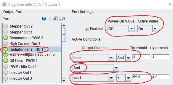
Here's an example of using various triggers and logic to control a device. There are also PWM tables for controlling variable speed fans/pumps/etc.
This is how I control the radiator fans:
1) Start with the fans off when the ECU first powers up. It goes active when both the speed (vss) is below 60mph AND a second set of logic tests are positive (loop 3, which is bitwise loop 4 in the screenshot):
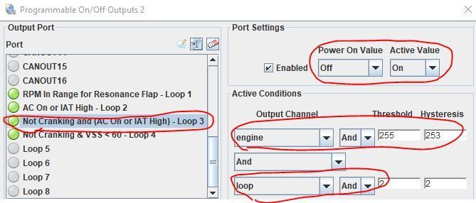
2) Loop 3 (bitwise 4) goes active if the engine is not cranking (that's what the bitwise 255/253 filter does) AND loop 2 (bitwise 2) is active:
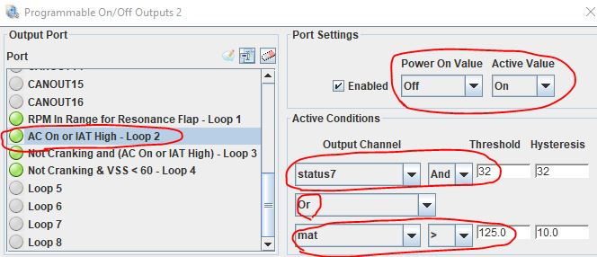
3) Loop 2 (bitwise 2) goes active if the AC is on (status 7:32) OR the intake air temperature (MAT) is high:
My radiator fans are also triggered by a separate temperature sensor on the radiator. So, I end up with the following logic:
Fans go on if:
1) Radiator fluid temperatures are "high".
OR
2) The following conditions are met:
a) Speed is below 60mph (no need to run the fans when on the highway)
b) Engine is not cranking
c) Either the AC is on OR the intake air temperatures are "high"
Just an example of what you can accomplish with the programmable outputs. Including control of the resonance flap, fuel tank vent valve, etc.
The resistor that I specify in the spreadsheet to go between the CPS +/- wires is incorrect. It's what's recommended by AMPEFI, "experts" on the MegaSquirt forum, etc. But,obviously, never tested with an MS3Pro on a 928 with stock CPS. Without the resistor, you can only hit about 1,200 to 1,500 RPM before the ECU loses the signal from the CPS. With the 10k resistor, I was easily revving past 4k, so I figured it was good to go. When I went to do knock data collection, I found it was only able to rev to about 5k RPM.
Thankfully, I had the foresight to wire in a socket and pig tail so it would be very easy for me to swap out resistors. I recommend that you do the same.
I swapped in a 50k potentiometer and changed the resistance until I found one that worked. 220 Ohms was the ticket. Wired a 220 Ohm resistor into a plug, plugged that into the socket, and it revs to redline with no problem.
Bottom line, wire in a socket with enough length to conveniently reach it, you can try a 220 Ohm resistor to start, but be prepared to swap in a potentiometer to find the right setting. A 1/4 watt resistor is sufficient, but I went with 1/2 watt to be on the safe side.
I converted my '82 928s to full EFI with a Microsquirt and EDIS-8. I went the EDIS route simply because I used the same system on my Fiat race car with a Microsquirt. Converting from mechanical injection to electronic was a revelation. I used the computor-generated timing table as per your links and left it as it was. I did all my tuning using Tunerstudio auto analyse and recently upgraded Megalogviewer to the HD version. What I did find was the standard power supply from the switchboard was totally unacceptable for a modern ECU. The 928's basic layout allows spikes into the system from the alternator. I run separate power and negative cables directly from the battery to the ECU fuse/relay panel and the earth to the earth bar on the engine. I also switched all the sensors to GM products. There are no crankcase fumes in the intake which also makes a massive improvement. I run speed density.

 08-09-2022, 10:18 PM