When you click on links to various merchants on this site and make a purchase, this can result in this site earning a commission. Affiliate programs and affiliations include, but are not limited to, the eBay Partner Network.
It's not really "cruise referenced". The earlier cars are using the reed switch in the differential. The cruise happens to be one of the consumers of that input, as is the speedometer. And a very convenient place to acquire that signal for an aftermarket ECU is where the wire goes into the cruise control. Easily accessible from the passenger foot well. And universally applicable for both the earlier and later cars, regardless of what generates the pulse.
Using the ABS tone rings is also equally possible for the earlier cars and will enable traction control functionality if you get at least one from each axle. But, you have to make sure that you create an appropriate circuit so as not to interrupt the ABS computer's functionality. Just connecting into the wire without any other isolating components will cause problems for the ABS computer and it won't work properly. Presumably, the FCU has this built into it, which the WSM wiring diagram implies with a simplified view of the circuit inside of the FCU. You'll need to replicate that. Very doable and well documented, but it must be addressed properly.
If all you want is vehicle speed, then using the 8 pulse line is more than sufficient and easy to use. If you want traction control, then you definitely want more than 8 pulses per wheel revolution and you need at least two speed inputs (one per axle), but preferably all four to do it right. Using dedicated sensors would be the "safest" way to do it, preferably hall sensors, but sharing the ABS tone ring sensors is possible if the wiring is engineered right.
Yep, JBperf is the go to for a lot of megasquirt i/o.
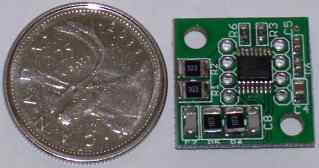
But, that board is for taking vr signals and converting them to a square wave. The MS3Pro already has VR conditioners, so that extra board isn't needed. And the board does not address isolation for sharing a VR sensor with an ABS computer.
That's a good find. A bit pricey for something you should be able to build yourself for a tenth of that price, but it's a really nice package.
The only way to find out if the ABS computer can share the VR sensor is to try it. Including testing and activation of the ABS system at all wheel speeds. Short of that, it might work at some speeds and not others. Or, your VSS input might be the one to suffer the outages. Or, it might all work perfectly without an issue.
Which is why I said the "safe" way is to add a sensor. Preferably a hall sensor so that you don't have to worry about signal conditioning, just shielding.
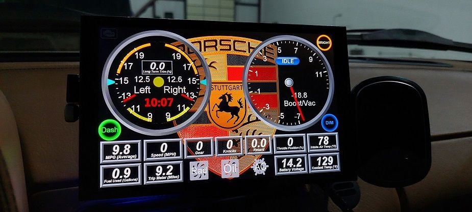
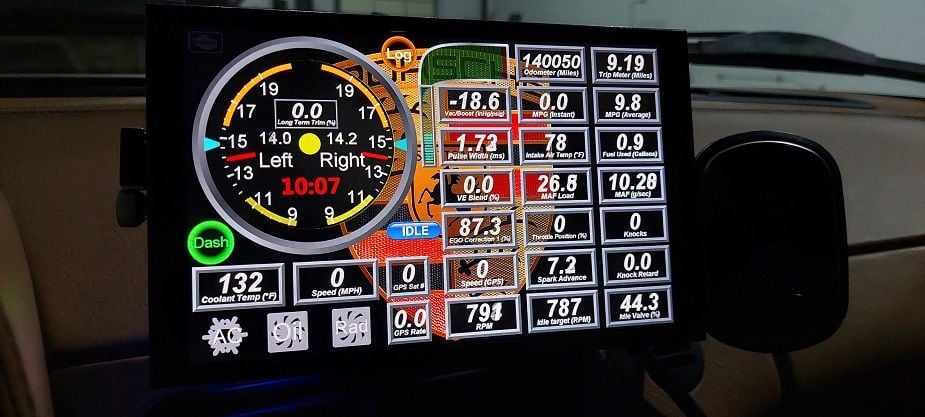
You my have noticed that the AFR's on the two screens above look a little off. On the main one, with the CLT at 129, it's really rich. On the extra dash the CLT is 132 and AFR's are closer to stoich.
What's going on here is that I have zero warm up enrichment (WUE) added. If I add negative WUE, removing fuel, to get a more reasonable AFR during warmup, it causes a problem with warm restarts. After the motor is fully warmed up, if I let it sit for an hour or two and then restart it, the AFR's will be much leaner. Closer to the target AFR.
I have EGO correction (closed loop) set to come on at 130 CLT. So on the "extra" dash, you can see that the coolant has reached 132 and the ECU is bringing the AFR's up toward stoich. And you can see that the EGO correction is at 87%. That means 87% of the originally calculated fuel to hit the AFR target. In other words, it's removing 13% of the originally calculated fuel. Once the motor, intake and heads are fully warmed up, that will be at 100%, meaning no correction at all.
So, the coolant temperature is not an adequate indication of the overall VE of the engine, and I believe it's related to the heat soak of the intake manifold and heads.
To address this and use closed loop to hit specific targets regardless of the VE, Megasquirt does have the ability to blended AFR tables to provide a smooth transition. But, it can't be based off of the coolant input. At least, not by design. It only accepts analog inputs like TPS, MAP, and a few other things as variables for the X-axis.
I'm ok with the rich AFR's during initial warmup. It's richer than I would like, but not worth fiddling with to try to determine a reasonable balance between having it a bit leaner during warmup but not too lean for a warm restart.
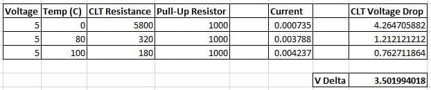
But, I did come up with a solution to achieve CLT based AFR targets. And it's doable because of the dual element coolant sensor on the 928. Right now, I have just one side of the coolant sensor hooked up to the ECU. Leaving the second one free. If the second one is connect with a pullup resistor to a 5v reference, it could be used as a standard analog input in MegaSquirt, which can be used in the AFR blend table. Effectively enabling coolant temperature based AFR targets. I've calculated that a 1k pullup resistor will give the biggest range/resolution:
Eventually, I may add this function. For now, it hasn't been an issue. If someone goes a similar route, it may be worth wiring this in from the start so you at least have the option should you want to make use of it at some point.
A fairly significant update. I enabled table switching so that both MAF and SD VE tunes have 32 rows available. Rescaled them with the appropriate overlap. Also, pulled fueling out of the ASE curve for colder temperatures. Minor update to the IAC PW target value table.
The latest VSS setup is working well. I can now just change the tire size in the ECU when I switch between winter and summer tires, and the MPH stays accurate.
Minor revisions. The SD VE maps are smoother and more realistic, with about as much autotuning done as I plan to do.
The car drives immensely better than it did stock. Ignoring the power gains, it's super smooth now. Even at very low speed and very low RPMs with it in gear (this is a manual transmission), for instance at parking lot speeds, it is so smooth that you would mistake it for an automatic. Just the ECU upgrade alone is worth it.
Another minor update. I changed the lag factor on the MAF signal to smooth out the signal for a smoother idle. It was already very good, now it's even better.
Concerned that slowing down the signal might affect responsiveness and acceleration enrichment, I played with those a lot. What I found is that any AE at all, even just 20% for 4 ignition events, is too much. No matter how little I tried to apply, it just doesn't want any AE at all. Responsiveness remains unchanged from what I feel from the driver's seat and from what I see in the logs.
I'll start posting the ancillary stuff next. Like dashboards, custom channels, logos, etc.
The attached zip file has images that I've used (background and Windows boot splash mostly), the custom channels and persistent channel configurations, aliases for inputs, the dashboards, and the script for managing the PC/monitor power.
If you want the full project folder, send me a private message.
Updated the ignition tables to use the secondary load ignition tables as an extension of the primary tables. Giving me an effective 32x32 table for more resolution. Used the table blending curve to make that happen. Updated tune attached.
Also attached is a spreadsheet that calculates the effect of the lag factors. It includes a graph to help visualize it. I've also included some data on various inputs and sensors with their update rate and response time. This will help anyone who's trying to determine the best starting point for input averaging to find a value that provides the best smoothing with the least impact on responsiveness.
As an example, the MAF input has an update rate of 7.8Khz with a response time of 40ms. Using a lag factor of 20 (20% of value difference allowed with each input cycle), it only adds 2.5ms to time it takes for the smoothed MAF value to reach 99% of the actual raw value. Which is only 6.5% of the 40ms response time, so it's a negligible effect on engine responsiveness while having a large impact on smoothing.
At the other end of the spectrum is the CAN based WBO2 sensor. At 100Hz update rate and 20ms response time creates a 200ms delay to reach 99% of the raw value. With a response time of 20ms, that adds 1,000% to the response time, creating a huge impact on close loop AFR management.
Anyway, for those that come after me, hopefully this will help in building a tune.
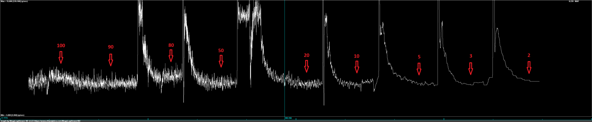
Did some testing with the MAF input. The 7.8kHz update rate requires a very low lag factor (lots of smoothing) to have any effect. The below graph shows how each lag factor affects smoothing. The spikes are throttle blips that I used to help me identify where I changed the lag factor. Otherwise, it's all at idle RPMs.
I did further tests with throttle input changes to log and analyze the degree of impact the various lag factors had on MAF response times. I found that a lag factor of 7 is just right for my setup.
With all of the response time testing, it becomes very clear that the MAF responds much faster than the MAP sensor. Even with the heavy smoothing that I've applied to the MAF input, it's still faster than the unsmoothed MAP input (speed density).
I also found that the spreadsheet was pretty much dead on with determining the effect of the lag factor on full "catchup" to a new value.
The lesson here is that you need to factor in the update rate before setting a lag factor. And then you need to do some logging to compare your subjective observations against the objective data.
The MAF smoothing made a tremendous difference. It's smoother in all types of driving, including with the throttle plate barely cracked open. I no longer need to blend in the SD tune, so I repurposed those maps for MAFload, giving me 32x32 resolution to match the 32x32 for ignition.
It's just starting to get colder here, but still not below 65 in the garage yet. Maybe this coming week I can finally do some cold start tuning in the 40's.
Latest tune attached. Other than sub-60 cold start tuning, it's good to go. I am sure that I'll continue to tinker in my free time, but I'm going to be focusing on other projects.
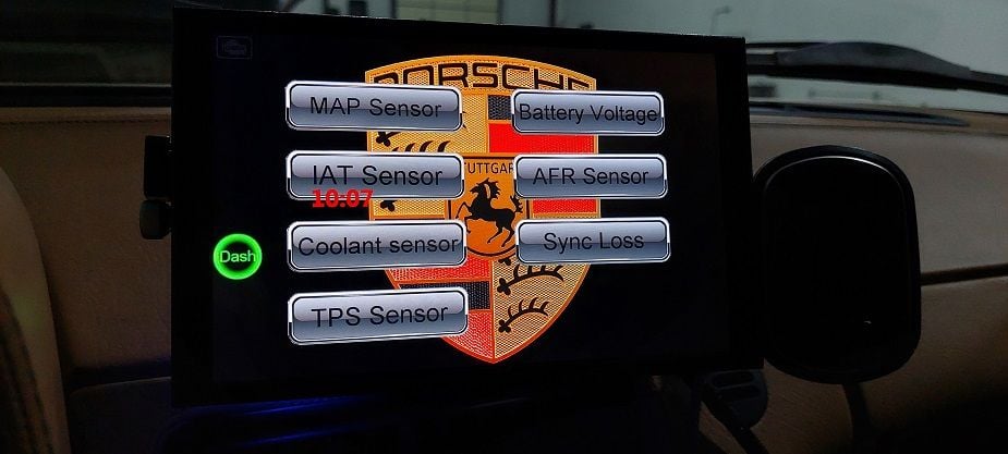
I've been playing around with some dashboards. Lots of possibilities. It's a magnetic mount so it only takes a second to stow it.
I have been working with Nick Pahls who owns Pahls Performance https://pahlsperformance.com/ and Raspberry Pi Dashboardshttps://pidashs.com/ on a ultra wide touchscreen setup for my 928. The plan is to put the screen behind the pod opening and replace the OEM cluster. Nick also is a Megasquirt Dealer so maybe this would be a clean way to tie in your data from your Megasquirt on your 928. My 928 has an engine swap and I was also looking at using Megasquirt with it and to tie it into the dash display information. They can setup multiple screen options that you can just swipe the screen to get different modes like normal driving mode, track, race, or just different looks, etc.

 10-10-2022, 03:12 PM