When you click on links to various merchants on this site and make a purchase, this can result in this site earning a commission. Affiliate programs and affiliations include, but are not limited to, the eBay Partner Network.
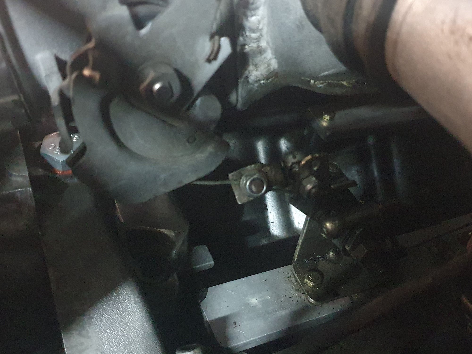
This is my throttle setup. In the big hole left by the removal of the CIS stuff, I have an aluminium frame. On the rear of the frame is the earth bar for everything and the coil packs are bolted there. Up the front where the original throttle lever was is the original throttle with the cables for the throttle and the auto gear change. The flexible cable from the throttle body just attaches to the original throttle lever, the TPS is on the other side. The gearbox cable needed a small amount of setting up to get the perfect change points.
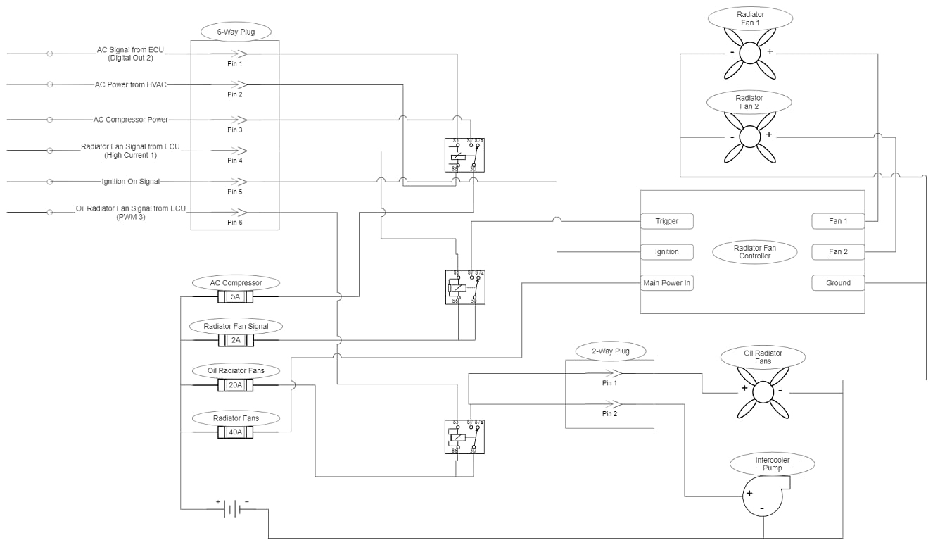
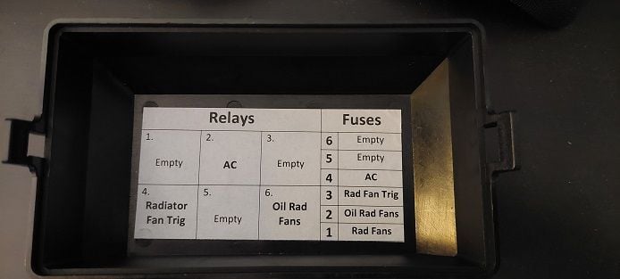
I finally got around to installing the relay box that I had built. This does a few things:
1) Let's the ECU control whether or not the AC compressor is on, so I can shut it off when at WOT.
2) Moves the AC Compressor load off of the HVAC head unit and to a dedicated relay.
3) Lets the ECU control the oil radiator fans and intercooler pump.
4) Lets the ECU trigger the radiator fans:
a) To help cool down the intercooler heat exchanger when needed
b) To turn off the radiator fans when AC is on at highway speeds
The radiator fan controller still controls the fans to manage radiator temperatures.
Latest revision. More refinements on the priming and cranking pulses, some axis scale changes on the VE and ignition maps, VE map smoothing, some overrun specific ignition timing, closed loop idle adjustments, closed loop EGO/AFR adjustments, AFR target map changes, more advanced timing in the boost cells, reduced the smoothing/lag on WBO2/IAT/Coolant/MAF sensors, VSS smoothing increase.
Something interesting is that TunerStudio has the ability to load "partial" tunes. Which can be any subset of a full tune. Down to just one single item or value. I'm using this feature to give me manual control of the radiator fans. The radiator fans pull air through the intercooler heat exchanger, so I wanted to be able to turn them on before a pull to see if that makes a difference in the peak intake temperatures. But, you could also use that for things like a higher boost profile, or retarded timing, or even a full fuel system disable as an anti-theft measure. Whatever you could want.
I had the car out a couple of days ago and the car is such a pleasure to drive. A huge transformation from the SharkTuner. Much much more responsive, smoother transitions, super smooth idle, it's just great. Completely worth it.
And the new PC driven dashboard is outstanding. Massive improvement over the Android version, which was already far ahead of traditional analog gauges.
1) Idle valve target duty cycle map and close/dashpot-adder updates. Especially to work around a firmware bug that opens the idle valve by the AC adder when not idling.
2) Blended MAF/SD VE tables to handle a very light load zone that has air flow reversion.
4) I narrowed the knock window down and made a few adjustments to gain and thresholds. It's very dialed in now and I fully trust it.
5) Ignition map is advanced a bit in the cells that see boost and I'm working on smoothing the transition from NA to boost now that knock sensing is set.
A bunch of other minor updates.
An interesting thing to note: My TPS was previously very jittery when fully closed. Even during bench testing it would fluctuate by up to 2%. Until it got warmed up, and then it would be rock solid. I tuned around this initially, but it's now rock steady all the time, not just when warmed up. I can only attribute this to it needing to be broken in a bit. I don't think this is normal, but it's worth bench testing the TPS prior to installation. Mine was a brand new Bosch TPS, nothing untoward about it or its source.
Now for the pretty pictures
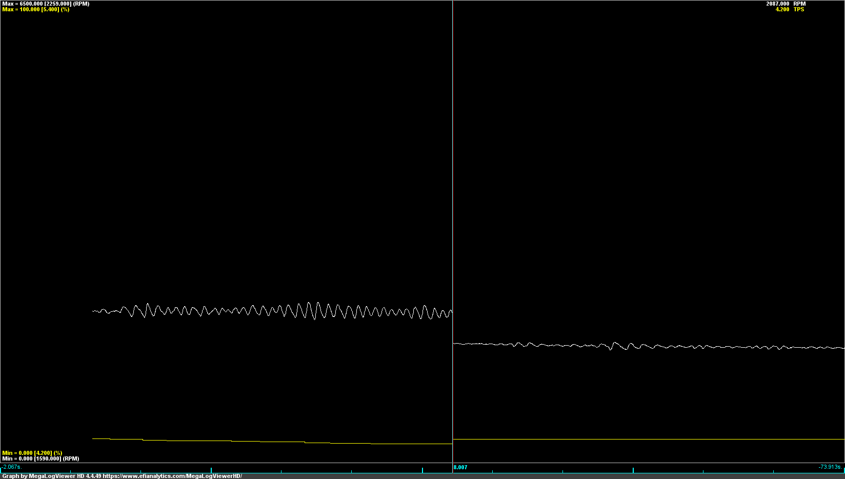
Below is a graph showing RPM (white) and TPS (yellow). The vertical line separates the before and after, about 8 seconds on either side. Both before and after are from similar loads and vehicle speeds. The only difference between the two is with the idle valve cracked open in the "before", due to the firmware bug, and fully closed in the "after". It's still not perfect in the after, but much much better. I further improved this by rescaling the VE map to give more resolution in this zone and fine tuning the VE values there. The SD blend should finish smoothing it out.
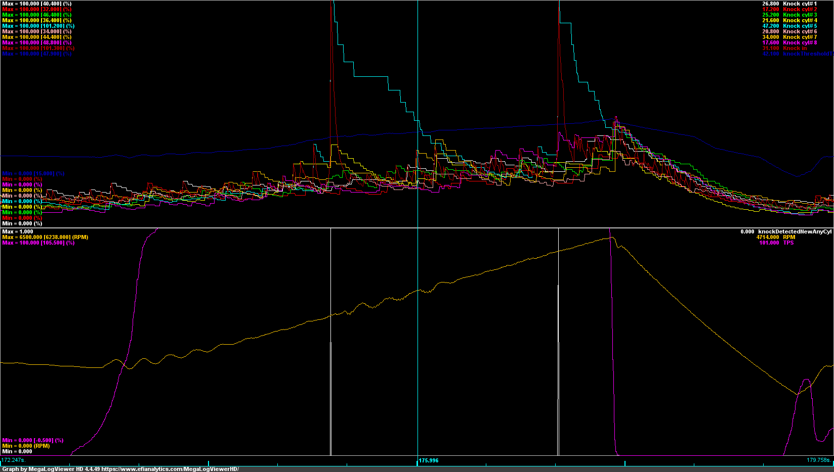
And here is a WOT run where two knocks were detected. Upper graph has the knock signals (red spikes are knock, blue line is knock threshold). Same cylinder (5), very different load and rpms. The white lines are when the knock was detected. The yellow line is RPM, and the waves are wheel spin.
Bumped the blend up to 100% for the target zone, completely resolved the issue. I need to do more driving to dial in the VE for SD, but it's pretty close at this point.
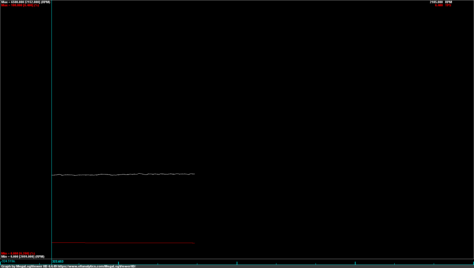
Here's what the similar RPMs and throttle position look like now with the blend applied:
I narrowed the 100% portion of the SD zone and stretched out the blend zones on either side to provide a smoother transition. Then I let autotune do its thing for the portions of the SD map that I'm using. The results are really good. Very smooth transitions now with target AFR's being hit. Without affecting all of the benefits of MAF for the rest of the map.
Despite TunerStudio allowing you to turn autotune on for two different VE maps at the same time, don't do it if they overlap. As I learned the hard way, they will not reach an equilibrium in the blended zone. They will either oscillate their changes back and forth or eventually max each other out. One at a time works fine, though. Even better to do them without blending first.
I also changed from using coolant temperatures as the Y axis for idle valve target duty cycles to using intake air temperatures. CLT worked, but it wasn't as dead on as I would like. Using IAT's the idle now hits the target almost perfectly when putting the clutch in or revving it.
I've spent some time on the calibrations of the MAP and barometric pressure sensors. It turns out that the MAP sensor (MPXH6400), which is a very common one in use in many aftermarket ECU's and generally considered very good, has a +/- error of 5.5kPa. Which doesn't matter a whole lot for SD or general tuning. But it can be confusing if you're looking at the logs and anticipating greater precision. It's just something to be aware of but not a problem.
At this point, the tune is done. I'll still need to dial in cold start tuning in the colder temperatures, and I do plan to see how far I can push the timing in the boost cells when I'm looking to tinker, but otherwise it's done.
I ran into no significant issues with the installation. Bench testing everything, prior to installation, paid major dividends. Everything worked. And worked the first time. It even started right up on the very first attempt. Everything from there has just been fine tuning. It was drivable from the first start.
I'll get some shots of the views that I have setup on my touch screen, which replace my old analog AFR and boost gauges. I'm super happy with the layouts and information, but they are 100% customizable to whatever you want.
Excuse me for not reading the whle thread, perhaps my question was covered somewhere.
Question: Where did you put the computer and what location did you choose for the cables to run through the bulkhead?
In my case, the Microsquirt is behind the fuse panel at the top, relay board sits on the parcel shelf under a leather cover. Sensor wires pass through the existing holes in the bulkhead. The only hole I drilled was for the O2 sensor cable through the floor.
Using the tool, you can set the receiver up to for a 10Hz rate, only export NMEA data, and set it for a higher baud rate. With those changes, you get a consistent 10 position/speed updates per second. All for a very inexpensive price.
I've plugged this into my on-board computer and configured TunerStudio to use the GPS signal for power and torque calculations. It can also use it for MPG, trip meter and odometer, but I prefer to rely on the OEM VSS for those functions. TunerStudio logs the position and speed updates along with its regular log channels.
TunerStudio does not feed the GPS data back into the ECU, so it can't be used for speed based configurations in the ECU like how I have the radiator fans shut down at highway speeds. To feed GPS data into the ECU, I would go with one of these:
It was bothering me that the VSS was so inaccurate without such a large sampling window (0.5 seconds). Fluctuations are one thing, but inaccuracy shouldn't be present. So, I added a pull-up resistor between the VSS signal line and a 5v reference signal. Now, it's accurate with any sampling window. There are fluctuations if the window is too small, but it's no longer inaccurate if the sampling window is small.
I used one of the unused 5v reference lines on the MegaSquirt ECU and connected it to a 2k Ohm resistor. That resistor was then connected to the VSS signal line. One end of which goes to the OEM reed switch by way of the cruise control unit and the other end is connected to a frequency input on the ECU.
So, for anyone that follows, do this from the start when you do the initial wiring of the VSS.
I switched the on-board PC shutdown process to hibernate. These are the startup times that I've been getting from key off and on-board computer fully powered off ....... to key on and full instrumentation online:
I reworked the script a bit, shuffling the TunerStudio application graceful shutdown code off to a function that can be called as needed. There is also error handling for the hibernate. If it fails, the script will gracefully shutdown TunerStudio so no data is lost, and then shut the computer down.
It was bothering me that the VSS was so inaccurate without such a large sampling window (0.5 seconds). Fluctuations are one thing, but inaccuracy shouldn't be present. So, I added a pull-up resistor between the VSS signal line and a 5v reference signal. Now, it's accurate with any sampling window. There are fluctuations if the window is too small, but it's no longer inaccurate if the sampling window is small.
I used one of the unused 5v reference lines on the MegaSquirt ECU and connected it to a 2k Ohm resistor. That resistor was then connected to the VSS signal line. One end of which goes to the OEM reed switch by way of the cruise control unit and the other end is connected to a frequency input on the ECU.
So, for anyone that follows, do this from the start when you do the initial wiring of the VSS.
Out of curiosity, did this have any effect on the 928 factory cruise system? I will have to give this a try. Thanks for the interesting data point.
No effect on cruise control or speedometer. Those were the first things that I tested.
A later model that has a speedometer generated pulse might not need the pullup resistor if the pulse swings high when not grounded. Worth checking first.
For those playing along with this cruise referenced speed output:
Up to 1990, the speed reference came from the transmission. All those senders and the electronics were designed to reference 8-pulses/revolution.
Starting in 1991, the trans mounted speed sender was removed in favor of using the ABS/PSD signals originating from the front left wheel tone-ring. This output is 45-pulses/revolution.
To keep from redesigning the instrument cluster and cruise control module, the 45-pulse signal is transformed in the FCU (CE socket XIX) back to am 8-pulse/rev signal.
So, on 91+ cars, there may be an opportunity to get the higher resolution signal from "Pin R" on the FCU. "Pin T" has the decimated 8-pulse output heading to the cluster and cruise.

 09-08-2022, 09:47 PM