When you click on links to various merchants on this site and make a purchase, this can result in this site earning a commission. Affiliate programs and affiliations include, but are not limited to, the eBay Partner Network.
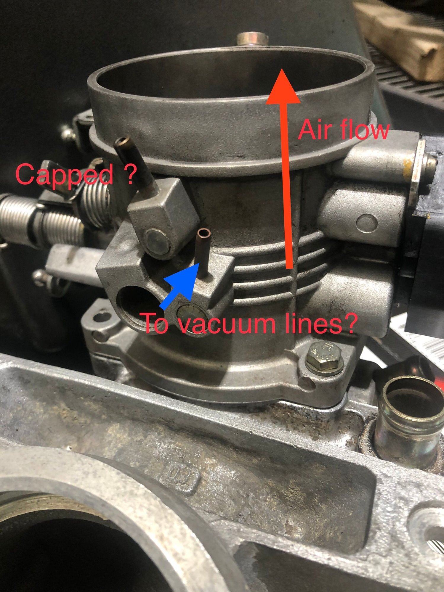
Upstream means relative to the direction of airflow- downstream the opposite. Thus the port you have labelled "vacuum lines" is correct but it is the downstream port given the system needs to measure what is going on between the throttle butterfly and the inlet tracts unless of course there is some weird porting in the throttle body that I am not aware of [highly unlikely].
Not sure about your model year but the upstream port on the later models is connected to the pollution control system on the fuel tank vent system as I recall.
Upstream means relative to the direction of airflow- downstream the opposite. Thus the port you have labelled "vacuum lines" is correct but it is the downstream port given the system needs to measure what is going on between the throttle butterfly and the inlet tracts unless of course there is some weird porting in the throttle body that I am not aware of [highly unlikely]..
Thanks Fred, could you confirm you are saying the vacuum lines to the pressure regulators etc should be off the other port that I have labelled capped? (I would have thought that also but it has been connected on the other port on the air cleaner side of the butterfly since I have had the car?)
Thanks Simon also for your diagram, it help clears up somethings, however I think this must be for the later 32V engine, I don't have the 10: Vacuum distributor, and I believe my line to auto trans comes from the front of the intake manifold ("spider").
If the throttle body picture is accurate (ports position) it also suggest the yellow "vacuum" lines come off the opposite port to mine!
PS Mine is 1985 16V (RHD AUS not that it would make much of a diff)
I believe you are correct that the US from a 32V, but I think it is an 85 US model, so the vacuum diagram should be very similar to the 85 16V. The distributor may be made up of more individual Tees or Ys to form the branches, but should function basically the same.
Have you by any chance looked at the under side of your hood? From the factory it would have originally had a sticker with the diagram on it.
Thanks Fred, could you confirm you are saying the vacuum lines to the pressure regulators etc should be off the other port that I have labelld capped? (I would have thought that also but it has been connected on the other port on the air cleaner side of the butterfly since I have had the car?)
Hi,
I was trying to say that logic suggests that the vacuum lines to the regulators and tranny modulator have to be taken from the port marked "capped" or equivalent as they need to be driven by the vacuum status between the butterfly and the inlet plenum but somehow my logic last night was "fuzzy" probably because i was just about to turn in and what I actually wrote was unintentionally inverted relative to what I was trying to articulate - sincere apologies.
The layout suggests that the downstream nozzle will be the one that you report as being "capped"- easy enough to blow some air through it to test itis ported correctly- that or check the idle vacuum that should read about 18 inches Hg or so when fully warmed up. Not sure what would happen if they were transposed - was the fuelling over rich at idle and low load by any chance? If they were the wrong way round logic says there would be little to no impact at full throttle but then I only have one cup of weak coffee in me at the moment!
There is a diagram in the WSM for the 84 model year throttle body that appears to line up with that logic but the diagram that I presume is for your model year [1985] is just not clear and I have no idea if they are one and the same thing physically.
Hopefully some kind soul will confirm the above is correct now that we have stimulated some discussion. The other diagram does indeed look like the one in the manual for the early 32 valve models that were [exclusively?] imported to the States 1985 on.
The distributor may be made up of more individual Tees or Ys to form the branches, but should function basically the same.
Have you by any chance looked at the under side of your hood? From the factory it would have originally had a sticker with the diagram on it.
Thanks Simon, yes look like mine has series of Y's which must have later been replaced by the distributor, but I can't recall seeing a thermo switch or shift valve. Unfortunately I don't have a diagram on the underside of hood.
PS What valve is this one: ?
Hi,
There is a diagram in the WSM for the 84 model year throttle body that appears to line up with that logic but the diagram that I presume is for your model year [1985] is just not clear and I have no idea if they are one and the same thing physically..
Thanks Fred, I believe the 84-85 models with the M28.22 (16V LH injection) engine are referred to as Euro, the 84 model diagram may be what I am after. Where do you get access to the WSM ? thanks
Thanks Fred, I believe the 84-85 models with the M28.22 (16V LH injection) engine are referred to as Euro, the 84 model diagram may be what I am after. Where do you get access to the WSM ? thanks
I get access in the Cat's room [that is where I keep my WSM volumes-]
The following images are for the fuel damper and air management circuits. Maybe you can relate to them. Does your model year have the auxiiary air valve [item 9].

 08-05-2022, 08:56 AM


 ]
]

