When you click on links to various merchants on this site and make a purchase, this can result in this site earning a commission. Affiliate programs and affiliations include, but are not limited to, the eBay Partner Network.
I have sent that off and had it overhauled a few weeks ago. Since I have that done I have now started on the the rest of the system. Of course I was hoping the the AC would work with a rebuilt head.
Dan
Putting the relay in engine compartment turns the load circuit from the CE panel to the AC into a trigger load only. That wire is old and runs along the top of the engine, which causes the current draw requirement from the climate board relay to need more current....turning it into a trigger-only signal to a 53 relay near the comp. after all tests IMHO solves the heat soak increase in needed current draw at the climate board....
FYI the increase in current draw can also burn out the freeze switch.
I never thought about how many amps an AC clutch pulled, but with the jumper post on the right putting a relay over there would be easy. will look into that. Also this is the first my mechanic has heard of high/low switch in one sender and the schematic show a low pressure switch only!
So is this the high or low pressure switch, possibly both in one unit?
I think Ken has answered your query but just in case- the item shown on your photo is the pressure transmitter - this sends a modulating signal to the brains that controls the ac system and the fan speed and has nothing to do with the compressor power circuit..
The high low switch is mounted on the lower end of the HP discharge manifold and that carries the voltage to the ac compressor solenoid. The relay in the control head is marginal size wise and is a common failure later in life as demonstrated by a tendency to mysteriously drop out when the system warms up. The common workaround is to mount an external heavy duty relay as opposed to the stock weener relay. Some folks use the stock relay circuit as a trigger for a bigger relay powered from the hot post- as you say easy to do.
Also helps to advise what model year you have as these systems can vary year to year - on the S4 series the compressor itself changed - my 90S4 had the 10PA20C compressor just like the GTS and that changed configuration some when the R134a variant was introduced mid 93 model run but the control system is pretty much the same on all S4/GTS variants as far as I am aware.
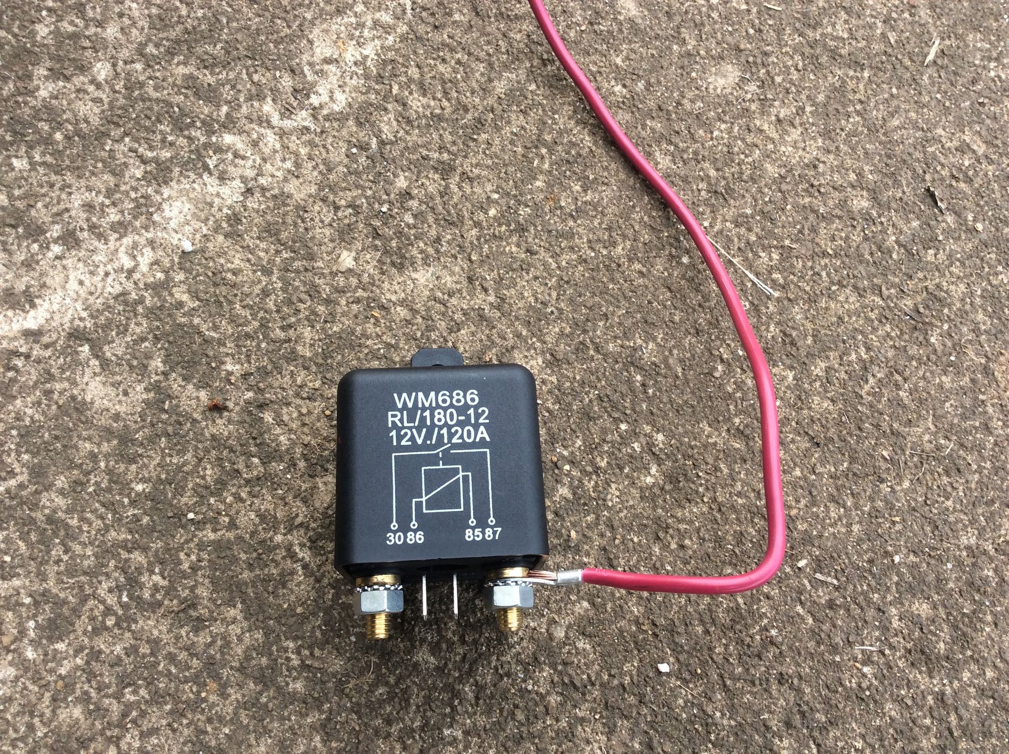
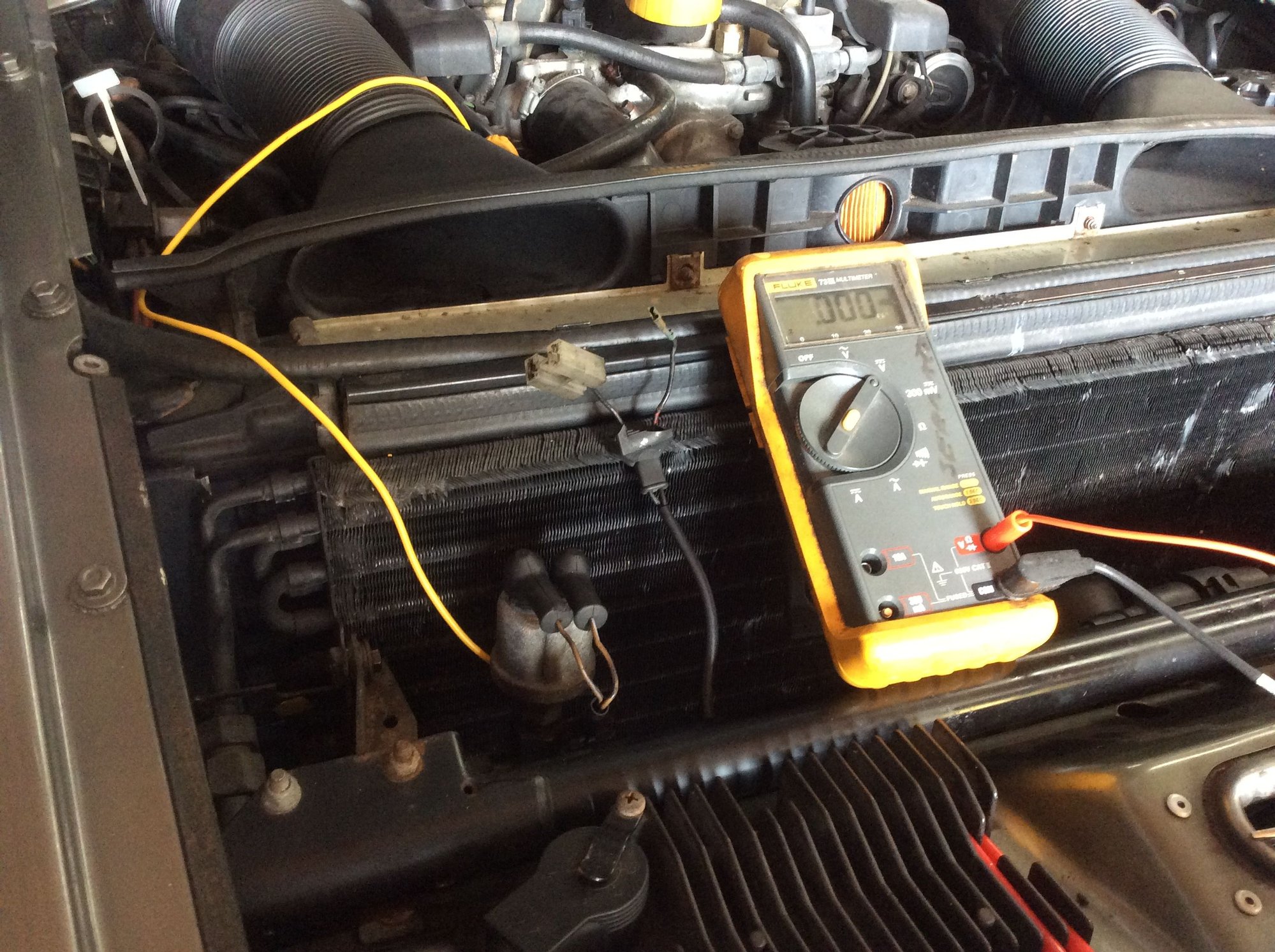
So I have power to the Hi/Low switch that sends power to the 14 pin connector and that sends power to the clutch. My wire from the H/L switch to the 14 pin connector is bad, connector to clutch wire checks good! So I got this relay and using the starter post for power to the clutch wire. Grounded the relay to the right front ground point (and cleaned it), then removed the power wire from its plug and hooked it to the H/L switch, ran a jump wire to the new relay as the trip power. So now the clutch gets big wire direct power and the AC controller in the dash just powers the relay.
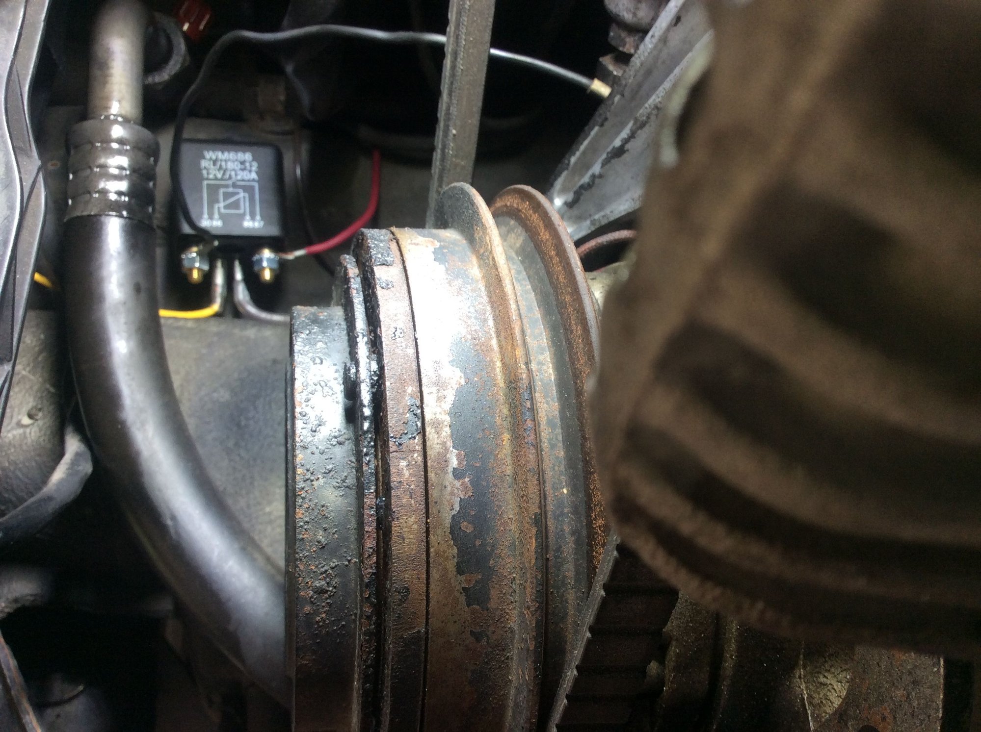
Note that the power pole on the relay will allow me to put a pusher fan on the condenser so both the clutch and fan will work together and are controlled by the dash AC unit. 120 amp with 14 gauge for jump post Freeze switch wire to H/L switch removed from plug Relay in place, can connect fan wire when fan is mounted
Note that terminal 87 on the relay is for the driven output, terminal 30 is for the power supply. If you are powering the ac compressor clutch solenoid AWG14 will be fine. However you might want to rethink what you are proposing to do if you want to power both fans from that output terminal. I suspect it makes little real world difference but may help prevent the relay from burning out prematurely perhaps?
The hot post is a junction carrying power supply to the 30 bus [permanentlylive] in the CEL. I am not sure how heavily loaded that circuit is but if it were capable of carrying power supply to both fans why did they route two separate 6mm2 cables to each fan?
When I looked into this design I figured that one day I might have an issue and want to run power to either auxiliary fans or even to the main fans if there was a problem with the wiring that might be tricky to re-run. What I reasoned was that there was plenty of capacity in the main feeder to the starter motor so when I re-worked the engine harness I ran a bigger cable [16mm2] from the starter motor to the ABS post so that I could if I ever wanted to, power up two 15 amp motors from that node.
I am not sure why Porsche put the hot post where they did but I suspect it was so that one could easily recharge the battery - not power up 30 amps worth of fans.
Well power flow from #30 to #87 is for electrical drawings but on the relay it does not matter. I had the power coming in from that side because that was best to get it to the start plug. Also that relay will drive a separate pusher fan (7 to 8 inch) that will be in front of the condenser, not the engine fans that remain on their own system. This setup will minimize the power requirements on the AC controller and help improve the condenser efficiency and I hope help the cooling in the car. It is a 120 amp relay and should handle the power fine. Dan
Well power flow from #30 to #87 is for electrical drawings but on the relay it does not matter. I had the power coming in from that side because that was best to get it to the start plug. Also that relay will drive a separate pusher fan (7 to 8 inch) that will be in front of the condenser, not the engine fans that remain on their own system. This setup will minimize the power requirements on the AC controller and help improve the condenser efficiency and I hope help the cooling in the car. It is a 120 amp relay and should handle the power fine. Dan
Dan,
Apologies - Must have misread your intent regarding fans. Even so a small fan like the one you are suggesting will [I suspect] be about as much use as a chocolate fireguard. I have such a project in mind and have a 13 inch pusher fan of the same power level as my SPAL twin fan cooler package and that draws circa 15 amps per fan. If you fit the smaller fan then the hot post cabling is probably OK for such given it will be about 5 amps load..
Regarding relays I strongly recommend that you develop the mindset discipline that wiring is not simply about dwgs. Conventions exist for a reason and whereas it is easy to understand why using a terminal a given way might make installation a bit simpler just remember that a live unfused cable is in fact a potential welding machine in the wrong hands. Your choice of course.

 08-11-2021, 07:30 PM