When you click on links to various merchants on this site and make a purchase, this can result in this site earning a commission. Affiliate programs and affiliations include, but are not limited to, the eBay Partner Network.
1980 and 1982 Instrument Cluster Wiring and basic test plans
Hi All
Updated v2 - High beam and Indicator correction
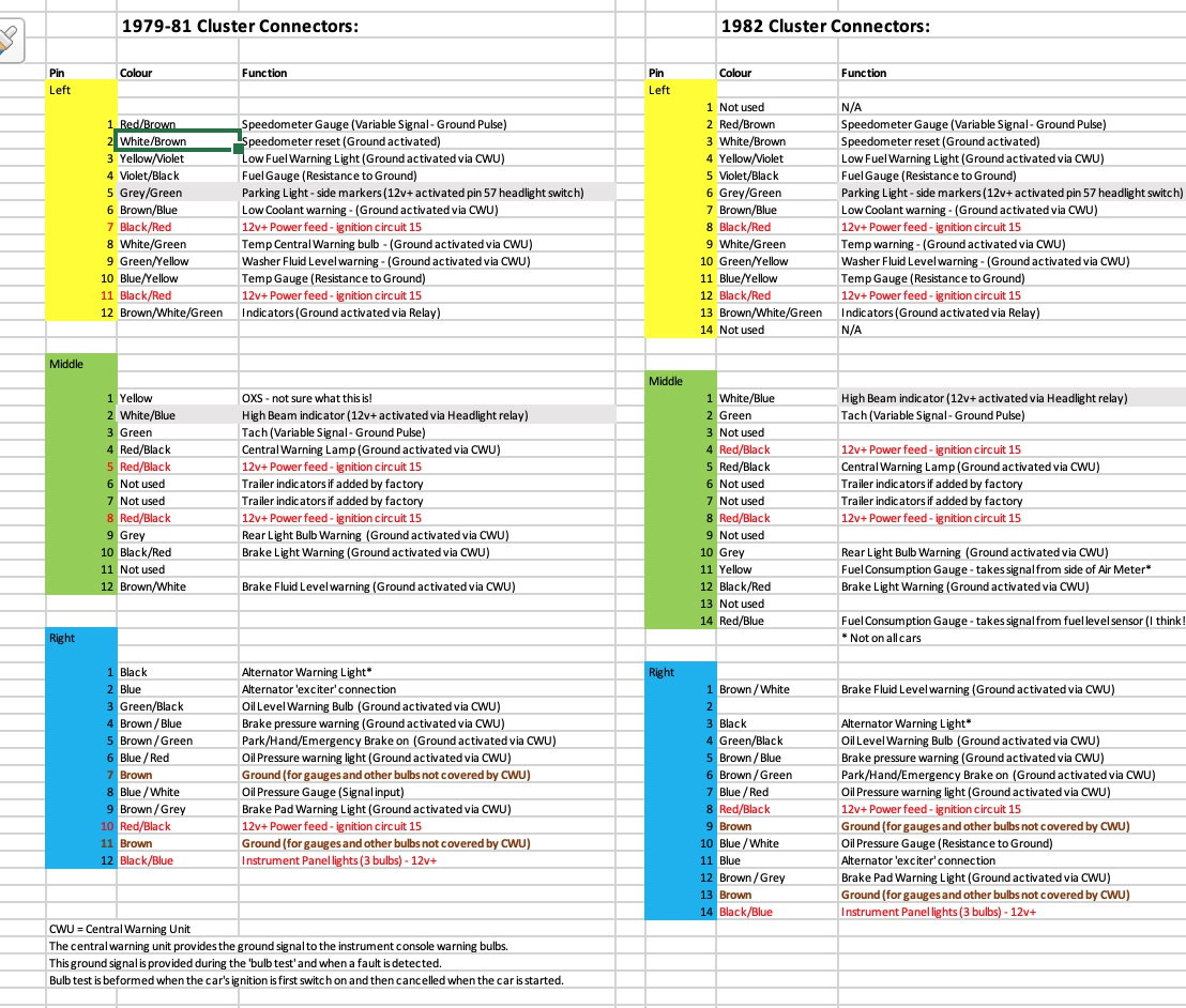
Using the wiring diagrams, and inspecting my own car, I pulled together the attached spreadsheet (two tabs) for a friend who was troubleshooting his instrument cluster. Thought i'd share them for someone else to use for troubleshooting or instrument console 'hard wire'.
I've mapped out the functions of each pin for both the 80 (includes 79 and 81?) and an 82 (82 to 84?) - for Euro's but i think are the same for US.
The tests included in the attached xls were to work out why the warning lights weren't illuminating.
I've highlighted in grey the area i'm not sure of as I've not tested on my own car.
L and R are as you are facing the instrument panel in the car.
Feedback / corrections welcome.
Last edited by Chopperharris; 06-08-2021 at 06:27 PM.
Awesome and thanks for sharing.
Are you Ok with it being added to the tech section of my web site - if not no worries.
__________________
Does it have the "Do It Yourself" manual transmission, or the superior "Fully Equipped by Porsche" Automatic Transmission? George Layton March 2014
928 Owners are ".....a secret sect of quietly assured Porsche pragmatists who in near anonymity appreciate the prodigious, easy going prowess of the 928."
This is amazingly useful (to those of us trying to work out if their cluster is broken!)
I was just going to post about using an Arduino to test the cluster - my problem is the fuel sender level. Unfortunately, the spreadsheet misses out the fuel gauge from the test plan.
For my 1979 car, I will ground L4 via a resister somewhere between 10 and 80ohms (that is roughly the range I get from my sender unit).
But my question - does anyone know what voltage I should see at L4? at the moment I have 0v but I think it should be 5v (which is why I started this cluster journey)
No, when I ground the yellow/black wire at the fuel sender the fuel low warning light illuminates. It seems to be just the fuel level that doesn�t work. (Maybe other gauges as well that I haven�t had chance to check yet)
also noticed it should be L5 on the cluster. Typo in my original message
Last edited by Todd Gibbs; 11-21-2022 at 05:12 PM.
No, when I ground the yellow/black wire at the fuel sender the fuel low warning light illuminates. It seems to be just the fuel level that doesn�t work. (Maybe other gauges as well that I haven�t had chance to check yet)
also noticed it should be L5 on the cluster. Typo in my original message
At the sender unit I�m seeing a good ground on the brown wire. Roughly 10v on the yellow/black wire (full low warning I think) and 0v on the violet/black wire (fuel level). But I believe I should see 5v there?
i have traced continuity back to the fuse board (T4 and H4) and across to L5 on the cluster.
so I figured the gauge is either stuck at zero or the paper wiring thing on the back is broken (it appears ok at the moment)
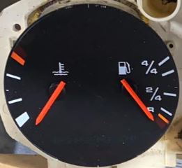
I have an instrument cluster that is supposed to be for a 1979 Porsche 928 US spec and it needs to have the Temp/Fuel gauge part swapped out. What year range Temp/Fuel Gauge would be compatible to swap into the cluster? If anyone has a compatible one to sell let me know. It should have this style face on it:
This is amazingly useful (to those of us trying to work out if their cluster is broken!)
I was just going to post about using an Arduino to test the cluster - my problem is the fuel sender level. Unfortunately, the spreadsheet misses out the fuel gauge from the test plan.
For my 1979 car, I will ground L4 via a resister somewhere between 10 and 80ohms (that is roughly the range I get from my sender unit).
But my question - does anyone know what voltage I should see at L4? at the moment I have 0v but I think it should be 5v (which is why I started this cluster journey)
Thanks
Todd.
Thanks Todd - just saw this, will update the xls
with the fuel gauge test.
Thanks Todd - just saw this, will update the xls
with the fuel gauge test.
great, thanks!
I ended up working it out and making a video about how to test speedo and tacho using an Arduino (mini computer costing $10). It�s on my YouTube channel if you are interested�. But please read the description as there are a couple of bits I missed out

 11-11-2020, 05:54 PM


 George Layton March 2014