When you click on links to various merchants on this site and make a purchase, this can result in this site earning a commission. Affiliate programs and affiliations include, but are not limited to, the eBay Partner Network.
meant to post that earlier...readings at jump post are:
idle no accessories - 14.2v dc
with head and fog lights on - 14.08 v dc
with all lights and ac on - 14.0 v dc
-scott
Your alternator and voltage regulator are slightly higher than mine, +/- 13.5 or so IIRC, but otherwise they seem the same and consistent. Not sure why you would have had that no start problem as it relates to either of them.
I am simple compared to many here, so I would head towards 1. the battery terminal + - connections and 2. the battery itself; I�d have the battery tested at Walmart, they have the best battery diagnostic equipment, in my experience.
Wouldn't focus on gauge activity until I did those two things. Good luck!
The 'dimming out' is much better understood after your video. The fact that the light is on at all on shutdown is interesting, as there's a diode in the excitation circuitry (voltage regulator) to prevent current from flowing back out that terminal.
Basic flow sequence: With the engine off initially, the main diodes prevent current from flowing from the battery back through any of the windings. Turn the key on, and the voltage regulator adds excitation current supplied through a diode, with available current limited by the resistance in the bulb and that resistor in parallel, with the current flow regulated based on the voltage that it sees coming from the windings. Engine is still off, no voltage from the windings, so the regulator is trying to supply max current. That demand is what lights the bulb. Start the engine, and the excitation current causes the alternator to "charge" at the design voltage by regulating the current needed. Besides the excitation current from the bulb and resistor, there's a diode from each of the windings, so that as winding voltage comes up, excitation current to the regulator comes from those windings and not from the bulb/resistor circuit any more. The bulb goes out. When you turn the key off but the engine is still spinning, excitation comes from whatever the alternator is still making. No current should flow back up the circuit to the bulb and resistor, since the diode in that circuit won't allow it. Yours is, and that's what's lighting the bulb in the dash. That excitation protection diode has failed in the "shorted" state. Generally that translates to "needs an alternator" for most folks including me. The problem isn't fatal, just interesting.
As far as the voltage dip when the engine is at idle or slightly below, that's pretty much normal with the factory alternator. We expect the battery to carry that load, and have the borrowed energy restored to the battery when RPMs come back up. As the battery ages and gets more tired, the ability to lend energy at full voltage diminishes, and you notice more dip especially when load is added. The cycling to lower voltage steals more capacity from the battery, dips go deeper, more life stolen, ad mausoleum. Later automatic cars came with a larger crank pulley for the alternator belt. There are some games you can play with smaller drive pulley for the alternator, but it reduces the available contact are for the belt if you go much smaller. The spec tension on the belt is higher than what most would casually apply. Rule of Thumb is that hard thumb press mid span should deflect the belt half of its thickness. Thin ribbed belt doesn't deflect much. Some of the available belts will need some regular tension adjustment early in life to offset early stretching. Miss this, and the belt slips under load and crispifies the ribs. Greg calls this out here, and has shared some good guidance in the past including that the belt is more likely to slip at low speeds when the torque demand is highest. Counter-intuitive really, but good to know.
So for a couple of days the volt light would come on and flicker off as in the video link above. Then it decided to stop altogether again. No light at all, but no charging either. Blipping the throttle to 3500rpm would no longer excite the alternator. I figured based on previous discussion that the alternator (or more specifically the diodes) had finally given up the ghost.
So I ordered a Delco CS130 to do "the swap". Everything went pretty well, and I followed this writeup on RL (even though it was a bit smaller than the CS144): https://rennlist.com/forums/928-foru...1983-928s.html
Well, upon reconnecting the battery, I again got no charge light and only the voltage of the battery on the gauge. It only gave me one start so I put it back on the charger to get it back up to charge - thinking maybe the battery might be too dead to get a charge to start. Then back in the car. No change (although the voltage shown on the gauge is higher). Blipping the throttle would still not get the voltmeter to jump up and start charging.
Checked voltage at battery and at jump post yielded only the voltage in the battery and of course it is dropping (although last week it was 14v+). So - frustrated that the alt must not have been the issue - or it is a combination of other things.
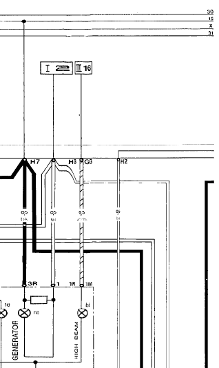
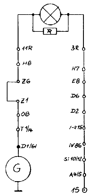
So went back to checking wires again. There is continuity from the alt D+ to pin 1 of the 14 pin connector, and there is continuity from pin 1of the 14 pin to O8 on the CEP (where that line comes in to the CEP). There is continuity between O8 and H8, where the blue wire leaves the CEP bound for the instrument panel. There is continuity from H8 to pin 11R on the cluster, as well as from H7 to pin 3R on the cluster. There is also continuity from either side of the resistor on the cluster all the way to H8 and H7 with it plugged in. It seems as there are no breaks in the wires from the alternator all the way to the resistor on the back of the cluster...the resistor measures 68 ohms, BTW, so it appears to be fine as well.
So - what the heck?
The only other thing I can see on the schematic or think of at all is what happens when H7 goes into the CEP. The schematic (below) shows it goes to Bus 15 - eneergized by the ignition switch. Where is the physical junction of these wires? Perhaps there is something intermittent going on there.
The mystery continues - and the cluster is out (ugh!). Its all good thought because I need to change the odometer gear as well.
So, now it would seem that I am looking for continuity through each of these connection points, or possibly from H7 through the 15 pin on the ignition switch?
If I DO NOT have continuity there, then there must be a break somewhere in the chain, but then I have no idea where these connectoirs are.
I still want to know where the connections listed above are, but I think I made a little more progress today with DrBob's test methodology.
Steps I followed (Remember that I checked continuity all the way from the plug into the alternator 'L' connection all the way through the resistor on the instrument panel):
1. Disconnected 14 pin connector
2. Turned on ignition
3. Grounded bottom "car side" of pin 1 on 14 pin. Dash Charge light lit up. This was unexpected, as I believe this confirms that the wiring on the inside of the car checks out.
Then...
1. With ignition on and 14 pin connector still apart...
2. Tested for voltage at pin 1 on the bottom half (car side) of the 14 pin. Got battery voltage. Also unexpected, as I believe this means that there is a clear path from the ignition switch 15 bus through the instrument panel and CE panel all the way to the 14-pin.
Next, I will test the voltage with the ignition on all the way to the 14 pin...I should see battery voltage at the connector at the alternator for the 'L' pin. Remember this is a Delco CS-130. I suppose I can also test the gharge light on the dash from the alternator connector as well.
Based on symptoms in the video above, I had hypothesized that the "dimming out" of the charge light could have been happening if there was no battery voltage present going towards the alternator from the ignition switch, then as the alternator spun down, the charge light would dim out as the rotation slowed down (assuming the diodes were shorted/shot). BUT - now I have shown that there is in fact voltage moving in that direction that should cease as soon as the ignition is switched off, resulting in no light dimming down.
I think you have a failed diode in the excitation circuit in the alternator, -or- a wiring fault (short) in the front of engine harness between the 14-pin and the alternator. Guessing, based on the voltage coming back and lighting the light on shutdown, that it's the alternator. Disconnect the 61/D+ blue wire at the alternator end, and verify from there that you see the same battery voltage with a meter, and that grounding it still lights the light. If that works, the alternator needs a hard look. Unless there's a short in the harness, the only way the charge light would stay on on shutdown is one of the excitation diodes in the alternator failed.
went ahead and tested at the alternator. I have battery voltage on the excite line at the alternator and grounding the excite line at the alternator plug also caused the charge light to go on.
so...either the new alternator is bad or something is not connected correctly.
I think at this point I may see if I can get the Paris Rh�ne rebuilt locally (new diodes and regulator).
First, ground the exciter wire at the alternator and see if the light comes on. If not, problem between alternator and dash.
If ok, next check voltage at the alternator.
Have you replaced the ground cables?
Both of those tests confirm that wiring is good from the alternator connector thru the instrument panel.
This is a CS130D alternator, and it has 4 connection wires on the pigtail in addition to the B+ lead. Here is my latest thought - thanks for following along...
Right now, it seems like the alt is not grounding the 'L' connection when the engine is not running (alt not spinning). I am assuming electrically this is what is supposed to happen, and thus causes the charge light on the instrument panel to come on.
I noticed that the pigtail also has a connection marked 'I', which is switched ignition. Should I tie it in with the 'L' to the blue wire, since the blue wire in the harness is both the lead for the charge lamp (with the resistor in circuit) as well as a switched ignition source (Bus 15)? I don't know enough about this alternator but I have read something related to that on a GM site.
I plan to check the ground straps tonight, but the battery ground to body is new and tightened down good. The Front Engine harness is also new and everything wiring checks out.
If grounding the exciter wire gives you a good light, check voltage in wire L at the alternator with the wire hooked up.
This should be minimum about 4 volts.
Check continuity from L to ground through the alternator. It will be very high, like over 100,000 ohms, but there should be continuity.
Don’t tie I to L.
So as Billu suggested I went back under the car and tested the alternator body to ground...good. While there, I went ahead and added a piece of wire to terminal "I" with the intent of testing it later on. Hooked cluster back up and while sitting in drivers seat, decided to give it a try. Turned ignition on and I have the charge light like normal. Hmmm...unexpected. Went ahead and started car - charge light went out and volts went up past 14. Have not taken a true measure yet. Tried it a couple of times with same result. When turning motor off I do not get the "fade out" as described above any more. So...two problems solved at least for now: Charge light works and turns off as it should, and I am getting more volts at gauge than I was with the old Paris Rhone...and I get 14 volts at gauge at 700 RPM.
Who knows. Will try again in a few minutes and see where we stand. I did remove the extra wire I had tied in to the 'I' terminal, as it was not attached to anything so I have proven that the alt excites with just the blue wire connected to the 'L' terminal.
You've got some serious expertise weighing in above. All I can add is that the z1 z6 involves the alarm, but you probably know that. And since seth turned you onto the electrical training docs, you also realize there is a very detailed section about the alarms therein, with 83 year being last year of early alarm and 84 year being different. Am wondering about that, also, if there is a wire cross feeding either in front harness, 14 pin, else in console. May be worth pulling the side cover and unwrapping harness distributing power to dash from certain panel. I've found my share of scorched wires in that area, some caused by mice, some by short near ashtray, all involving grounds fused to everything else.
Lutz's boards, that's a new one, guess I haven't been keeping up...
All - Thank you again for providing insight as I have worked through this issue. I think I have finally found and resolved the problem. Wanted to update the thread for those following along in the future.
So after replacing the odometer gear (see that thread for info), I went back to working on the charging issue. You will recall that I had a charge light that would come on some times and sometimes not - indicating of course no charging. Well, upon pod reinstallation, I realized where the intermittence was occurring...at the left pod connection itself. I have the Lutz boards, but I believe the problem is in the factory wiring harness connector, which are still used with the Lutz replacement. The pins in the plugs are unavailable, and I mine had some serious bending and deformation, etc. from plugging and unplugging over the years.
I am working on a replacement option and will post if it works, but finding the pins for ANY edge card connector like this is very difficult - no one uses this style any longer so the parts are obsolete from the original manufacturers. So in this case, I had to remove the two pins for the charge circuit (3 and 11) from the connector, and add a length of wire to them and use a second connector to reattach to the cluster. All of the original factory connectors are preserved, just in case. Everything now works fine.
I am working on a source for a slightly different style of pin to see if it will work in the factory connectors and still make a solid connection, and will post if I results are positive.
I would be willing to bet a number of us have fairly mangled pins in these connectors. If you have intermittent gauge readings or lights that do not work, this may likely be your cause as well.
Just for your consideration, I have been working with TE AmpSeal connectors with another automotive project, and have been considering using a 23 pin pair for my 78's gauge cluster if/when I finally get fed up with the intermittent connections. TE Ampseal
The one "gotcha" about the connectors that I linked above is that the male pins are only available as a PCB mount header.
I just noticed that they offer a wire to wire connector option that is similar to the Ampseal line, marketed as Ampseal 16.
Those are limited on the total pin count per connector, but offer up to 12 pins, so might be an option depending on what year is being rewired. (A quick look at the current flow diagrams showed 12 per connector on my 78, but 17 per on an 85...)
The early connector pins are notorious for being easy to bend, when you didnt want them to do that! Watch out also for the multiple ground connection pins , IIRC on the RH connector. Very important to stop misleading readings as circuits try to find ground, and go out somewhere they shouldnt.
jp 83 Euro S AT 57k

 02-16-2020, 07:29 PM