When you click on links to various merchants on this site and make a purchase, this can result in this site earning a commission. Affiliate programs and affiliations include, but are not limited to, the eBay Partner Network.
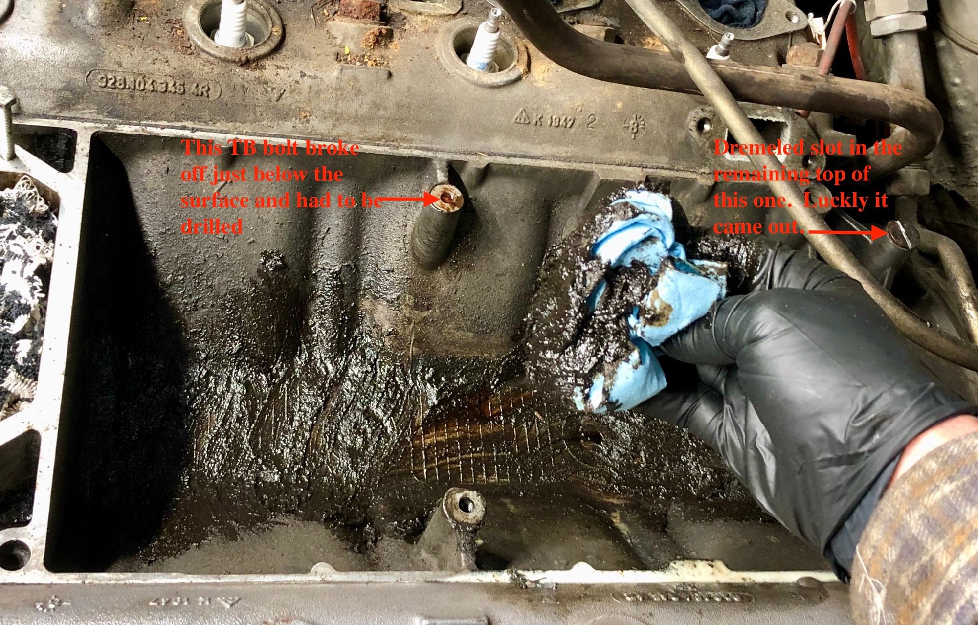
To get good access to get the throttle body off, I removed a number of vacuum hoses and the air pump line down the side. The bonded rubber mounting bolts for the throttle body had petrified and cracked. I could move the throttlebody with my hand. Getting those mounting bolts out were the toughest thing so far. With the middle rubber gone, there's not much to grab onto. Best to dremel a slot in the top and use and impact screwdriver to gently tap it out. One had been corroded and was stuck fast. It had to be drilled out and given a new thread insert.
Once the throttle body was removed...... what a mess. Sort of like cleaning out an old barbecue grill.
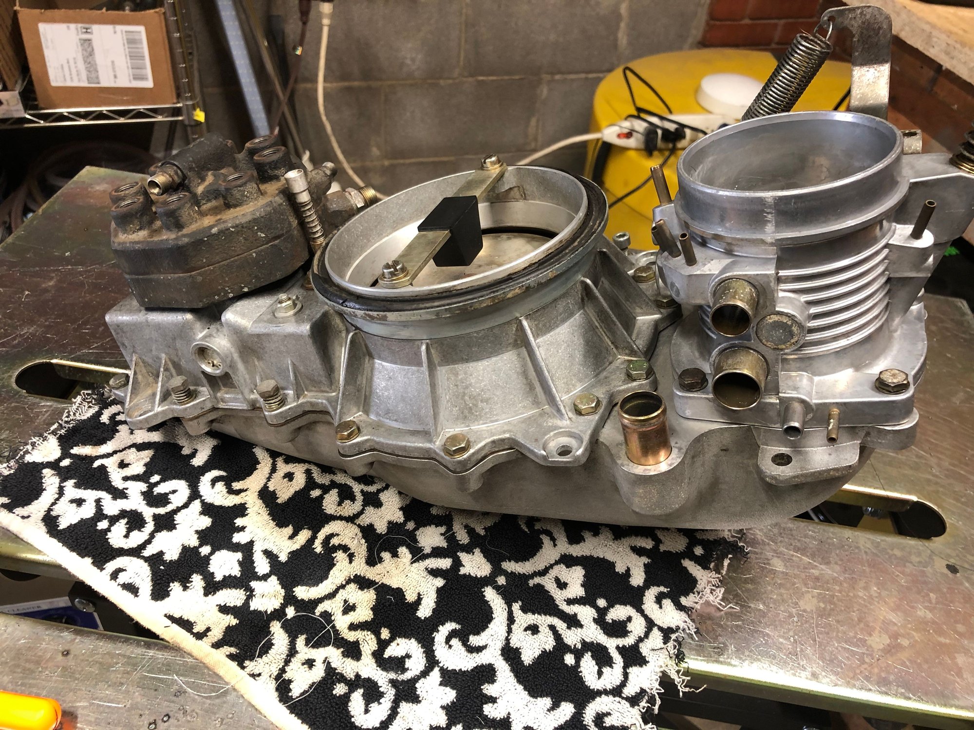
Nice job on that cleanup. I replaced my spider plenum clamp bolts with Allen socket cap versions. Much easier to get a ball head Allen screw in through the spider legs to work the clamp bolt as the bolt head captures the tool instead of trying to keep a flat head screwdriver blade aligned.
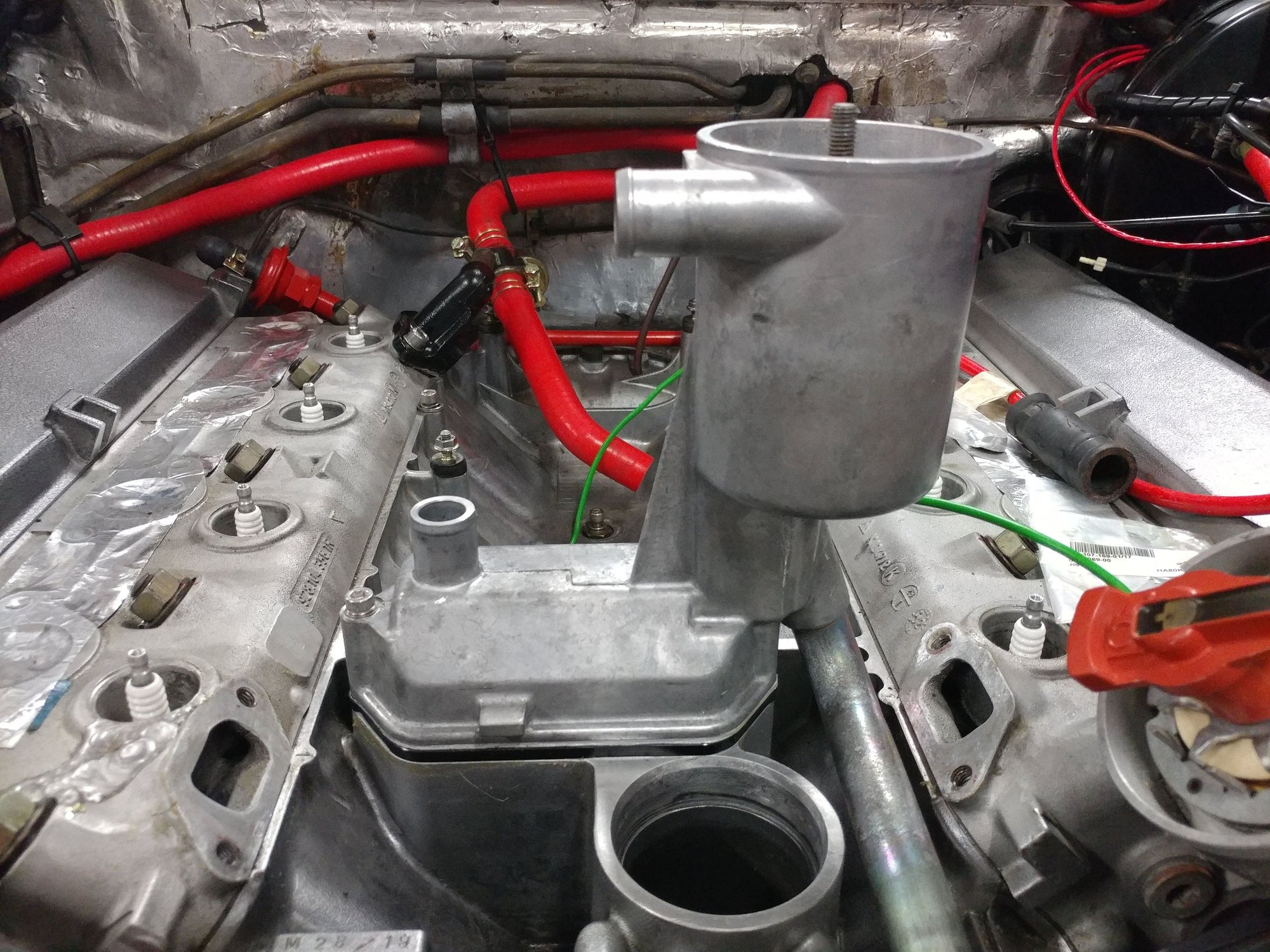
I cut a new connector hose from some silicone I had as well and used rubber fuel pump mounts to hold the k-jet shoe on those mounts. Took some playing around with to get the heights of all components to line up.
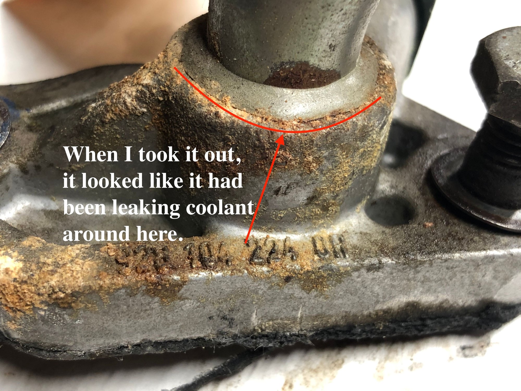
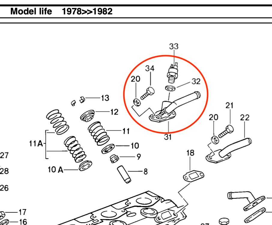
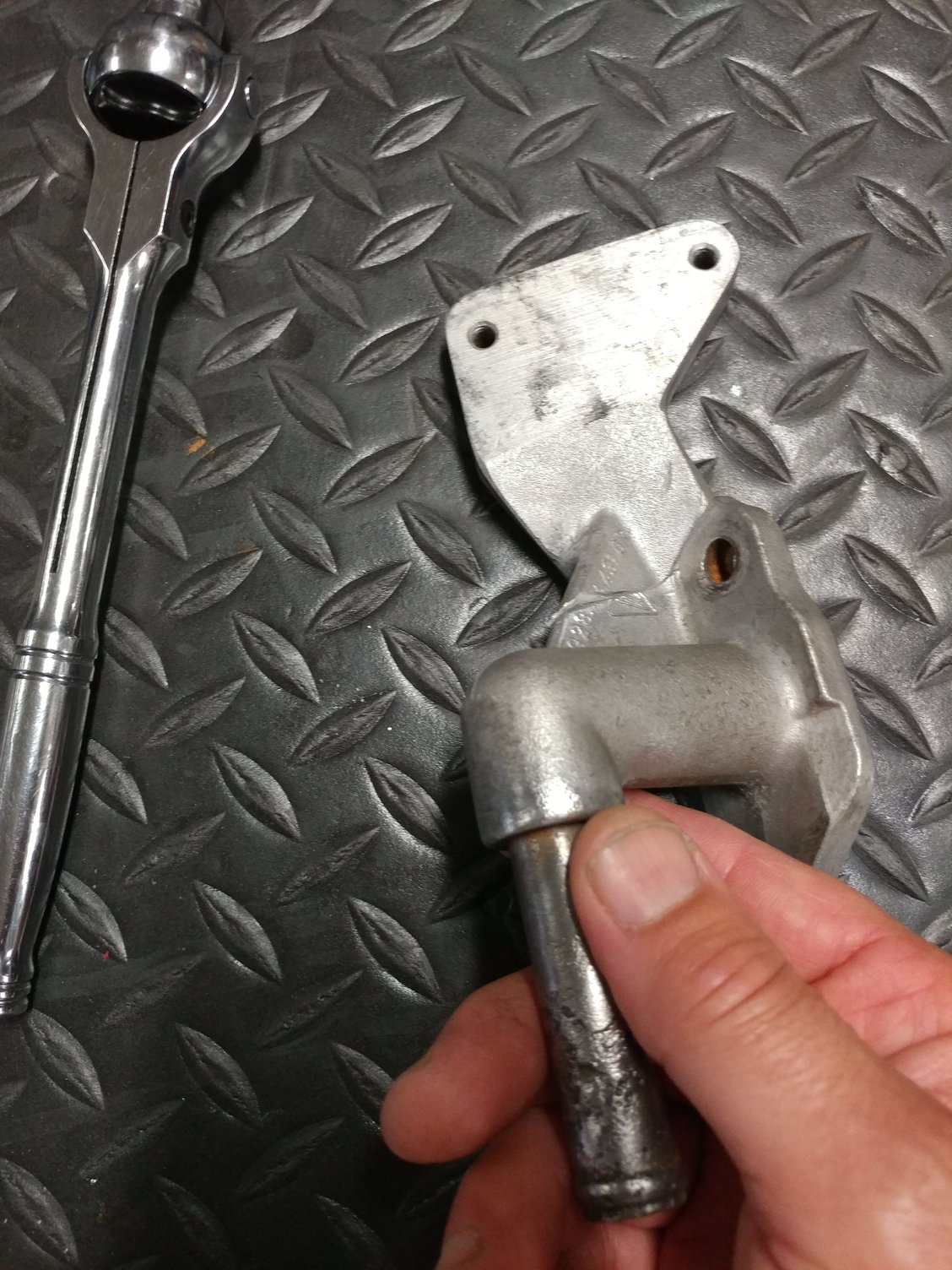
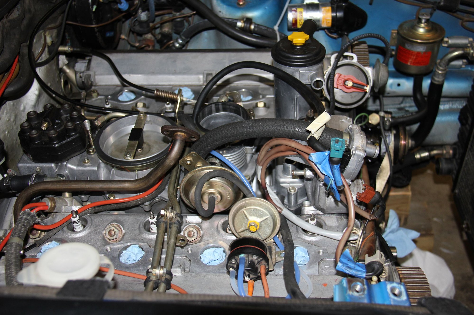
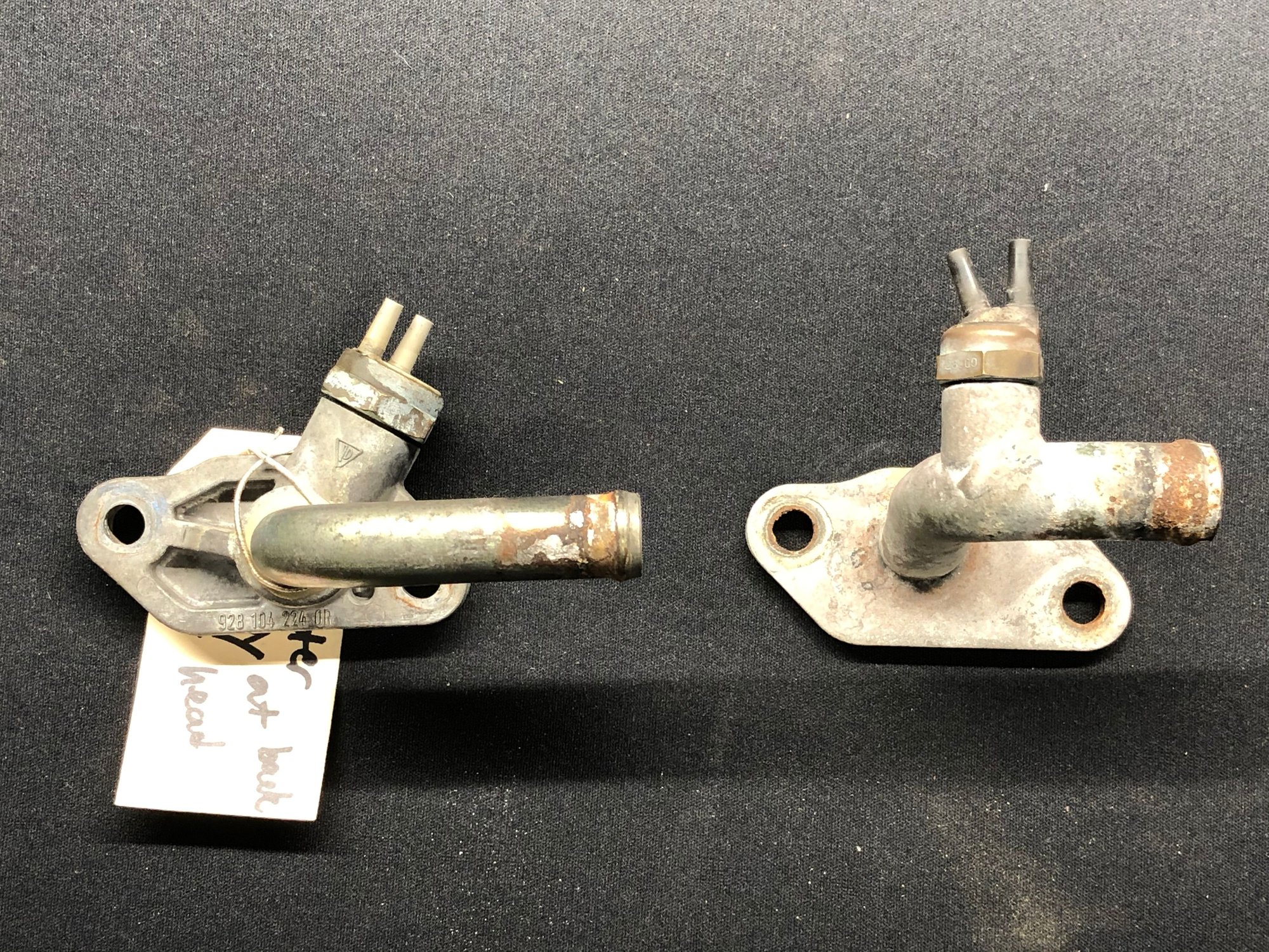
Can anyone shed light on this part circled below? It comes off the back of the head on the passenger side. None of the parts diagrams I can find go to #31 on this particular page. The name for the similar part #22 on the driver side is "adapter" which doesn't give me much to go on. When I took it off, it looked like it had been leaking coolant where the steel tube comes out of the aluminum base of the part.
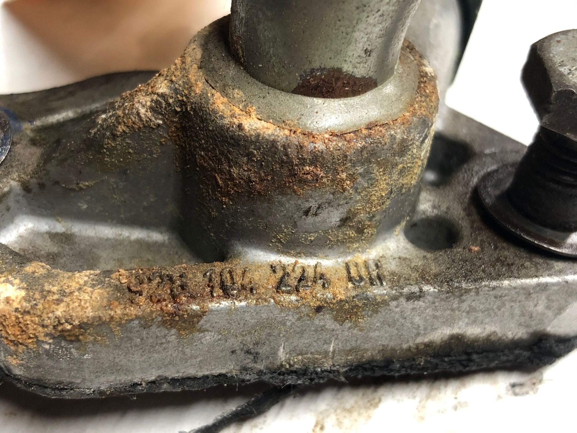
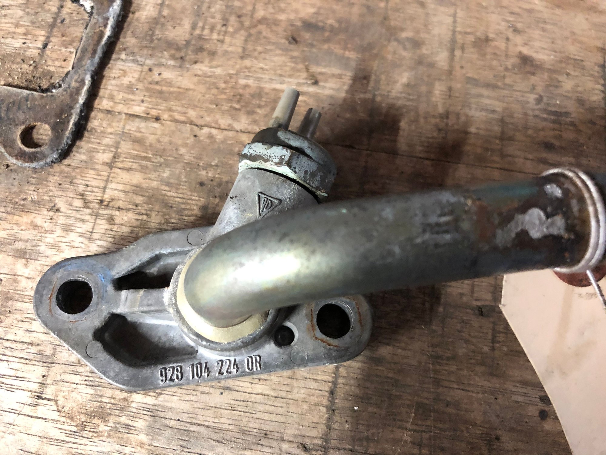
Diagram shows the part, but list of part names doesn't go up to #31 in the documents I've found. The crud makes me think it was leaking at the base of the tube. Cleaned up you can see the part number
Did you have any wires going to the spade terminals on the top?
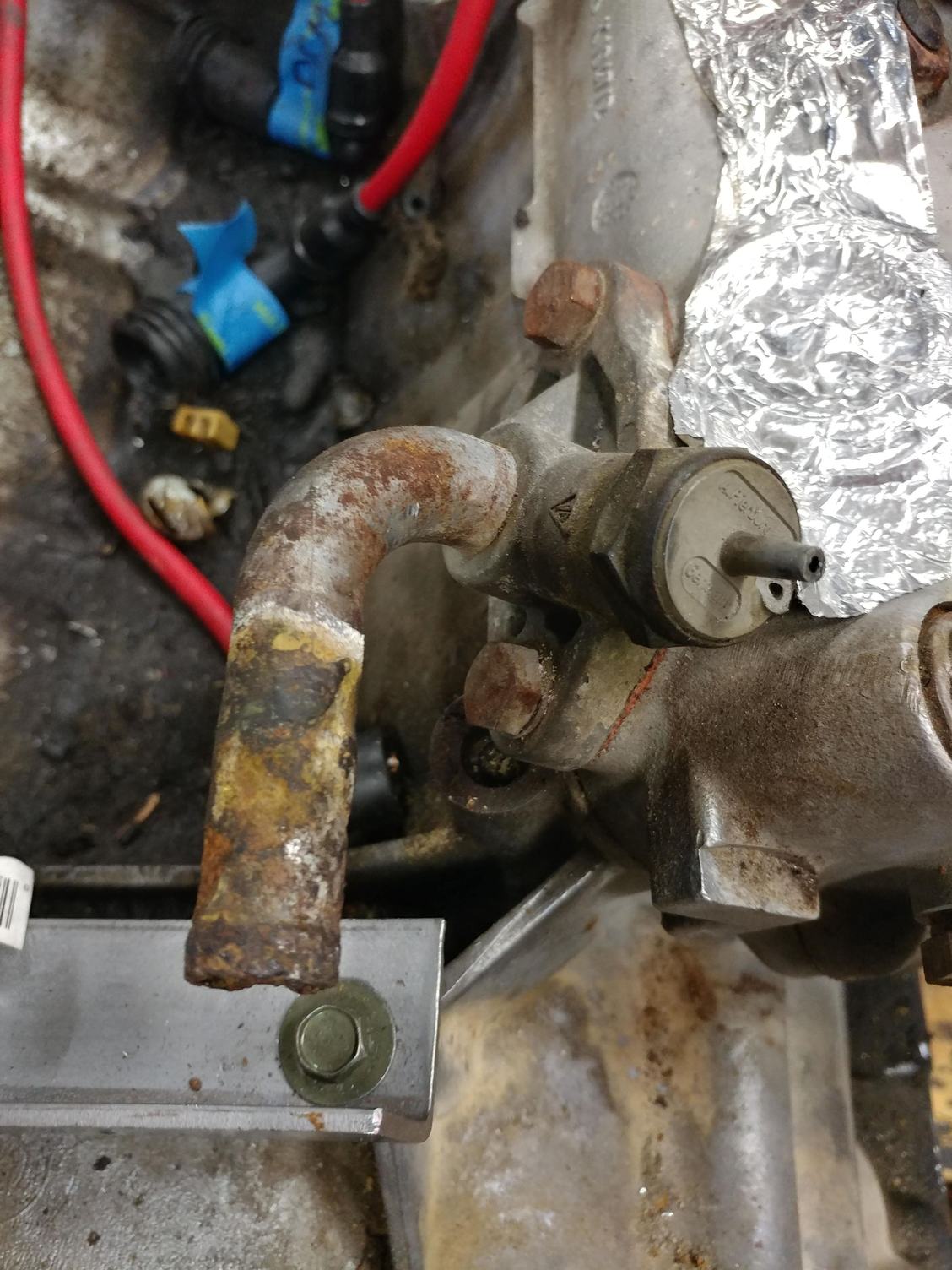
My 79 4.5 L had this part there, with a vacuum port incorporated for some reason. It was corroded and in poor condition....
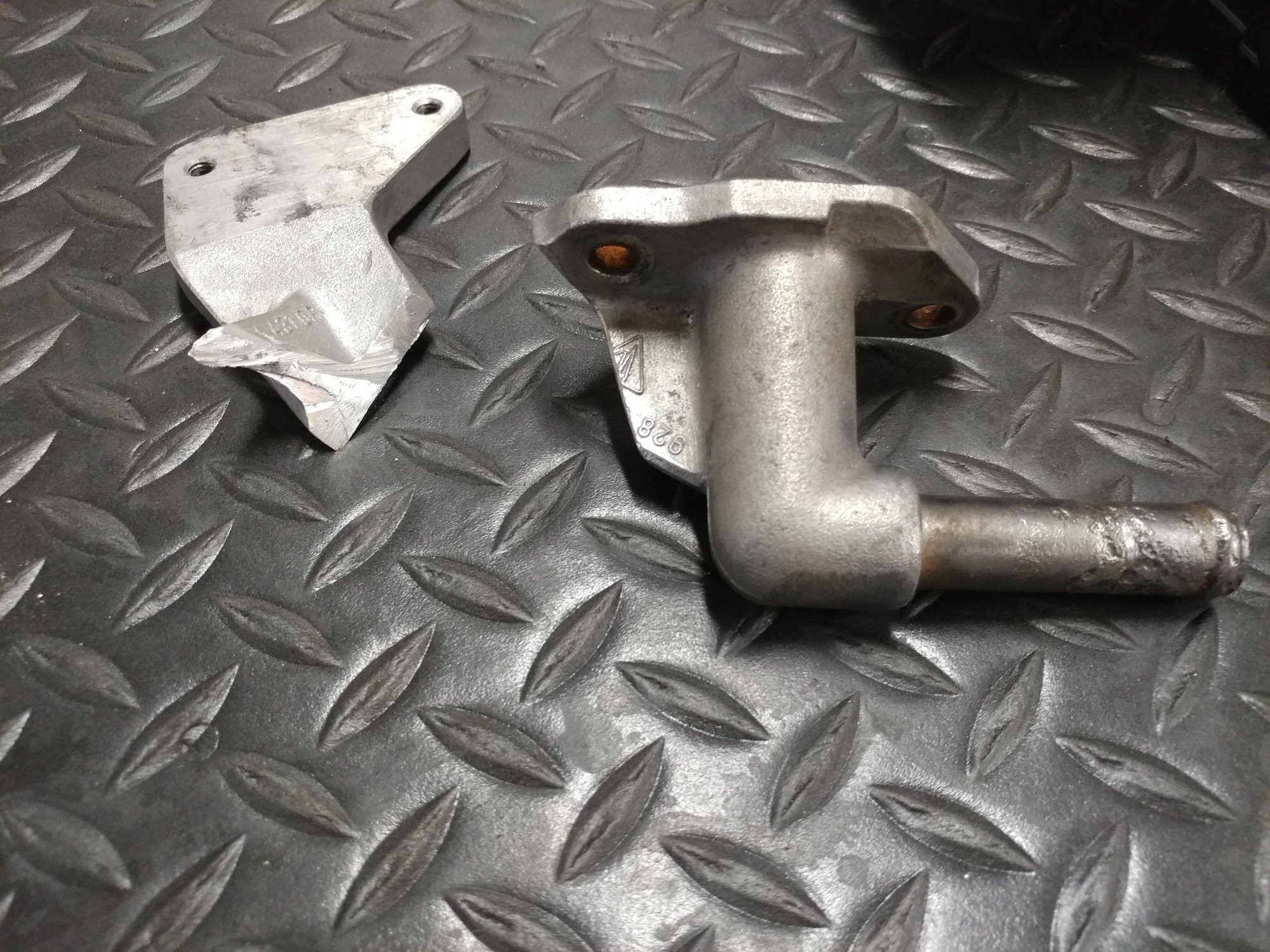
The 4.7 L engine I installed from an '83 in its place came with this fitting that I used because it was in much better shape, but it interfered with the K-Jet setup...
So I trimmed off the offending portion of the bracket...
gave it some paint and used it instead. I plugged the vacuum line that went to the original part and it doesn't appear that I have any issues with this setup. Installed it with a normal water bridge gasket with gasket sealant on both side. Did the same thing with the block off plate on the other side.
Anyone know what the vacuum port on the original fitting was for?
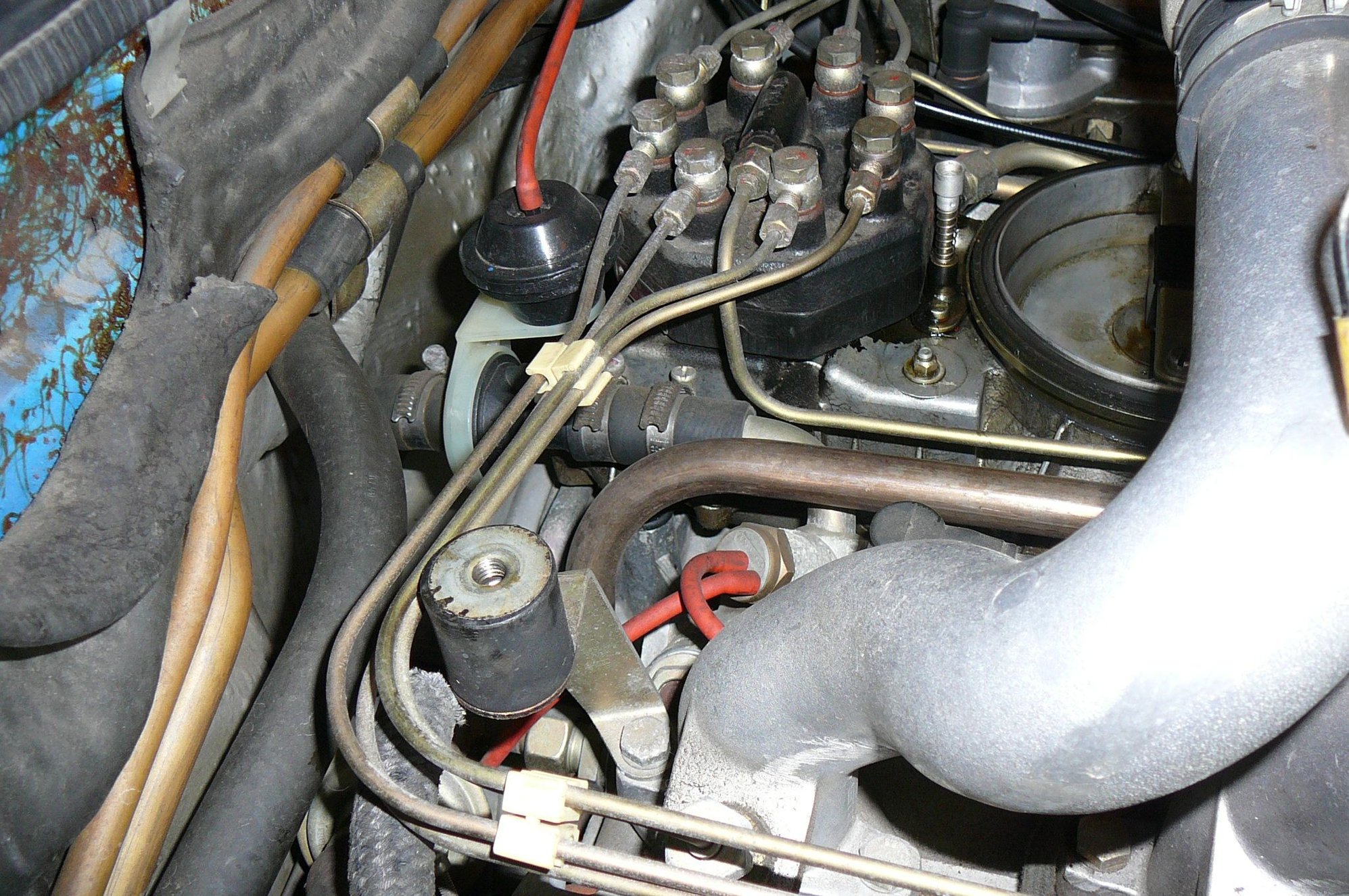
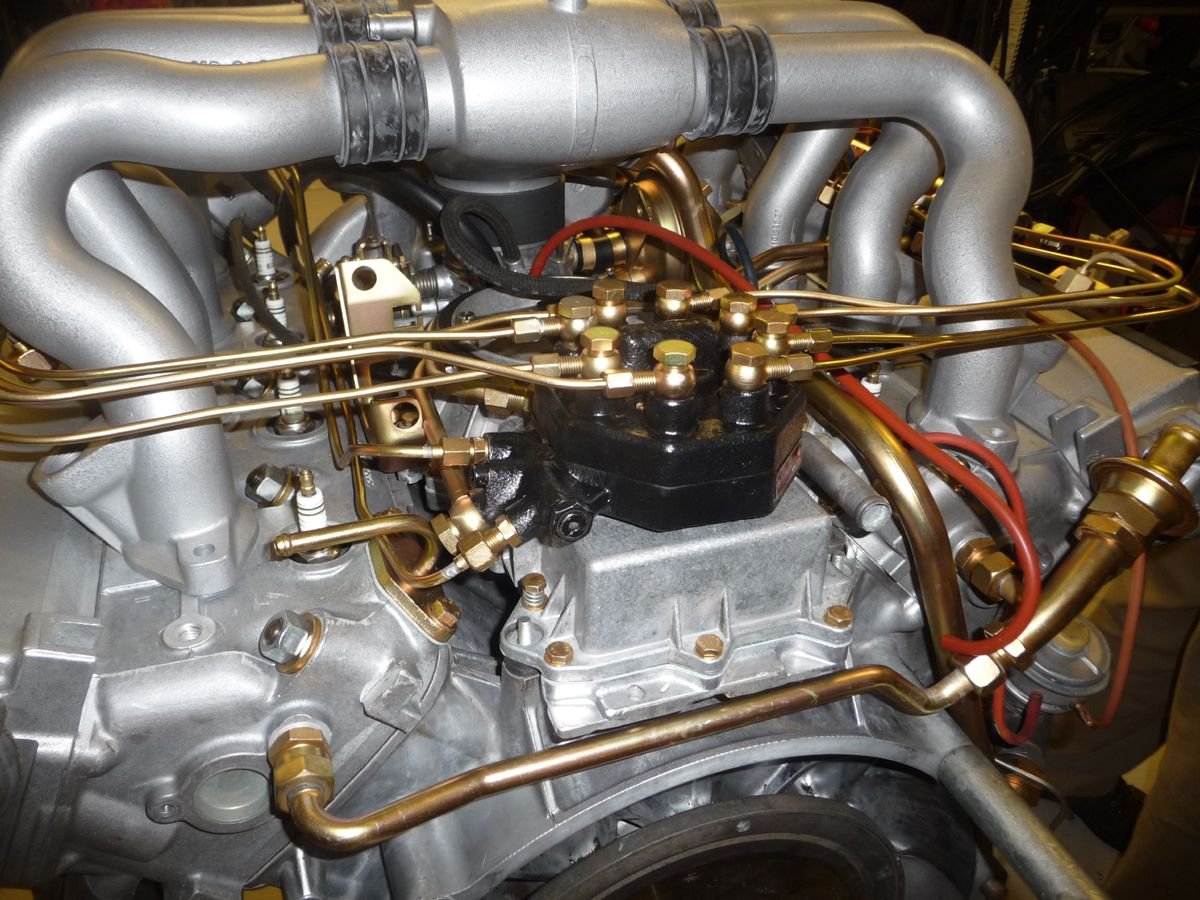
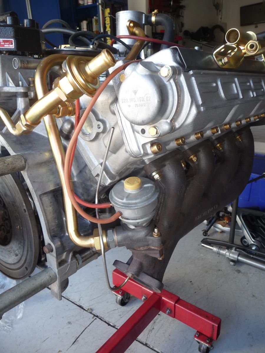
Here are a couple of pictures from when I did the top end refresh on Blumaxx. That part goes to the heater control valve and has 2 vac lines coming off the top.:
Here are a couple of pictures from when I did the top end refresh on Blumaxx. That part goes to the heater control valve and has 2 vac lines coming off the top.:
linderpat, from your photos I now see that one of the vacuum ports on my original piece was cracked off and why I had a single vacuum line connected. Where do those vacuum lines go and what is their purpose on that fitting that has coolant running through it? With them disconnected and plugged, I can't tell any difference in HVAC system or engine behavior. Does vacuum on that valve close down the coolant flow to the heater core if the HVAC is off and if so, what's the problem with letting it circulate with no cutoff?
Pete - one of the lines runs to the central vacuum at the throttle body, and the other line (if I remember) runs down the back into the firewall, where maybe it goes to the HVAC unit in the consol? Maybe Rob or William can chime in as they did a deeper dive with Minerva.I replaced some of these lines but not all of them. I know my a/c still works fine, as does the heat. I'm surprised you haven't experienced any issues with yours. Those are pretty big vacuum leaks.
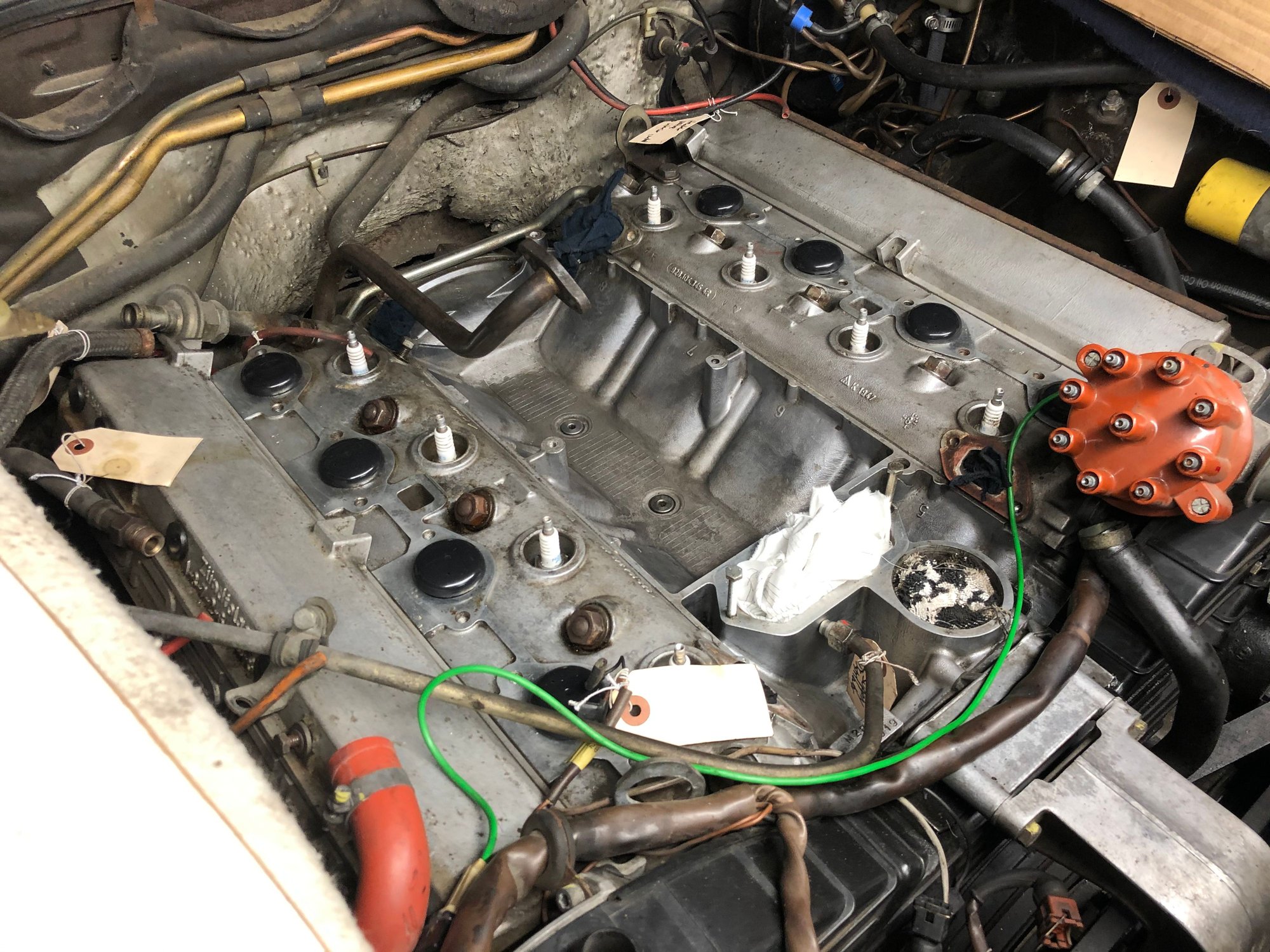
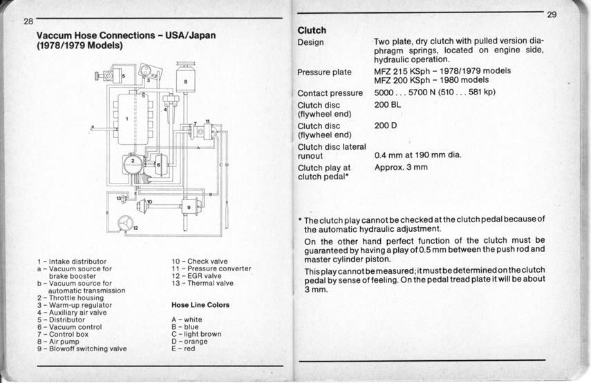
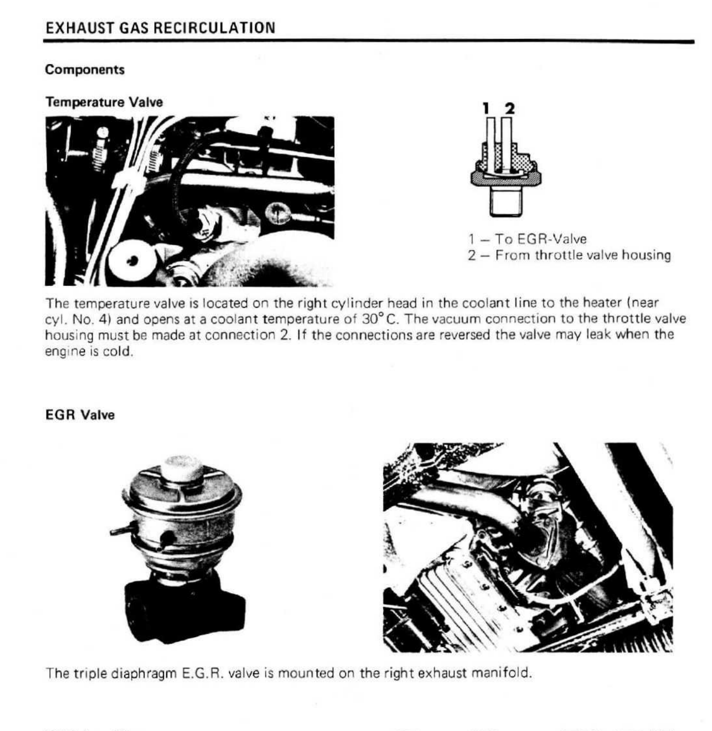
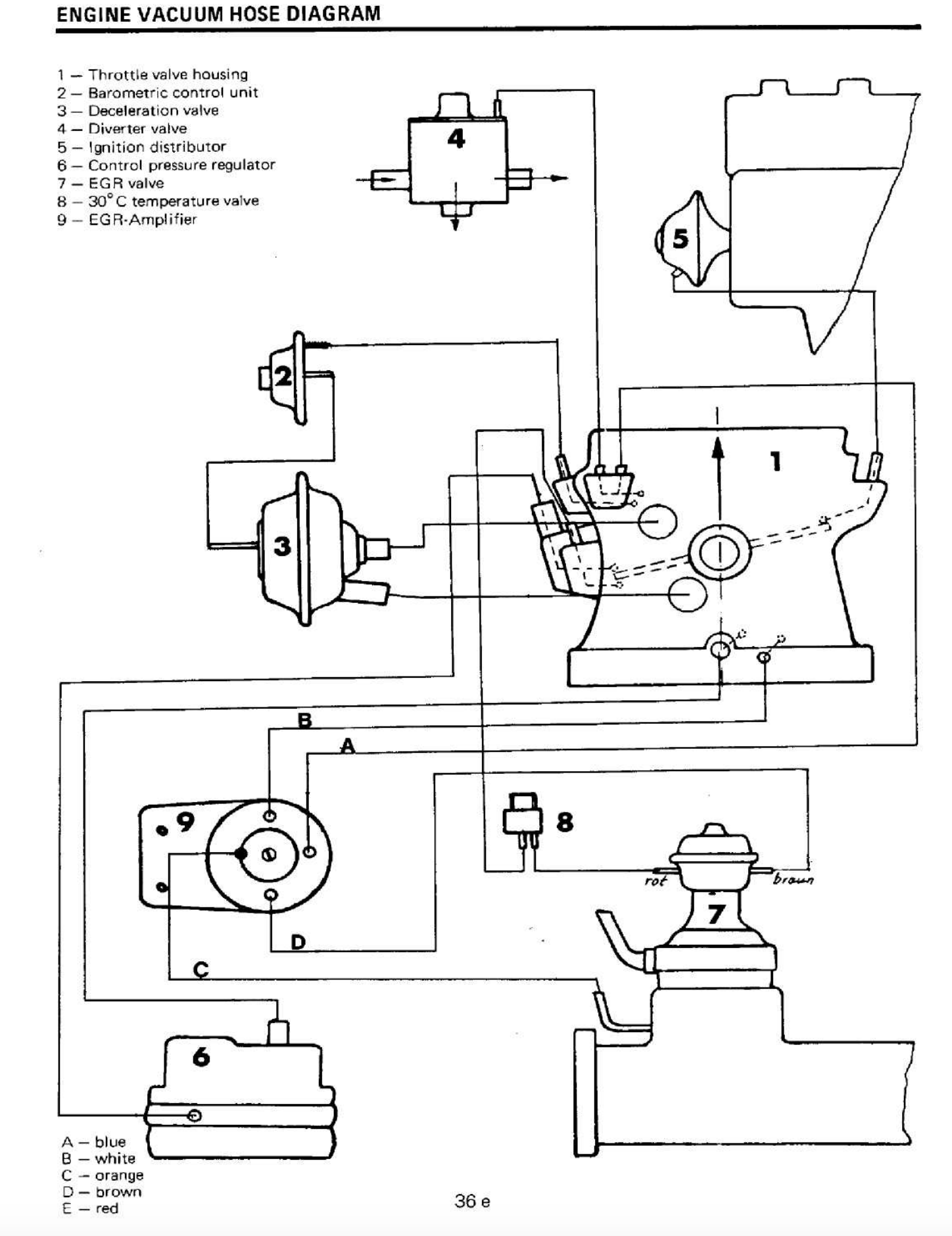
Correction - the bottom vac line does not go into the firewall, but down behind the engine to an EGR valve (US spec cars). The two prong part on top of the water flow part is a thermal valve (item 13 in the diagram below; the EGR valve is item 12). I am not sure of the purpose of these valves on US spec cars, and why they are tied into the coolant flow lines like they are. Anyway, found some prictures from the Minerva thread too. Maybe Rob, William or Jim can help.
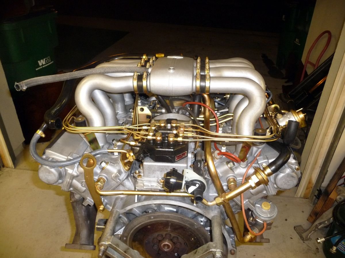
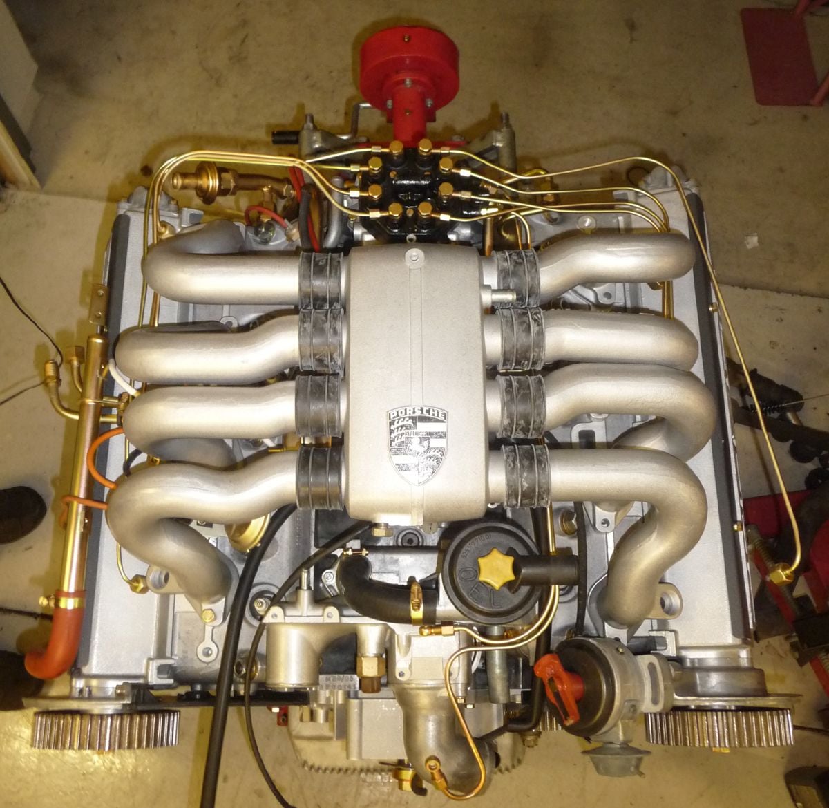
That engine is beautiful. Really makes it easy to see where things go. I don't have that lower rear EGR valve, nor do I have the emissions air pump system. I'm guessing that large metal plated pipe that comes out of the EGR valve and goes up along the side of the fuel distributor must then connect to the air pump system? If so, it explains why I don't have any of that and probably why I don't need the connections to the vacuum port on that coolant fitting.
I will keep a copy of that vacuum line diagram though - that's great. My vacuum line routing is a little different as I'm also using the front spider body port to control vacuum advance and retard under boost and vacuum conditions and for connection to by boost gauge. By using a distributor from a newer car (think it's an '83) that has both vacuum advance an retard, normally vacuum on the advance port advances the timing and vacuum on the retard port retards the timing. With the supercharger, to prevent knock or detonation, you actually want to pull timing or retard it at high boost to protect the motor. By hooking a vacuum line to that manifold pressure port and then hooking that line to the vacuum advance side of the distributor, under boost, the pressure pushes on the advance diaphram instead of pulling on it, which actually retards timing. I have a check valve on the retard port. So under light throttle, I get a little more timing advance but under heavy throttle and full boost, I get a few degrees of timing retard to prevent detonation and have a Knock-link light I monitor to make sure it's not detecting any detonation. I fine tuned my timing advance using the knock light initially,
Wow. That engine really is great to look at. Lots of good info. I kept track of where the vacuum lines go. Mainly I have to make sure it is not leaking where the steel tube comes out of the aluminum base. I figure that fitting is very NLA. Thanks for all the interesting input.
Josh
Found some more info on this thermo temperature valve and what I think can work as an alternative. Like the AAV earlier, this is getting a little arcane, but I like figuring these things out. On removal, my fitting showed evidence of leaking. It is a steel tube inserted into an aluminum base. Those two metals together don't make it easy to reseal once it is leaking. The thermal valve on top of the fitting is supposed to open up at 30C and send vacuum to the EGR valve. Mine didn't seem to hold a vacuum at either port. Running 40C water through it (Just used the tap) didn't seem to change anything nor did cold water. A sharp eyed friend said what about the similar looking thermo valve from a 944. The base is the same shape and the part is all steel so no worries about that leak. Found a $19 used one on ebay so I figured it's worth the test. The thermo valve on it even seems to have a 928 part number but it's different than the thermo valve from my 928. When I run 40C water through it the vacuum port opens right up. When I put cold water through the tube, the vacuum port quickly closes. Works just like my old one is supposed to. The only difference is that the steel tube for the coolant is just slightly larger. I still think I'll be able to get the hose on. Any comments? How the temperature valve is supposed to operate. Vacuum Diagram from 1978 service manual. Thermo valve is part 8. I like how diagram almost looks hand drawn. Original 928 part on left. 944 part on right. A bit crusty looking but thermo valve works and part will clean up. All steel so I'm hoping less chance of leak - if it does, it's something I can braze.
Vacuum Valve for the water spigot is 058 131 851 A new $23.95
__________________
Does it have the "Do It Yourself" manual transmission, or the superior "Fully Equipped by Porsche" Automatic Transmission? George Layton March 2014
928 Owners are ".....a secret sect of quietly assured Porsche pragmatists who in near anonymity appreciate the prodigious, easy going prowess of the 928."
That's good to know. I'm glad I was able to figure out how the valve worked, but I was more worried about what looked like evidence of a leak where the elbow joined the base. Is the spigot itself available?
Thanks,
Josh

 04-02-2020, 10:08 PM


 George Layton March 2014