When you click on links to various merchants on this site and make a purchase, this can result in this site earning a commission. Affiliate programs and affiliations include, but are not limited to, the eBay Partner Network.
#107 has AC and the same 'no electric air valve' configuration as Ed's pic. #1117 does have the valve. Not sure what VIN # it became standard on the US model cars.
Interesting, so early on there was no extra air/idle when A/C kicks on?
-Jason
I found that detailed somewhere (probably one of the threads here on RL), but the earliest cars didn't have the idle-up on AC function.
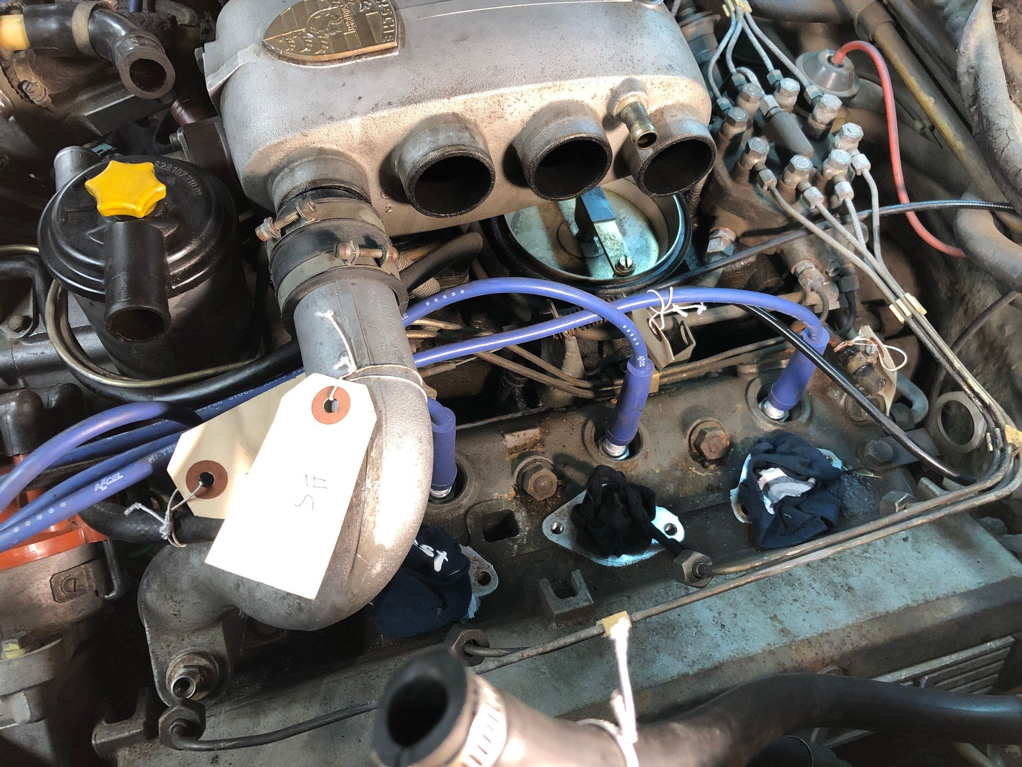
I know my '78 doesn't have the idle up valve, just the main idle air valve that is bolted on top of the coolant bridge / thermostat housing, next to the warm up regulator.
I found that detailed somewhere (probably one of the threads here on RL), but the earliest cars didn't have the idle-up on AC function.
I know my '78 doesn't have the idle up valve, just the main idle air valve that is bolted on top of the coolant bridge / thermostat housing, next to the warm up regulator.
That may explain why when Porsche added the A/C idle valve they just strapped it onto the brace. I've always thought that looked ugly, and like a complete afterthought! Sounds like maybe it was.
-Jason
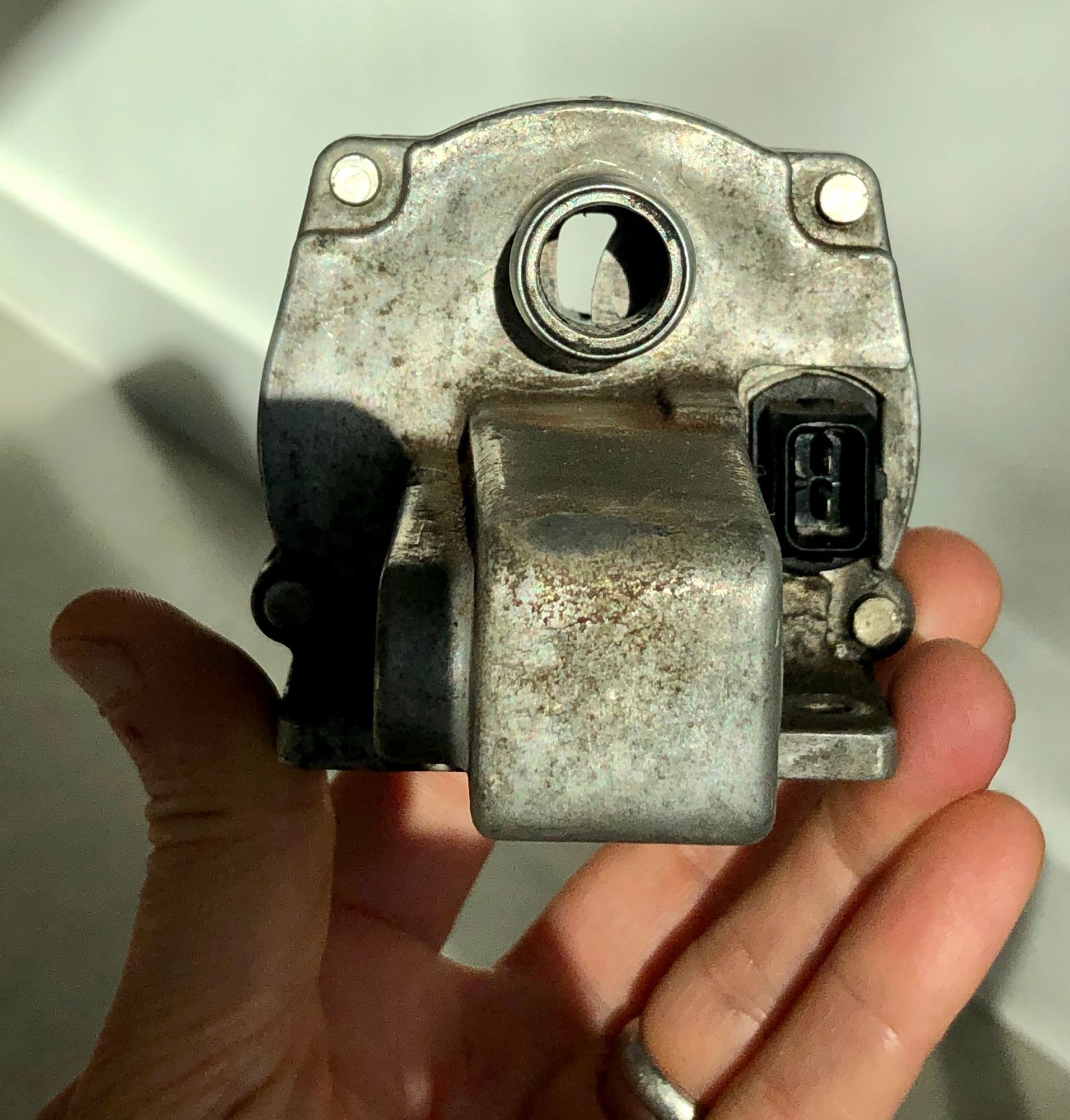
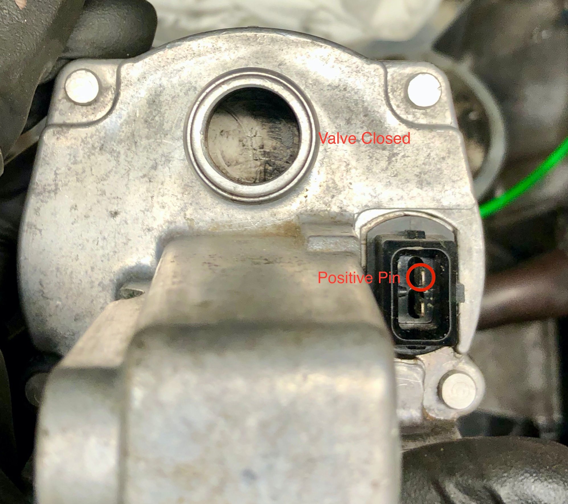
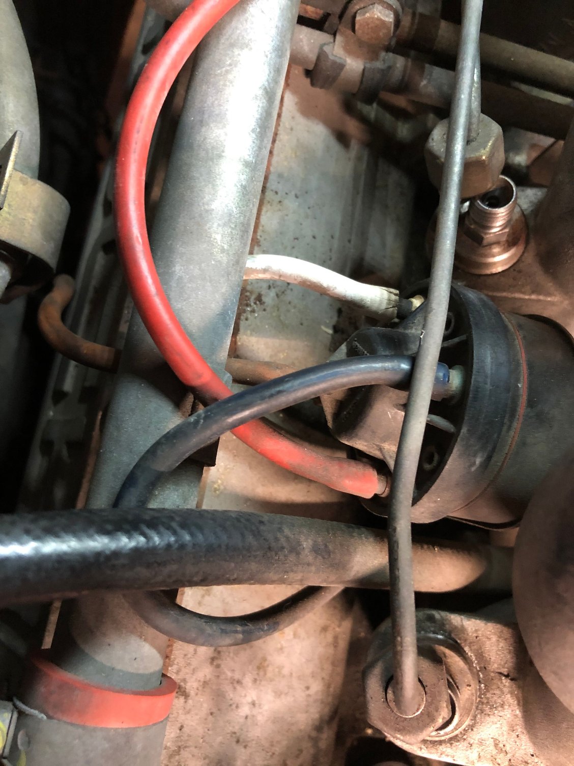
Great info. I'll try to get back on track. The car was starting up quickly just before I started this refresh so I'm not expecting this valve to be bad but I thought I would test it to verify. From other photos I've seen it looks like the opening at cold is correct. I checked for continuity and it looks good. Anybody know which pin on the valve is the positive? I can't see the wire colors on at the connector and I think if I tried to pry back the cover it would just rip.
From what I've seen elsewhere this looks like the correct opening.
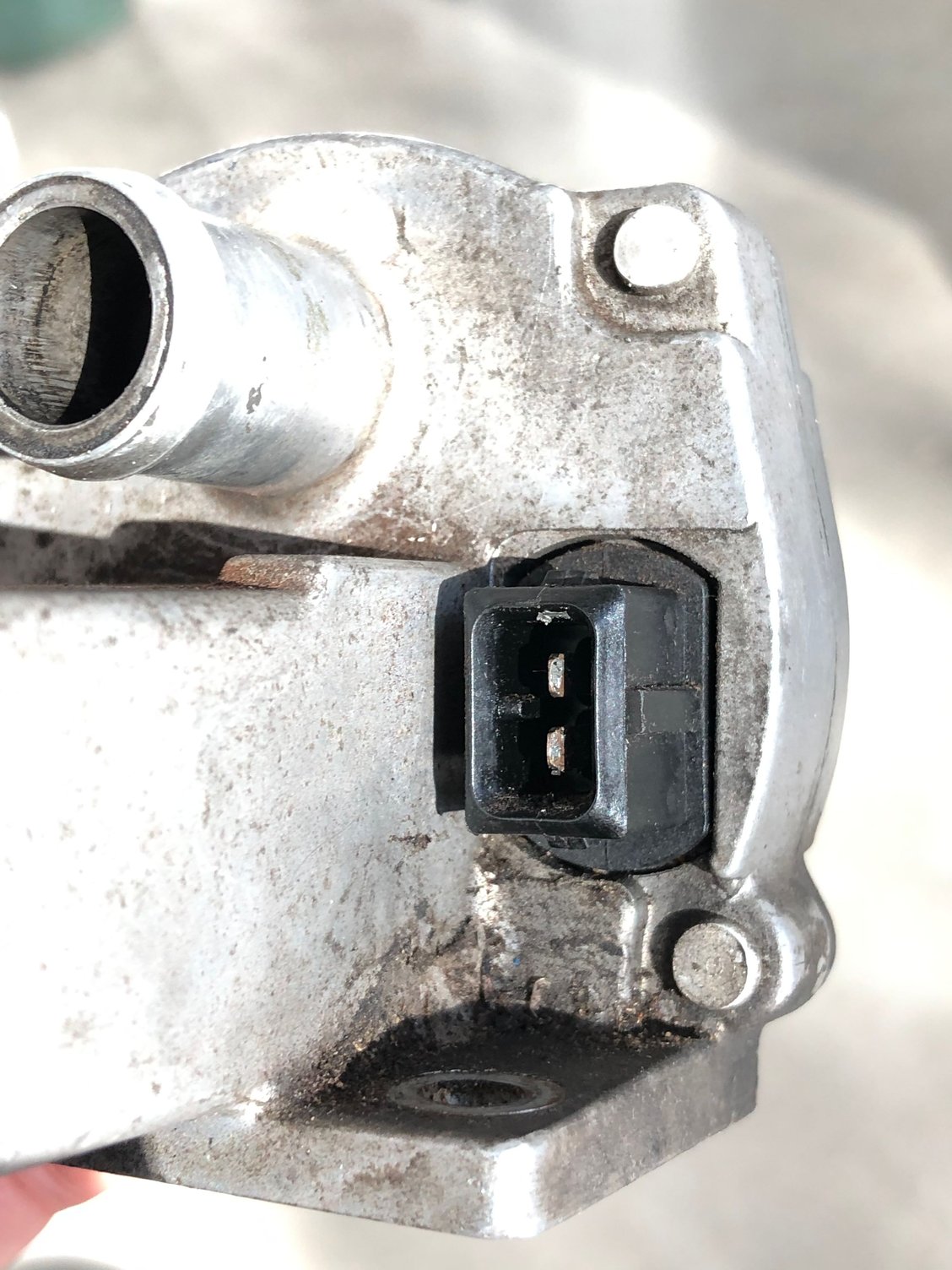
Can't see the wire colors without removing the old boot. Anybody know which pin is positive? Top or bottom?
Can you power up the AC and test at the harness connector to see which pin should be positive?
Looking at the '79 schematic, this would work, or you could check with an Ohm meter and see which is shorted to ground instead of showing a few Ohms resistance.
This connector is parallel to the AC compressor clutch coil, so both will have continuity to ground, but one is through the coil.
I was hoping that schematic would call out pin assignment, but it didn't say which wire should be in which position, though due to it just being a solenoid coil it doesn't really matter for functionality.
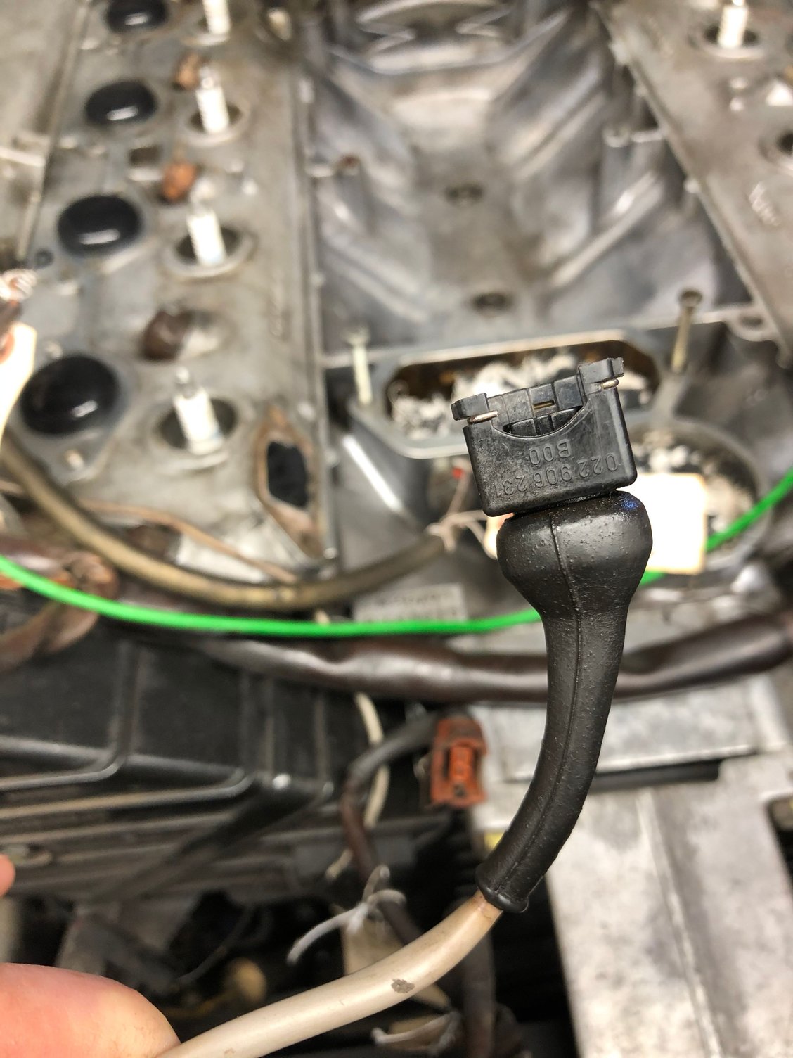
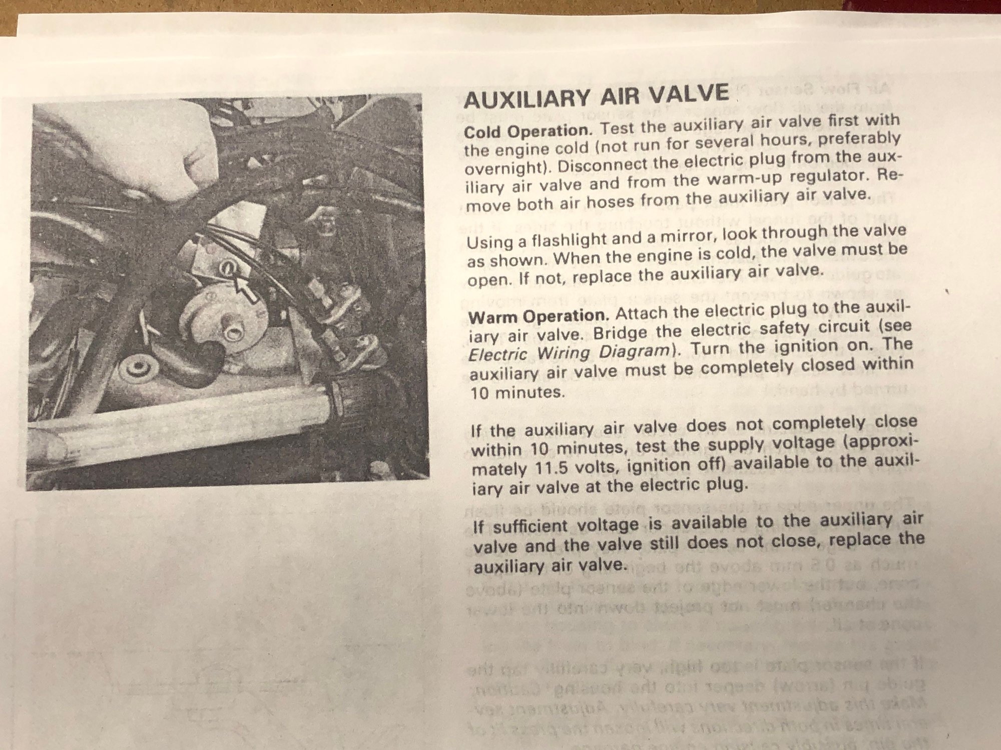
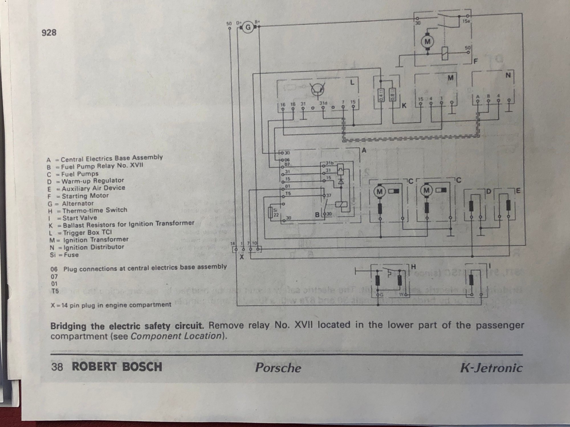
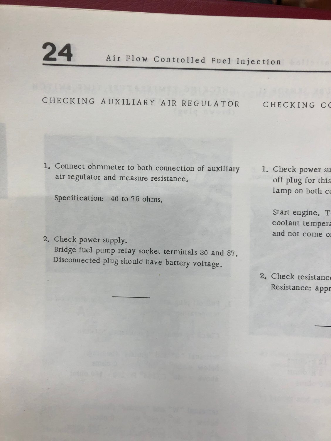
Thanks for the suggestions. Here's what I did to test the Auxiliary Air Valve. In a KJet Porsche manual I found a page on testing the AAV. It says to bridge the electric safety circuit and then says see the Electric Wiring Diagram. On the wiring diagram it says to bridge the electric safety circuit by removing relay XVII (fuel pump relay). It doesn't explicitly say to put a jumper between 30 and 87 but I think that's what is necessary. The Porsche 928 service manual says to jump 30 to 87 to test the Auxiliary Air Regulator (I'm guessing that's the same thing as the AAV? I've also seen it called the Auxiliary Air Device). The problem is that I'm far enough into this that the fuel lines are disconnected so I don't want to energize the fuel pump. Looking closer at the wiring diagram I see that power for the AAV goes through pin 7 on the 14 pin connector. I checked for continuity from pin 7 to the AAV connector plug and found the correct pin for positive. I applied 12 V to that pin and it closed just like it was supposed to. A lot of figuring out with my very rudimentary skills but it was good to successfully test it. I guessed that with a simple heating element either pin would work, but my guesses up to this point have been pretty poor. I wanted to make sure I applied power to the correct pin.
"Bridge the electric safety circuit (see Electric Wiring Diagram). Turn the ignition on." "Bridging the electric safety circuit. Remove relay No. XVII" "Bridge fuel pump relay socket teminals 30 and 87" Applied 12v to the top pin and watched the valve close over about 6 minutes
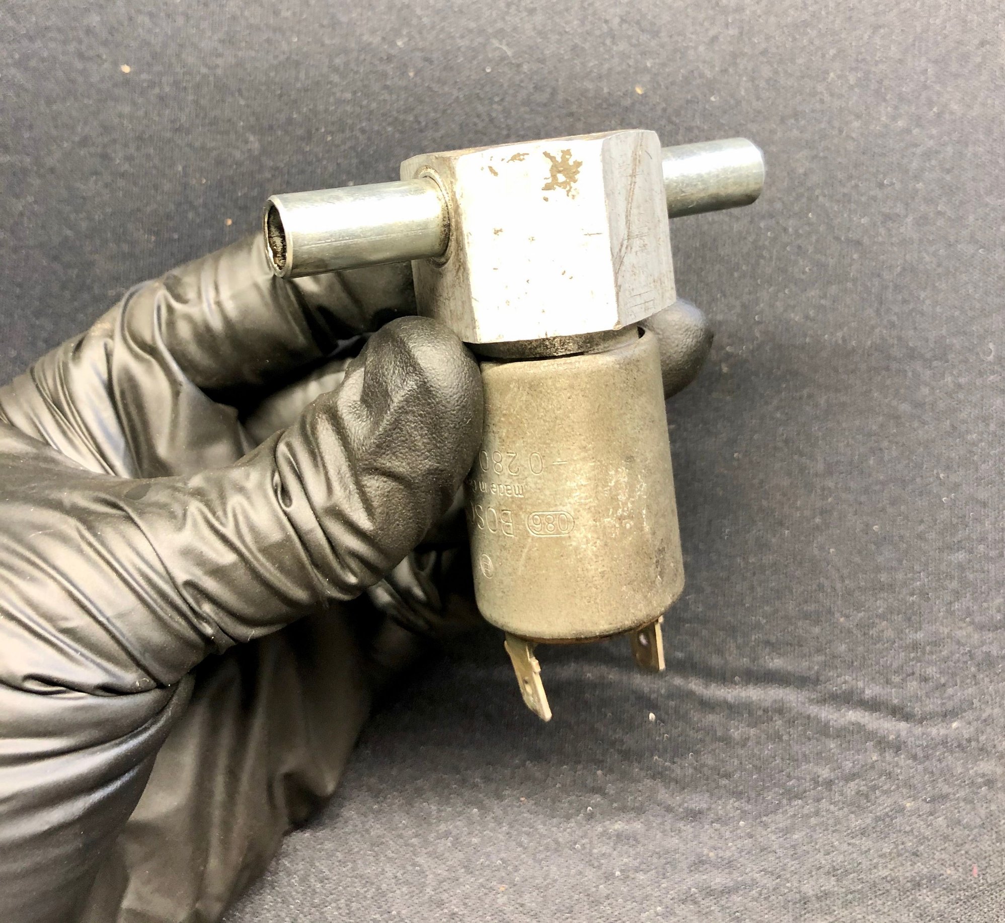
Testing the AC Air Valve that is also connected to this hose circuit was a little simpler but there was a slight difference. On this valve someone had put red sharpie on one of the connectors so I figured that was for power. The difference is that on this valve, it opens immediately when you apply power but you cannot see it open. The valve is on the inside. If you put some air pressure into one side and then apply power you should hear a click and then the valve immediately opens to let air through. When you remove power it seals immediately.
Next I took off the brake booster hose at the intake distributor and started labeling and removing the intake pipes. I also removed the fuel lines at the injectors making sure to counter wrench the injectors. Removed the spark plug wires. On the passenger side, I removed the pressure converter (think I also saw it called the EGR amplifier) and control box right behind it between #1 and #2 intake pipes. Vacuum hoses were brittle and useless. Removing intake pipes crusty old pressure converter
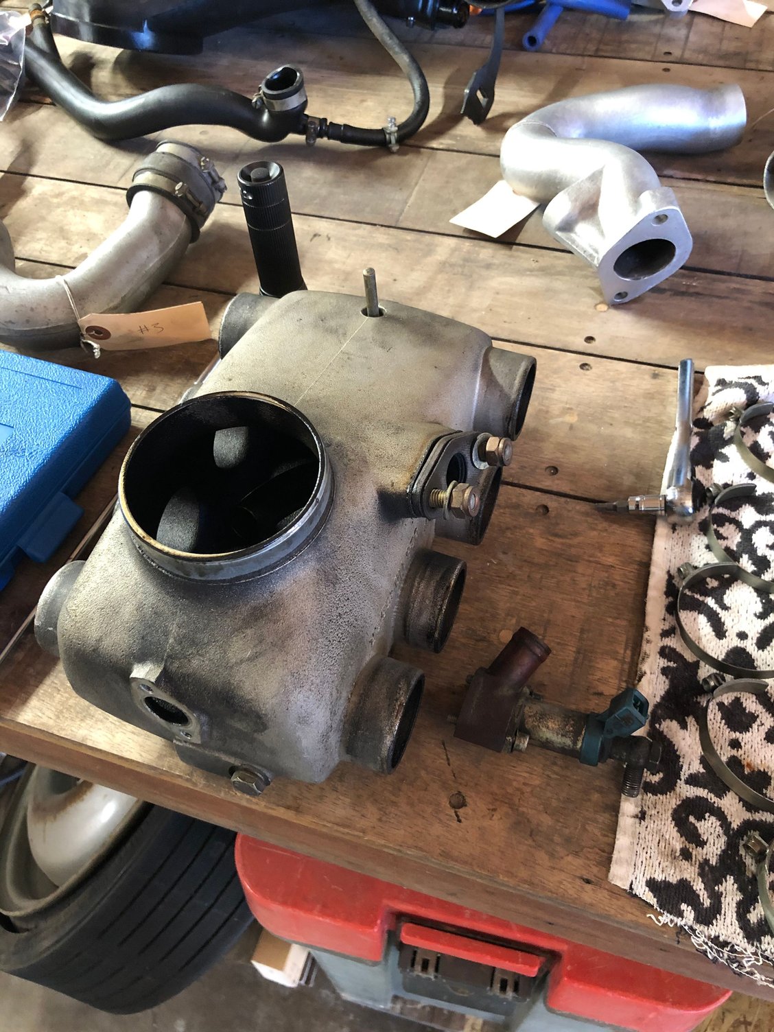
Once that was done I was able to remove the rigid EGR pipe that connects to the intake distributor and then lift off the intake distributor itself. Removed the cold start valve from the intake distributor. Intake distributor and cold start valve released. First attempt at cleaning the pipes behind it.
Late to the party (as usual), but just wanted to throw in my .02...my 78 (serial #30) does not have the AC idle valve. My ‘79 euro has it, and the ‘82 has it. All (3) are stick shift. Don’t know if this has any significance, and is of any help at all...just wanted in on the dogpile!
Once that was done I was able to remove the rigid EGR pipe that connects to the intake distributor and then lift off the intake distributor itself. Removed the cold start valve from the intake distributor. Intake distributor and cold start valve released. First attempt at cleaning the pipes behind it.


 03-03-2020, 12:35 PM