When you click on links to various merchants on this site and make a purchase, this can result in this site earning a commission. Affiliate programs and affiliations include, but are not limited to, the eBay Partner Network.
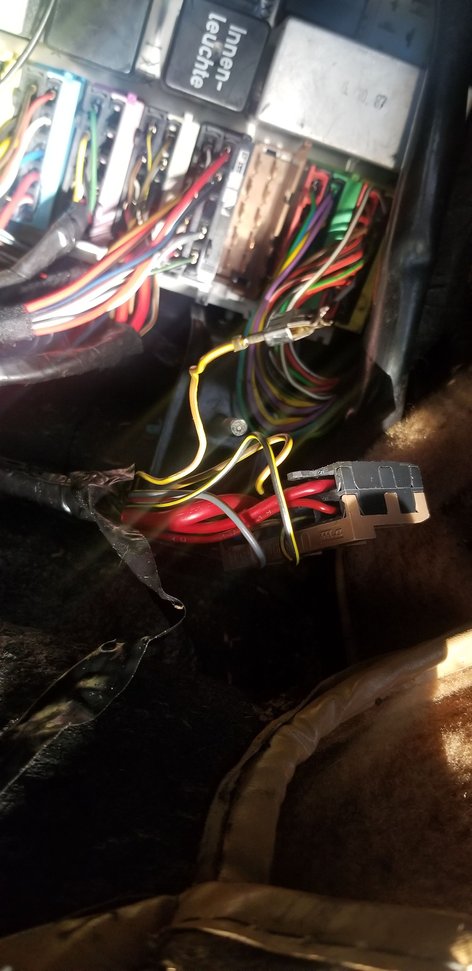
I separated the 6 pin connector in the spare tire well and tested for continuity. And removed the U plug, too.
Solid brown wire (matches up to the solid violet wire on the female connector) on the six pin male connector in the spare tire well has continuity to ground.
I don't think it should. I am wrong. Brown wire supplies ground to the switch ( I think)
The solid violet wire does not have continuity to ground. And that sound right.
Last edited by Kevin in Atlanta; 10-11-2019 at 11:21 AM.
You are correct - my 86 85 dyslexia at play - And there is continuity at U23 to 85.
And there is continuity from the U23 connector side to ground. This leads me back to the wiring to and at the transmission. Right?
To further eliminate the CE panel Disconnect connectors U and V and verify that 85 is no longer grounded.
then I would go to the spare tire well and test for continuity between the Violet and violet/white wires in all gear positions. Should have continuity in P and N only.
then check that the mating side's plug has continuity to ground for the Brown wire, and that the Brown/Yellow does not have continuity to ground with the U plug still disconnected.
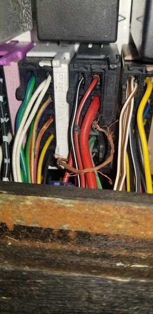
I believe that extra wire is the connection for the manual transmission cars. Since yours is an auto it isn't used and therefore it is taped into the harness. It should have continuity with the other brown/yellow at U23.
I believe that extra wire is the connection for the manual transmission cars. Since yours is an auto it isn't used and therefore it is taped into the harness. It should have continuity with the other brown/yellow at U23.
Well, you're going to enjoy this.
I have no history on this car. The CE panel was replaced from all indications.
No continuity from extra wire to ground. It should go to MPVI - the location with the disconnected ground that I re-attached.
Continuity between the two switched grounds at the harness end - No. There should be.
Continuity from the six pin connector in the tire well to the CE block connector - No.
Continuity from the extra wire at the harness to the six pin connector in the tire well - YES!
Looks like the CE block connector is using the wrong switched ground.
Need to pull the CE panel to see how they wired 85 with constant ground.
Yep...like I said, when you look at the backside of a CE panel that has been tinkered with by a previous owner....you never know what you might find!
(Most recently on an 85, I couldn't figure out why the heater blower had no power. After tracing and testing everything, I pulled the CE and on the backside someone had rewired its power from its original fuse spot to one of the typically-unused fuse spots. ?? Problem solved.)
I'm sure you've seen the backside of a CE panel, but the most obvious alterations will be any wires that are not grey.
-Jason
Neutral switch works. No continuity between violet and violet/white striped wires at the 6 pin connector in the boot unless gear selector is in D or N.
No continuity from 6 pin in the boot to harness end U23.
Continuity from 6 pin in the boot to loose wire on the U harness end.
No continuity between loose wire on the U harness and U23 harness end.
With computers connected XIV 85 has continuity all the time.
With computers disconnected XIV 85 has no continuity.
U23 has continuity with V14.
CE panel looks new. Was replaced at some point.
Could it also have a new U harness?
Alarm has been bypassed. Probably chasing a no start.
Based on this info I would suggest that you get the WSM out and identify the ground wire/s that were removed ,
this should be pretty easy as you can test where the other ground wires go and this will lead you to the ones that are missing.
NOTE as the missing wires will tie into the same ground point as the ones still there, use the WSM to see this.
The missing 4.0 ground is the ground to the manually equipped cars.
Edit: The two smaller gauge ground wire that were not connected to the MPVI ground point are for
I looked at the harness on my other 89S4 and traced the wire into one section of the harness. Using that knowledge to looked at the same harness on the 89 I'm working on.
There is no evidence of that 4.0 brown wire ever being a part of that harness.
The harness at one indicates it was destined for an automatic and the other end at the harness was configured for a manual transmission.
So, moving on...
Don't care about the broken ground from the U23 wire except that I need to swap the loose wire for the ungrounded wire.
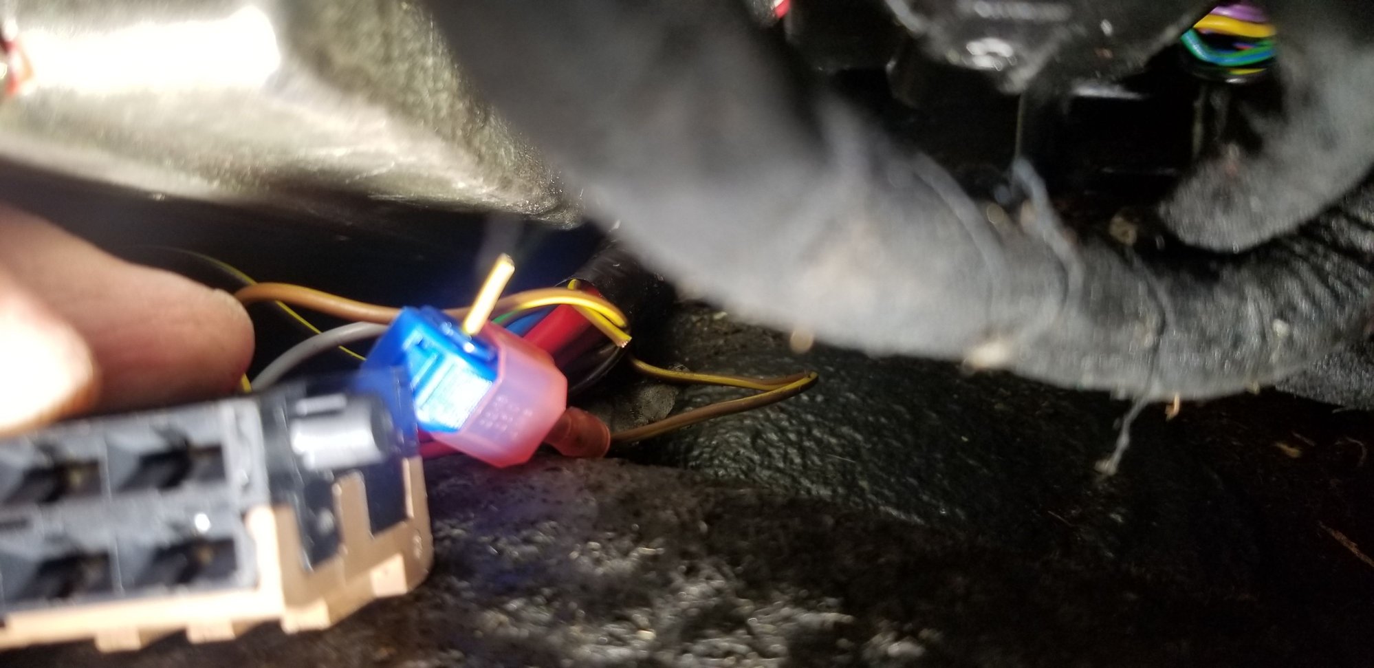
Rather than attempt to extricate the clip from the U connector, I'll use a mechanical solution to connect it to the existing U23 wire (No ground, no foul).
That's the easy part. I still don't understand if constant ground to XIV's 85 is right. 30 on the LH is Automatic Idle Drop.
Last edited by Kevin in Atlanta; 10-13-2019 at 04:30 PM.
Reason: Added more information

 10-11-2019, 10:50 AM