When you click on links to various merchants on this site and make a purchase, this can result in this site earning a commission. Affiliate programs and affiliations include, but are not limited to, the eBay Partner Network.
Freeze Switch question
I am getting between 9.5 and 11 volts at the freeze switch. Is this enough to run the compressor?
See my second post in this thread. It�s not about voltage. It�s about current.
If it is it means that the relay in the head is faulty. I assume I can just replace the relay or do I have to send the entire head unit in to have it rebuilt?
Doc Brown rebuilds the head units with a 5A relay and sends you an inline fuse holder to put a 4A fuse in the clutch circuit.
When I bought this car it came with every record and the owner never thru out any parts that he replaced. I have a the head unit the failed in the box from Porsche. Now I have on to practice on.
vb
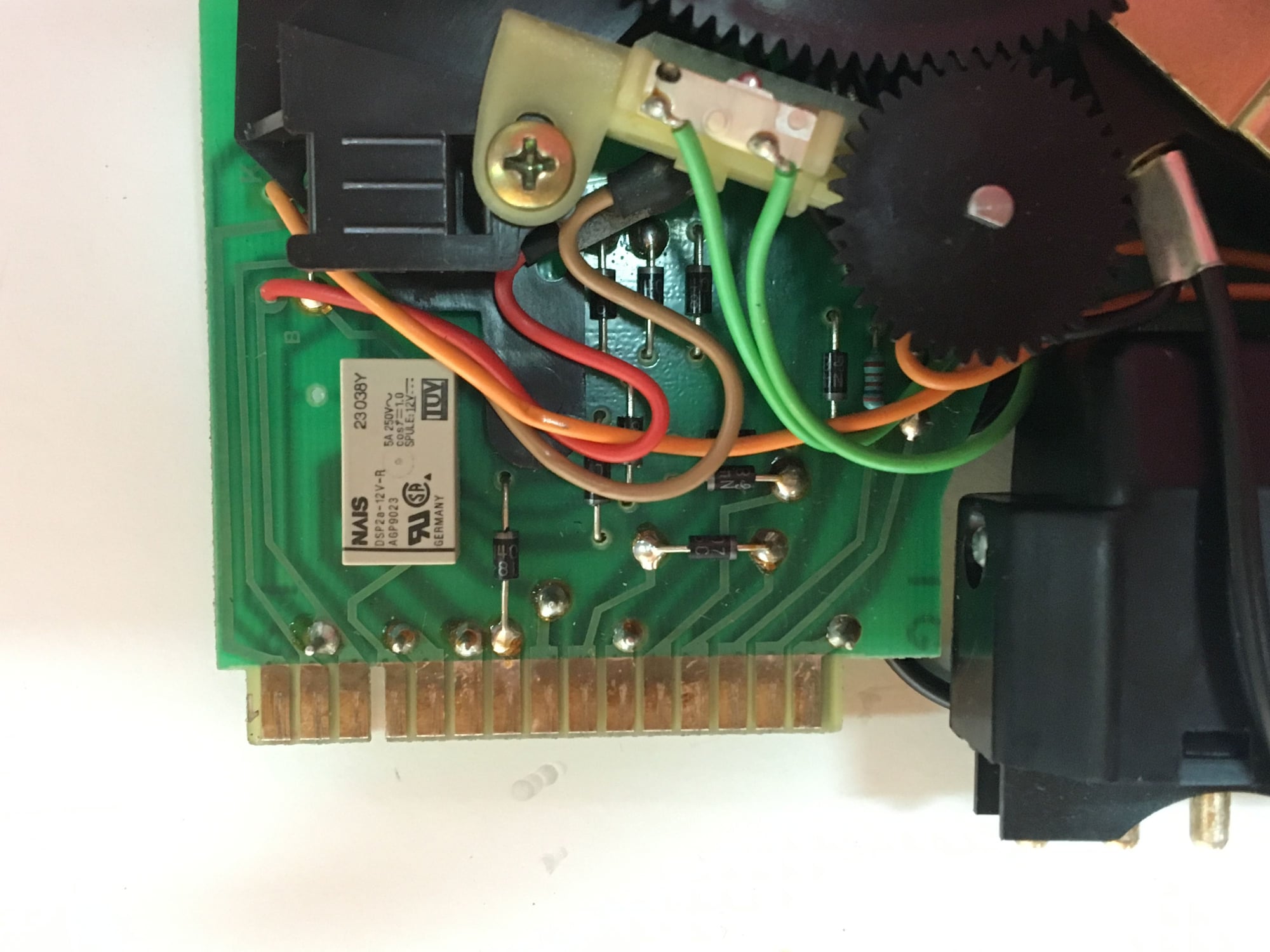
Taking my head unit out and buying a new relay from my local electrical store, ready to follow Dwayne's instructions to my surprise my head unit is not the same
Your target is the relay and the terminal connections to it. There's a breakdown nestled in the wiring diagrams with internal components shown in a dashed box. The terminal numbers are 1 thru 15, starting on the left in your top picture. 1 thru 3, the key slot, then 4 thru 15.
The relay connections can be traced on the board if the old relay doesn't have the terminal and contacts diagram on the shell.
-- the relay coil connects to circuit ground via terminal 4 on the board.
-- The relay coil connects through two diode-isolated paths. The primary is from pin 7 (from the AC pushbutton switch, second is from pin 11.
-- The first pair of normally-open (form A) relay contacts has the wiper/arm connected to pin 8, and the mating contact at pin 9. This contact signals the setting motor that the control head slider is in the off position .and. the AC relay is closed (shouldn't happen and don't know the fail-state response)
-- The second pair of normally-open (form A) relay contacts has the wiper/arm connected to pin 5, and the mating contact at pin 6. This contact connects power from the fresh air blower relay contacts to the various HVAC users including the AC clutch via this contact. Supply comes i on 5, switched power to the clutch coil circuit exits at terminal 6.
I have a blow-up detail in my logbook notes of the circuitry in my 1989 control head, with most connection names/functions and circuit board component values included. It may not be identical to your as far as the interior board details, but the pins an d their functions are consistent among the later auto temp control cars. The notes are all in faded pencil so I'd need to visit the drawing again with a pen before it would help much.
what is the date stamp on your board? it looks like you have a newer head unit. dr bob helped me out in this thread, as well as ed scherer, who had the same style unit
you must have meant 1989. that is the same as mine and is different in its pin mapping than earlier and later
I was told there was a board revision and there was another revision later on. do not follow the original Dwayne or dr bob mapping.
you will note the center pins 2 and 3, along with 6 and 7 have continuity. the earlier boards do not
A typical failure of the relay in the HVAC head is that you will get 12v to the clutch circuit but not be able to sink 3A for closing the A/C clutch. (I call this �HVAC Head Zombie Mode�.)
You can test for this mode by putting a 0.5-3A load in the circuit in series. I use a tail light bulb, in a socket with pigtails, between the low-pressure switch connector and a ground.
If you do have a relay that will pass some current but not enough then you *can* simply buy a nice 20a SPST relay from anywhere, then rewire the compressor power line so that the little relay in the head turns on only the big relay which then can turn on the 3a circuit to the compressor clutch. That 3a clutch load is a misnomer: It's an inductive load so you really need a relay rated higher than 3a to properly switch it long term. That was Porsche's mistake: They put a little 3a (maybe) relay in the head unit and it was too small.
I've described how I did it in other posts, but basically I went to the freeze switch and had the line from that feed a coil to a bigger relay then go to ground (need to wire in a ground). Then I took the +12 from the fan emergency temp switch on the top of the motor, put a 5a fuse on it, and ran that line back to the new relay (which I put next to the freeze switch, why not) at one of the SPST points. Then I plugged the line to the compressor to the other end of the SPST connection on he relay and done.
The 5a fuse protects you if the compressor coil ever shorts (that line is fused 20a for the fan if I recall), it's neat, clean, doesn't require butchering up your climate control and the relay in there should last forever siwtching a 100ma bigger relay. Any voltage drop at 100ma will generate an insignificant amount of resistance as opposed to the 3a+ when you try to close the compressor line.
Of course you should document everything and leave it for the next owner. :-) My next trick is going to be using a SPDT relay so I can have the other pole switch on the front fan at low speed any time the AC compressor is on (and let the fan go high speed when the condenser temp switch trips on) but that's for another time.
I was tinkering with a problem that turned out not to be a problem. In the process I re-drew the clutch current flow diagram for my 1989 car in a much simpler style. This may not be identical to other pre-S4 cars, particularly with CE panel plug connection numbers.
Drawing details: The CE panel plug numbers start with a letter for the plug then the pin number. The terminal numbers for device or module connections are in parenthesis. Other connectors are described with the connector T number plus the pin number in parenthesis. Conductor colors and sizes are in the left column. On the right side are device and function descriptions.
Note two connections particular to the S4+ cars. The condenser fan controller gets its signal to run from the clutch coil contact under the AC button in the console. The LH fuel injection controller gets a signal to raise the idle airflow slightly from a second wire connected at the anti-freeze switch.
I left out a lot of the details like how the fresh-air blower relay is triggered. What's important to know here is that the fresh air blower fuse (17 in my car) must be good .and. the fresh air blower relay must close to support the light in the AC button; If the AC button lights when depressed you can assume that the fuse and relay are functioning correctly and move quickly past. In my S4, the two-wire terminal at the freeze switch is the supply side connection, important as you troubleshoot AC relay problems from there.
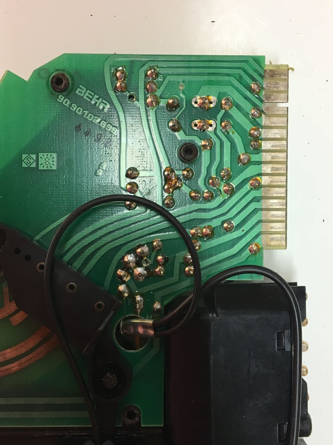
The terminal numbers on the late HVAC control heads are consistent even as there are some internal detail changes.
After reading this I am now wondering if the relay in the board is not defective. So far everything suggested appears to be OK
I replaced #17 (new)
Light on AC switch goes on
Head unit was replaced with a 1990 unit about 40k miles ago
Fresh air blower works well and quiet
Freeze switch is getting enough current in and out
All wires are connected
I wish there was a way of testing the relay in the head unit I start ripping it apart
You "test" the relay contacts when you run the system and the clutch engages. When the relay contacts start to add resistance to current flow, it manifests itself with lower voltage everywhere in the circuit downstream of the resistance. The easiest place to access is at the freeze switch. With load on the circuit and battery voltage in the circuit confirmed by the AC button lighting up, a good relay will show battery voltage at the freeze switch. If voltage is low, the relay isn't able to pass sufficient current to the AC clutch. Remove the load by unplugging the clutch. Does test voltage come back up to battery voltage? It's the relay. It's as simple as that.

 07-12-2019, 10:27 PM