When you click on links to various merchants on this site and make a purchase, this can result in this site earning a commission. Affiliate programs and affiliations include, but are not limited to, the eBay Partner Network.
C'mon, what does that tell you? It worked(balky), they changed the relay, using their own pin connection, it didn't work, the old relay was put back and it worked(balky) again.
This is not rocket surgery. Post 41 has all the info you need. Get a soldering iron, some solder, a few feet of stranded 16 Ga wire, and do the job.
the relay that I found in my head unit has no blue (or yellow) cover on it and looks like it may have previously been replaced. it also has 6 pins.
I thought I read the original had 8? the base surrounding coil is grey in color. does this look correct?
when was the yellow relay introduced? they seem to have different configurations than the blue ones regarding how they function?
my board is dated 1989, and DOES SHARE the same part number as the one on Dwayne's (1988) write up, but looks different in the way
some of the foil is routed.
finally, I took my unit to a local trusted electronics shop to have the new relay installed. when I picked it up, I was told that they changed the pin mapping because the order
I provided "would have damaged the system." OK...�..so I got home and plugged it in, and there was no voltage at the compressor, and traveling backward, none at the pressure
switch, and none at the freeze switch. (fans worked properly) went back to the shop, and they reinstalled the old 6 pin relay. (also tested the new 10A relay, and it works fine.)
back in the car, and everything works as it should, with the old balky relay.
the electronics shop said they wired the new relay exactly like the function of the old relay, and it should be fine. its just a relay, so this should not be a big deal to wire up.
does the pin mapping from the rennlist write ups match the way the original relay works, or is it intentionally wired a different way?
Yes the wiring matches the stock config. Only difference being un-used connectors when using a different relay.
I wouldn�t let anyone touch the head unit that does not have the ability to test it in a car. So best to do it yourself.
You just need a solder vacuum, solder iron, wire and a relay. Practice soldering on some junk electronics if you have not done it before.
C'mon, what does that tell you? It worked(balky), they changed the relay, using their own pin connection, it didn't work, the old relay was put back and it worked(balky) again.
This is not rocket surgery. Post 41 has all the info you need. Get a soldering iron, some solder, a few feet of stranded 16 Ga wire, and do the job.
I am being cautious because I have a guy with 20 years experience telling me I could fry my ecu if I wire the way I asked him to wire. I have a board that looks different from others, and
a 6 pin relay that does not look correct
also, with this old relay, pins 2 and 3, along with 6 and 7 are bridged. I don't think this is correct?
The wiring in the picture is correct. Separate the wiring into three groups:
1. coil of the new relay(little rectangle) to pins 5 and 8 on the PC board. This actuates the wipers to engage the Normally Open contacts, and pick the clutch, and notify the car that AC is engaged.
2. Wiper contacts which has 12V DC present on it at all times. Pins 6 and 7 on the PC board connect to the wiper on the new relay. The wiper is always the icon with the little bent arms that move back and forth(ignore the connection in the default Normally Closed position as those pins are not used).
3. Normally Open pins 1 and 4 on the PC board connect to the Normally Open pins on the relay. These are the pins which do NOT have the wiper touching them. In the picture, pins 3 and 4.
Normally Closed pins on the relay should be insulated as they have 12VDC present at all times. Pins 1 and 2 in the picture, slide a bit of heat shrink over the pins, and heat until they seize on the pins. This will prevent accidental application of 12V from the HVAC head to anything the pins touch.
dr.bob suggested some information that we have discussed thru PM should be added to this thread. thanks for your help, dr. bob.
I have been looking over a number of AC control unit boards online, and I can tell you with certainty, that the pin configuration on my board, along with the copper foil and where they route to the plug connector is different. the board is dated 1989, and the car is a 1990. not certain, but fairly sure, I cannot use the pin mapping that you suggest, docmirror.
has anyone else encountered this issue. the board in Dwayne's write up is dated 1986 (I wrongly wrote 1988) and is different than mine
my tech wired the new relay to correspond to the way the old relay was installed, but he did not cover pins 1 and 2, as you wrote, and wonder if my issue has to do with one of these pins touching something inside the console, causing the problem?
FWIW: my new relay is NTE R14-11D10-12 and their tech support told me it is the 275-218 equivalent with the same wiring.
dr.bob suggested some information that we have discussed thru PM should be added to this thread. thanks for your help, dr. bob.
I have been looking over a number of AC control unit boards online, and I can tell you with certainty, that the pin configuration on my board, along with the copper foil and where they route to the plug connector is different. the board is dated 1989, and the car is a 1990. not certain, but fairly sure, I cannot use the pin mapping that you suggest, docmirror..
Ok, the prints show the same diagram, but the pinout of the relay is not published. If your printout is different from that shown in the picture you linked then, you will need to physically locate the three groups. First group, coil pins. Second group, wiper pins. Third group, normally open pins. Connect those sequentially to the same operating pins on the new relay. As you have not provided the details of your relay, pins, or PC print, that's the best I can do.
Ok, the prints show the same diagram, but the pinout of the relay is not published. If your printout is different from that shown in the picture you linked then, you will need to physically locate the three groups. First group, coil pins. Second group, wiper pins. Third group, normally open pins. Connect those sequentially to the same operating pins on the new relay. As you have not provided the details of your relay, pins, or PC print, that's the best I can do.
as mentioned the NTE relay I used has the same pin config as the RS 275-218:
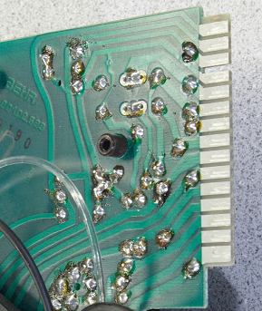
here is a close up of Dwayne's 1986 dated board:
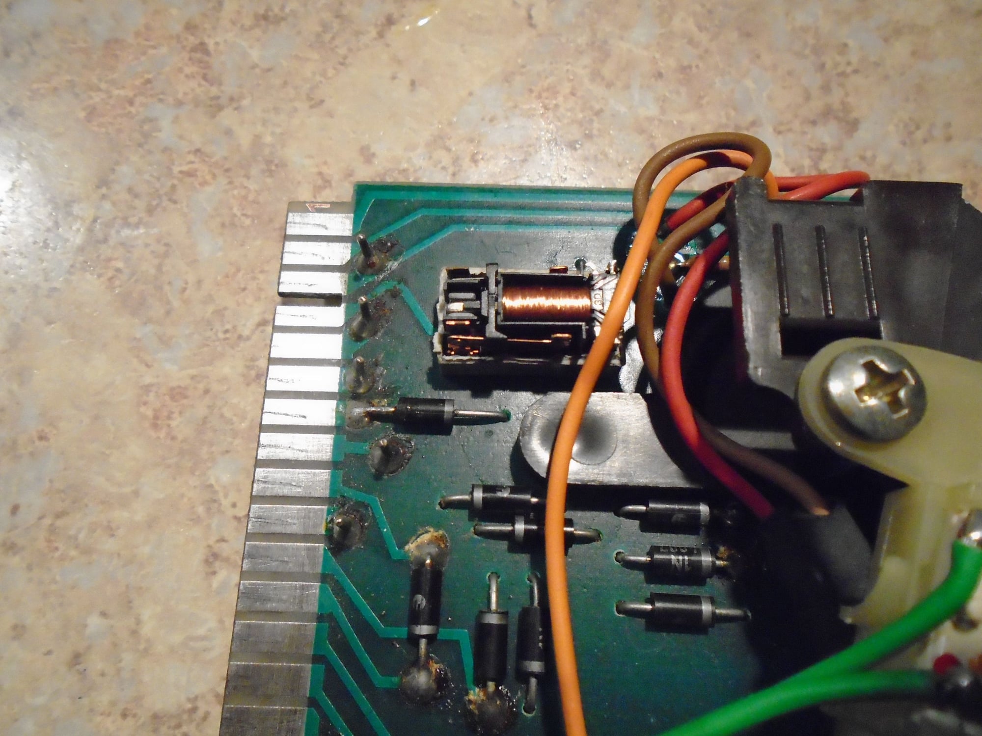
here is pic of my board: (solder a little messy, because we quickly reinstalled the old relay to test; I will clean it up!)
there are many differences in the foil. in Dwayne's you will note foil to the left of pin 5 connecting to the next vertical foil; mine does not have that.
pin number 4 foil runs to connector number 5 (on Dwayne) connector #5 has foil to pins 2 and 3 on my board. those are a few differences.
docmirror, I am thinking that my tech wired the new relay properly, but since he did not cover those hot pins, #1 and 2, one of those touching something
may have cause no voltage out to clutch? other oddity, is that if I left the AC button depressed, and slid the vent slider to the left (off), the lighting on the
AC button remained on, but dimmer than normal. key off, and back on, and the light would go out. do you think those bare pins could have been my problem?
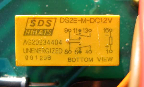
this is a better photo of the top of the relay with cover and diagram from ed scherer who also has a 1990. the underside his board also looks exactly like mine:
all the threads I searched refer to the blue gruner, and the later yellow relay. anyone familiar with this relay?
if my relay is original, and the same as this one, then the diagram on the cover should help figure out the correct pin mapping?
Last edited by merchauser; 01-30-2019 at 06:34 PM.
It appears the pinout for the relay on this board is different than in post 41. I'll see if I can get you sorted out.
Note the location of the coil pins, they are furthest away from the PC edge connector. Those two pins will go to pins 7 and 8 of your relay.
The next two pins are the blanks on the PC, this relay does not use or have pins in those locations.
The next two pins closer to the board edge are the wiper. They will connect to pins 5 and 6 of your relay.
The closest two pins to the edge of the board are the normally open. They will connect to 3 and 4 of your relay.
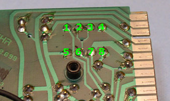
Flip the board over, and unsolder those pins and remove the relay. Looking at the bottom of the PC board, align the edge connector on your left:
Legend: NO(x) to pins 3,4. wpr(y) to pins 5,6. bnk blank. coil(z) to pins 7,8 on your relay.
edge NO.. wpr.. bnk.. coil
I--
I--..... x.... y........... z
I--
I-- .....x.... y........... z
I--
It appears the pinout for the relay on this board is different than in post 41. I'll see if I can get you sorted out.
Note the location of the coil pins, they are furthest away from the PC edge connector. Those two pins will go to pins 7 and 8 of your relay.
The next two pins are the blanks on the PC, this relay does not use or have pins in those locations.
The next two pins closer to the board edge are the wiper. They will connect to pins 5 and 6 of your relay.
The closest two pins to the edge of the board are the normally open. They will connect to 3 and 4 of your relay.
Flip the board over, and unsolder those pins and remove the relay. Looking at the bottom of the PC board, align the edge connector on your left:
Legend: NO(x) to pins 3,4. wpr(y) to pins 5,6. bnk blank. coil(z) to pins 7,8 on your relay.
edge NO.. wpr.. bnk.. coil
I--
I--..... x.... y........... z
I--
I-- .....x.... y........... z
I--
docmirror, thanks for the info provided above; using your legend, I was able to wire the relay correctly, and everything works perfectly!
my tech told me if he wired it up as per the Dwayne/drbob write up it would have damaged the ECU or worse....was he being dramatic, or is that true?
here is how I successfully wired my relay using the pin number legend below:
board pin 1 to relay 8
board pin 2 is not used
board pin 3 to relay 6
board pin 4 to relay 4
board pin 5 to relay 7
board pin 6 is not used
board pin 7 to relay 5
board pin 8 to relay 3
it appears at some point in 1989 there was a board revision, and the relay and pin mapping was changed. the write ups for installing the external relay
will work fine if you have the blue gruner relay, but not if you have the grey matsush!ta, or yellow sds relay. the grey and yellow both share the same
schematic below. I am guessing that the yellow relay was fitted to the GTS cars as well?
rennlist algorithm will not allow me to correctly spell matsu"shee"ta
Last edited by merchauser; 02-01-2019 at 03:25 PM.

 01-29-2019, 08:28 PM