When you click on links to various merchants on this site and make a purchase, this can result in this site earning a commission. Affiliate programs and affiliations include, but are not limited to, the eBay Partner Network.
Now I have a small query- the switch on the underside of the drier manifold is a straight switch and no issue connecting it as the terminal block can mount either way round [I think]..Can anyone explain what exactly this item does and how it helps system control?
This is a pressure switch in series in the circuit from the A/C button relay in the HVAC head unit to the compressor clutch. When refrigerant pressure falls below a threshold value (which I don�t recall) the switch opens thereby preventing the compressor clutch from engaging. It is a Bad Thing to run the compressor with no, or very little, refrigerant.
This is a pressure switch in series in the circuit from the A/C button relay in the HVAC head unit to the compressor clutch. When refrigerant pressure falls below a threshold value (which I don�t recall) the switch opens thereby preventing the compressor clutch from engaging. It is a Bad Thing to run the compressor with no, or very little, refrigerant.
It doesn�t matter which way the plug goes on.
Dave,
You appear to have edited out the wording of the actual query- nothing wrong with what you have written- it is perfectly correct but I was referring to the instrument that is mounted on the top side of the manifold- this goes to a controller of some kind and the description in PET is different from that on the wiring diagram- one says it is a switch and the other a transmitter. I connected it in line with the natural routing of the cables but I did not record which terminal the cables were connected to and having replaced the o rings no guarantee the thing sits as it did previously. On the other hand I see no markings on the instrument to indicate a specific terminal [such as we see on the oil pressure transmitter] so I assumed it makes no difference which way round they are connected.
If you or anyone else can explain the functionality of this item in a bit more detail- much appreciated.
You appear to have edited out the wording of the actual query- nothing wrong with what you have written- it is perfectly correct but I was referring to the instrument that is mounted on the top side of the manifold- this goes to a controller of some kind and the description in PET is different from that on the wiring diagram- one says it is a switch and the other a transmitter. I connected it in line with the natural routing of the cables but I did not record which terminal the cables were connected to and having replaced the o rings no guarantee the thing sits as it did previously. On the other hand I see no markings on the instrument to indicate a specific terminal [such as we see on the oil pressure transmitter] so I assumed it makes no difference which way round they are connected.
Oops. Sorry. So... post a picture of this 'top' device. Also, remind me, is your GTS 'early' or 'late' 93 or, in other words, factory r12 or r134a?
On an S4/GT and early '93, the top level device is a pressure sender. The harness has two ring terminals. They are different sizes. Hard to misconnect. The switch - bottom device - is in the clutch circuit. The sender feeds the engine fan controller.
On a GTS with factory r134a there is no 'bottom device.' There is a single device containing 2 switches with a 4-pin WeatherPak-like connector. One side is in the clutch circuit the other feeds the fan controller.
It reads to me as if you are describing a configuration that is neither of these.
Dave,
It is the early system based originally on R12. I had a wry smile when I read your post- I had already fitted one of the connectors and somehow lost the little nut from the other post- had to scratch around my garage for ages to find one that would fit and eventually succeeded- however never stopped to check whether they were both the same size or different sizes [like as on the ignition coils] thus problem solved- thanks!
For those who may be following I checked the resistance across the terminals with the system under vacuum and it read 0.4 ohms thus for sure it was not a switch circuit. For some reason I had it in my mind that when the ac was operating the fans both automatically drive to full speed . Unfortunately there is nothing in the WSM that I have spotted that describes the finer details of the modus operandi.
Unfortunately there is nothing in the WSM that I have spotted that describes the finer details of the modus operandi.
Did you look in the section that contains the troubleshooting procedure for the electric fans? This is the section where all the tests are conducted from the fan ECU plugs or the fan amplifier connector.
Did you look in the section that contains the troubleshooting procedure for the electric fans? This is the section where all the tests are conducted from the fan ECU plugs or the fan amplifier connector.
Look again...
Got it- forgot about that section. Given it is a variable resistance it should not make any difference which way round the terminals are connected. Will check the resistance values in the morning.
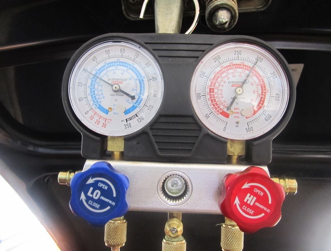
The system is now running- at 33C / RH70% it was running 24 psig on the inlet and close to 300 psig on the HP side. I filled it with 1kg of R134 but there is some tolerance on the actual amount given the limits of the scale I used. The vent temp was 14C on my driveway but I suspect that will drop some on the road and with time to come to full equilibrium. The humidity obviously takes its toll [on both the ac and myself]..
Have to finish a few bits and pieces to be able to take it for a test drive.
OK for boxed the thing up this afternoon and took it for a test drive- similar condition to what I reported yesterday [33C/ 70% RH- it was cloudy!]. Cruising at 2000 rpm the temperature dropped to 9.5C and at 2500 rpm it dropped to 8C. Further revs did not seem to make any difference but I have to be careful as the radar traps are everywhere these days. The cabin felt nice and cool but also had it part striped out -passenger seat, carpets etc still out. The floor pan on the passenger side was rather warm! Still the car felt nice and cool.
I checked the footwell flap- my actuator packed up a few years ago and as a temporary measure I tried to force it such that fresh air has to be admitted via the windows! There was a little bit of movement of the trap door so my result may be skewed a little due to admittance of some fresh air- maybe a good thing! The ac performance felt better than it has since my enforced conversion to 134..
I still want to clean the evaporator if possible- I have one of those spray cleaners if I can get it in there. My blower is also making strange noises at times so maybe I will pull the blower and see if I can fix the actuator at the same time- that should permit me to get superior access to the evaporator matrix with that rubber connector out of the way. To change the blower out I suspect the easiest way is to remove the bonnet. I believe it can be done with the bonnet in place but it seems as though it would be a right PITA!
Regarding performance I did a bit of checking and given my ambient temps and humidity I reckon it is not doing too bad - not brilliant but not bad either. To put things into persepective I gathered some data and considering a starting temperature of 30C and a final temperature of 10C for dry air the enthalpy change would be 20 kJ/Kg [enthalpy is a measure of heat content wherein the reference point is dry air at zero C has an enthalpy of zero kj/kg] . For fully saturated air over the same temperature range the enthalpy change would be 70 kJ/Kg. In other words 3.5 times the heat load. Amend those numbers to reflect my ambient conditions and my system would have to lose 50kJ/Kg which over twice that of dry air. Put another way, if dry air at the same temperature was losing heat at the same rate it would be below freezing point. In practice the freeze switch kicks in just above freezing point [1 degree C?], the lowest temperature you can get is controlled by the practical approach temperature which will be about 3 degrees C above the evaporator body temperature so the with the freeze switch operating the lowest temperature you are going to see with dry air will be about 4C.therefore I would conclude that my 8C today in 60% humidity 33C temperature is probably OK.
The problem I have with the 134 charts is that I do not believe them or more specifically I do not buy into the LP chart that shows pressure dropping with increasing temperature.
The HP curve looks fine and sensible and as can be expected shows higher pressures than R12 and that is what I experienced before and now. With a 33 C ambient I saw about 240 psig [ 16.5 barg at 2k rpms].
The LP curve I find to be technically preposterous- static pressure is controlled by ambient conditions and the higher the ambient the higher the LP and HP pressures should be. This is what we see on the R12 curves but not on the 134 curve and therein I have a problem. If someone can explain that I am happy to listen but unless Charles's law has changed this does not make sense [unless Trump has revoked that as well!].
When I checked my system against the R12 curves when I was operating on such it all agreed quite nicely. Since I changed to R134 it has never aligned with those curves for LP and vent temps. Interesting that I am showing good agreement with the vent temps shown on the R12 curve.
As a general statement every opinion I have read regarding such conversion says that the system will be degraded slightly, this is what I experienced, so how can vent temperatures be as low as claimed on the R134 charts in the manual? The evaporator sensor cuts off the power to the clutch at 1 degree C, the approach temperature of the air passing over the evaporator can be no more than about 3 or 4 degrees C above the evaporator temperature so how can vent temps be less than 3 degrees C unless the temperature sensor is bypassed? To my way of thinking those 134 curves for LP and vent temp just do not make sense. As I am aware the GTS's that were kitted out with 134 have the same evaporators, condensers compressors and expansion valves so how could they possibly produce lower vent temperatures?
The system is designed around a specific volumetric flow, the mol weight of R12 is 121, the mol weight of R134 is 102 and thus the reduction in gas content by a factor of 0.843. Thus starting with the 1200 gms of R12 and applying that correction the number becomes 1011 gms. The WSM specifies 1050 gms and I restricted my fill to 1kg. My LP reading sows good agreement with the R12 curve, the vent temp shows good agreement with the R12 curve. The latent heat of evaporation of R134 is greater than that of R12 but whether the stock condenser can handle the additional heat load is my area of suspicion. I know that the condenser is limiting system performance and that I live in a coastal environment with typical RH values around 50% [often more].
r134a in a GTS. I have no idea what the system pressures were. And as we say in Texas (when I lived there as a boy and spoke 'Texan'): "don't care neither."
r134a in a GTS. I have no idea what the system pressures were. And as we say in Texas (when I lived there as a boy and spoke 'Texan'): "don't care neither."
Interesting- presumably the freeze switch was not working or bypassed? Was that reading taken in a location with low relative humidity? That thing would give you frost bite- it is nearly as cold as our deep freezer!
I am now wondering if my compressor is a bit tired. I need to be a bit more focussed on the low pressure reading at 2k rpms. The thing I noticed when cranking the compressor by hand to get the fresh oil moving a bit was the resistance was less than I might have expected- trouble is I do not really know just how such resistance should feel. All part of the learning curve.
Interesting- presumably the freeze switch was not working or bypassed? Was that reading taken in a location with low relative humidity? That thing would give you frost bite- it is nearly as cold as our deep freezer!
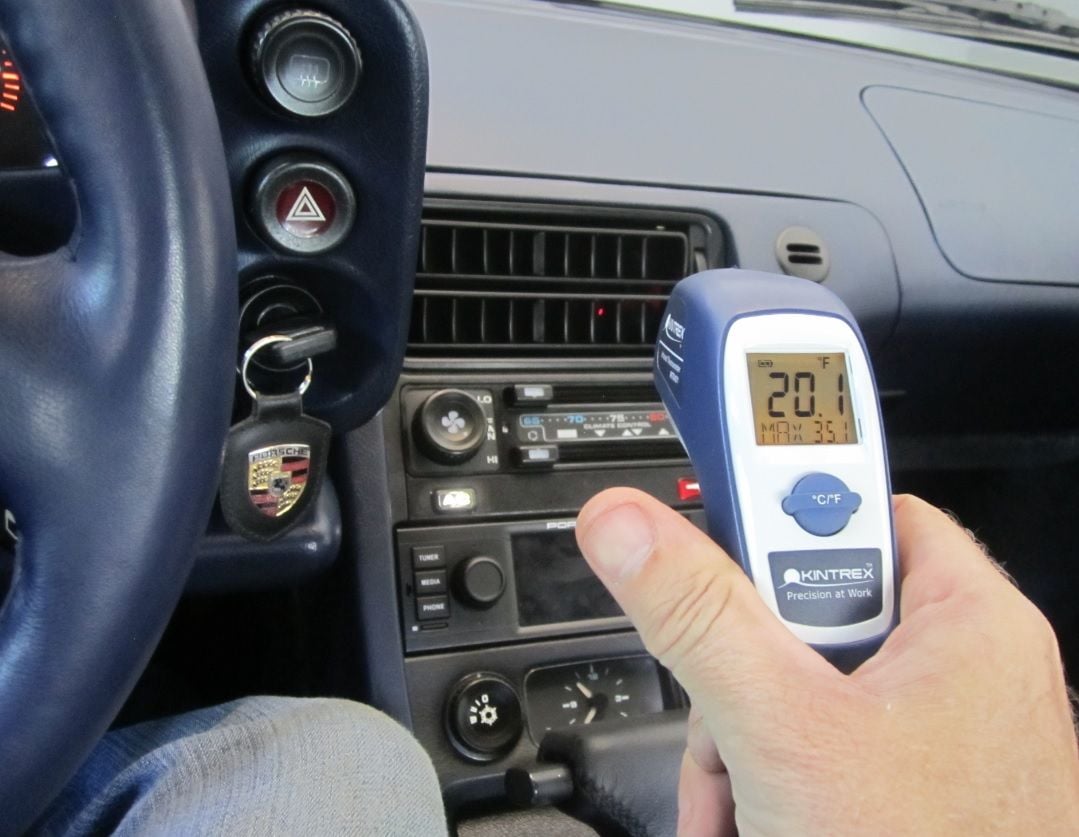
Freeze switch is brand new and calibrated. The GTS was up to temp, but had been off for about 30 minutes. The test was done at start-up. 60 degrees (F) and basically no humidity. Thus, the evaporator didn't get a chance to freeze before I discontinued the test. I figured 12 F degrees was good enough to prove to the BaT crowd that the A/C was most-definitely working.
I'm not interested in expending time on the theoretical debate on Thermodynamics. If, at 2500 rpm (what WSM specs, IIRC), you can't 'get on the r134a chart' (or at least very close) you're not getting maximum performance. The OE 10PA20 compressor, in good health, with uncontaminated r134a refrigerant should easily pull the low side to 20 PSI which will result in sub-freezing temps. This ain't my first r134a rodeo; I've seen this multiple times.
(Note: I take no credit for that GTS's A/C system. It's all Doc Brown's 'fault.')
I am now wondering if my compressor is a bit tired. I need to be a bit more focussed on the low pressure reading at 2k rpms. The thing I noticed when cranking the compressor by hand to get the fresh oil moving a bit was the resistance was less than I might have expected- trouble is I do not really know just how such resistance should feel. All part of the learning curve.
The nose of the compressor should take moderate force to rotate. It should feel like a 'tight' bearing.
A tired compressor won't be able to get the low side into the chart. I don't know if you have the OE 10-cylinder compressor. I've seen a few of the various 'after-market' (not a 10PA20) replacement compressors that struggle to get below ~35 PSI when new.
Also, of course, any non-refrigerant gas in the system will tend to result in poorer low-side performance.
One or both may be your issue.
Originally Posted by NoVector
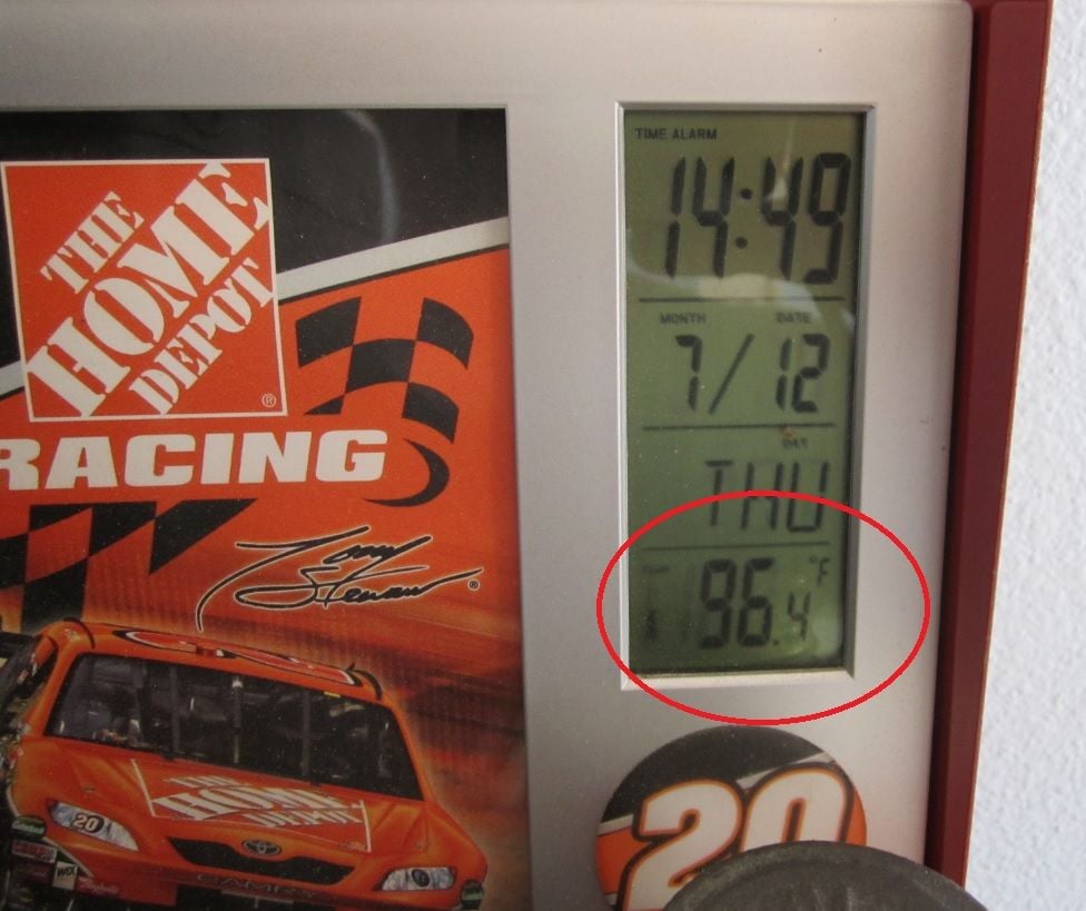
Here's mine, Fred, from last July after I replaced the compressor and both expansion valves. Humidity was probably ~80% and this is at idle.
I assume the gauge picture was at idle?
Originally Posted by Speedtoys
Try again with an A/C thermometer.
Not sure who you're talkin'to. But, yes, I usually use a contact thermometer. In this case I forgot it, and had to borrow the one shown. It's sufficient for the purpose, but I would assume it's not completely accurate. However, the A/C in that GTS was 'ball-freezing' cold. It did enable me to ensure that the auto-temperature control was working though.


 05-08-2019 | 08:52 AM