When you click on links to various merchants on this site and make a purchase, this can result in this site earning a commission. Affiliate programs and affiliations include, but are not limited to, the eBay Partner Network.
Does anyone have a simplified brake light wiring diagram (82ish)? The older wiring diagrams simply terminate the Stop Light switch (page 2, B8) at F6 F7. But but F6 F7 grid don't show anything regarding the brakes. So I don't know where the wiring picks back up. Additional the rear wiring traces from the brake bulb and disappears into the Check Bulb Computer.
Long story short, the other day, I went out for a night day and got the Stop Light warning about 20 minutes in. Both lights are out but the other tail lights work. If there is a common ground, this makes me think its not a rear ground but could be wrong. The fuse looks fine and has voltage on both sides. Then I checked the two pressure switches on the MC and both had voltage. I changed both pressure senders last night. Tonight I cleaned the connections at the Check Bulb connector and the two grounds above it.
I have searched all kinds of rennlist and pelican threads about brake lights and the check bulb setup. There's so much conflicting information. People swear the check bulb computer CANNOT make lights go out yet Porsche sells a connector to bypass the check bulb for testing,..,,
What do the two MC switches do? I assumed one was brake and one was pressure but other threads said they are both brake lights (so do they run in parallel or series???)
Can the check bulb computer crapping out cause a light to fail to light?
Does anyone have a simple explanation of the early brake wiring? Pressure switch to fuse to check bulb to bulb???
What exactly does the central informer do different than check bulb computer?
I just need to find where in the chain the signal is braking down.
AND of course now that I cleaned the check bulb and grounds, the headlights quit lighting...
The two switches on the M/cyl are connected to the warning light computer such that if one switch makes circuit and the other doesnt, the warning light latches and stays on until the battery is disconnected. They are cheap pressure operated units with an Audi/VW part no. They tend to clog up with fine debris from the fluid. I have been able to get brake lights working , without a warning, by just connecting the front switch, rear switch disconnected. Also on mine some previous mechanic had screwed the switch in with the electrical connector on it, so it was very badly and tightly twisted, which I think was shorting out the wiring. Check the fuses - I have had trouble with poor contacts on these crappy units, with bad contacts even producing sparks - fuel pump. I suggest re-tensioning the top fuse contact, and cleaning all contacts with deoxit. See my other thread at https://rennlist.com/forums/928-foru...e-sockets.html , scroll to pictures.
jp 83 Euro S AT 57k
Here is what you can do to jump connections and bypass the bulb check controller.
1. Jump one of the brake light switch connectors with ignition on. Terminals 81 to 82a or black/red to black wire.
2. Unplug the 12 pin connector at the bulb check controller. Test pin 1 to ground - this will be 12v from the jumpered brake light switch. If yes skip to step 5.
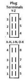
3. If you found no voltage in the step above, you have a break in the wiring since you said you did have voltage at the brake light switches. There are two terminals you can check at the CE panel. The black/red wire from the brake light switch runs to F7. The plugs at the bottom are labeled A through Z and this is how the terminals are numbered.
4. You should be able to test without unplugging by backprobing F7 to ground with your meter. Behind the CE panel is simply a jumper that runs to S6 and test here as well. The spade connectors sometimes push out the back of the panel and break connection. The wire out of S6 goes to pin 1 at the bulb check controller.
5. Jump pin 1 to pin 12 (brake lamp left) and pin 9 (brake lamp right). This will light up each brake lamp if the wiring, sockets, and bulbs are good.
If you do not have voltage at pin 1 but still want to test the rest of the brake lamp wiring you can jump pin 10 (fed from X bus, key on accessory position) to pin 12 and 9.
The two switches on the M/cyl are connected to the warning light computer such that if one switch makes circuit and the other doesnt, the warning light latches and stays on until the battery is disconnected. They are cheap pressure operated units with an Audi/VW part no. They tend to clog up with fine debris from the fluid. I have been able to get brake lights working , without a warning, by just connecting the front switch, rear switch disconnected. Also on mine some previous mechanic had screwed the switch in with the electrical connector on it, so it was very badly and tightly twisted, which I think was shorting out the wiring. Check the fuses - I have had trouble with poor contacts on these crappy units, with bad contacts even producing sparks - fuel pump. I suggest re-tensioning the top fuse contact, and cleaning all contacts with deoxit. See my other thread at https://rennlist.com/forums/928-foru...e-sockets.html , scroll to pictures.
jp 83 Euro S AT 57k
Thanks! I am heading to that thread. I've replaced the switches, deoxit the connectors, replaced the bulbs, deoxit the contacts, cleaned the fuse panel with deoxit, cleaned the grounds above the fuse panel. For an '82 my #10 fuse has power on both sides. The switch connectors have power on one side. The wiring diagram is worthless on what happens between the switch and the bulb computer.
The switches are wired parallel. This is the power flow from fuse to bulb.
MOOSE HANDS DOWN YOU GET THE PRIZE FOR MOST EPIC POST EVER. I've spent days looking for this. Is this expanded wiring diagram out of the service manual? The diagrams I have found do not have this much detail for wire/current flow path.
This is from the wiring diagrams in the 5 CD set from 928sRUS. It has the wiring for all years, service manuals with an index, and a ton of information on all of the systems.
This is from the wiring diagrams in the 5 CD set from 928sRUS. It has the wiring for all years, service manuals with an index, and a ton of information on all of the systems.
Here is what you can do to jump connections and bypass the bulb check controller.
1. Jump one of the brake light switch connectors with ignition on. Terminals 81 to 82a or black/red to black wire.
2. Unplug the 12 pin connector at the bulb check controller. Test pin 1 to ground - this will be 12v from the jumpered brake light switch. If yes skip to step 5.
3. If you found no voltage in the step above, you have a break in the wiring since you said you did have voltage at the brake light switches. There are two terminals you can check at the CE panel. The black/red wire from the brake light switch runs to F7. The plugs at the bottom are labeled A through Z and this is how the terminals are numbered.
4. You should be able to test without unplugging by backprobing F7 to ground with your meter. Behind the CE panel is simply a jumper that runs to S6 and test here as well. The spade connectors sometimes push out the back of the panel and break connection. The wire out of S6 goes to pin 1 at the bulb check controller.
5. Jump pin 1 to pin 12 (brake lamp left) and pin 9 (brake lamp right). This will light up each brake lamp if the wiring, sockets, and bulbs are good.
If you do not have voltage at pin 1 but still want to test the rest of the brake lamp wiring you can jump pin 10 (fed from X bus, key on accessory position) to pin 12 and 9.
1. Jumpered front pressure plug cause its the easiest
2. Fuse 10 -> 11v Bulb Check Pin 1 -> 9v
3. F7 -> 9v S6 -> 9v
4. Wires look good and seated
5. No lights but voltage at Pin 1, F7, S6 all drop to 0v when Pin 1 jumpered to 9 or 12 (load)
6. Jump Fuse 10 to Pin 9 or 12 -> brake lights light up
SO there's a pooor connection between the pressure switch plug and F7 somewhere. My 82 owner manual says brake is on fuse 10. '84 wiring diagram says fuse 7. I flipped over the fuse panel and there is no wiring propagating fuse 10 so I'm beginning to believe that the wiring (perhaps Weissach) better reflects an 83. Tomorrow I will trace out power on fuse 7.
Unfortunately there are a few inconsistencies in the manuals but the wiring diagrams are correct. Fuses 10 and 13 are spare positions. Brake lamps are fed from fuse 7.
If you rule out poor or loose connections you must have a nearly broken wire that flows voltage but cannot handle any load. By the way, what is your voltage at the jump post with engine off?
Do you have a test lamp that you can put some load at the brake lamp switches and see if it either lights or voltage drops to 0?
This is the correct chart.
This explains a lot. It took flipping the fuse panel over to see how crazy it is. To get through one fuse there are 4 connections which obviously adds a lot of problems and inconsistency to the power systems in these cars. On top of it all the back wiring is either white or black so there's no tracing it. I might pull the top fuse connectors for all inactive circuits to prevent confusion. I also labeled all the relays last night. It very well maybe just an issue at fuse 7 but I have been working to the front of 10 per my manual this hole time
Voltage at jump terminal is 12 so I'm already 1 v down at the fuse panel. I have a multimeter but I can created a lamp load with some wires and a brake bulb.
I would like to completely circumvent the brake light switches on the stock wiring harness. I do not have them on the car. A later master is now there. I do not have power at pin 1 even if I jumper the switches, but if I bring positive to the pins going to the brake lights and the driving lights, they do indeed light up. It would seem that I could wire a normal brake light switch to the brake pedal.
Does someone have a good pic of how it�s done on later cars? I don�t have one here with me.
Unfortunately there are a few inconsistencies in the manuals but the wiring diagrams are correct. Fuses 10 and 13 are spare positions. Brake lamps are fed from fuse 7.
Many thanks to Moose! I had a corroded connection on the back of Fuse 7 and this is one of those cases where newbie's need to get a full service manual since i spent days on wiring, switches, and fuse 10 since that's what the user manual chart showed.
Many thanks to Moose! I had a corroded connection on the back of Fuse 7 and this is one of those cases where newbie's need to get a full service manual since i spent days on wiring, switches, and fuse 10 since that's what the user manual chart showed.
Glad you found the problem.
Originally Posted by BC
I would like to completely circumvent the brake light switches on the stock wiring harness. I do not have them on the car. A later master is now there. I do not have power at pin 1 even if I jumper the switches, but if I bring positive to the pins going to the brake lights and the driving lights, they do indeed light up. It would seem that I could wire a normal brake light switch to the brake pedal.
Does someone have a good pic of how it�s done on later cars? I don�t have one here with me.
I can get a photo from my '89 tonight but this is from the manual.

 12-12-2018, 12:41 AM