
WTB: Flappy valve shaft plastic colllar
 11-20-2018, 03:35 PM
#16
Drifting
This small delay will give you plenty of time to clean and re-clean the intake to make sure it's absolutely clean and free from debris.
 11-20-2018, 03:41 PM
#17
Basic Sponsor
Rennlist
Site Sponsor
Rennlist
Site Sponsor
__________________

Does it have the "Do It Yourself" manual transmission, or the superior "Fully Equipped by Porsche" Automatic Transmission? George Layton March 2014
928 Owners are ".....a secret sect of quietly assured Porsche pragmatists who in near anonymity appreciate the prodigious, easy going prowess of the 928."
Does it have the "Do It Yourself" manual transmission, or the superior "Fully Equipped by Porsche" Automatic Transmission?
George Layton March 2014928 Owners are ".....a secret sect of quietly assured Porsche pragmatists who in near anonymity appreciate the prodigious, easy going prowess of the 928."
11-20-2018, 05:30 PM
#18
Rennlist Member

Ah, I see. They ride inside the spring, not the bore of the housing. What material will you use for this? I use PLA and ABS on my printer, but not sure if either of those will hold up to heat and fuel.
11-20-2018, 05:43 PM
#19

 . Looks like Rob is on the case.
Cool. Can you also verify that the #2 and the #7 spacers are identical like Luis stated?


Done. As soon as I get them check fit and verified by Luis (or Rob if Luis can't) I will put you first on the list.
11-20-2018, 05:56 PM
#20
Addict
Rennlist Member
Rennlist Member
Thread Starter
I can't absolutely verify that #2 and #7 are identical since I lost #2 but I can't envision how they would be different.
I won't have my intake back for maybe 2 or 3 weeks so any fitment test would have to wait until then, but I am happy to do it.
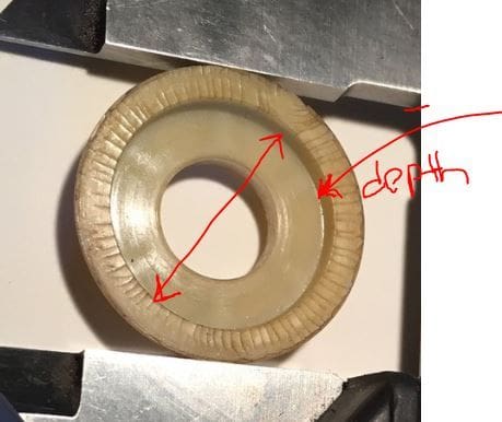
The depth I am missing in your annotated pic is 2.18mm and the inner diameter 19.30mm.
Regarding the ribbing in the back of the part, I imagine it's a way to make the part stiff while minimizing the amount of raw material utilized... The only other thing I can think of is that the small chambers can keep some oil in the rotating surfaces. To that end, I would just carve some channels with a dremel if the reproduced part ends up being flat in the back for production simplicity.
I won't have my intake back for maybe 2 or 3 weeks so any fitment test would have to wait until then, but I am happy to do it.
The depth I am missing in your annotated pic is 2.18mm and the inner diameter 19.30mm.
Regarding the ribbing in the back of the part, I imagine it's a way to make the part stiff while minimizing the amount of raw material utilized... The only other thing I can think of is that the small chambers can keep some oil in the rotating surfaces. To that end, I would just carve some channels with a dremel if the reproduced part ends up being flat in the back for production simplicity.
11-20-2018, 07:03 PM
#21
 11-20-2018, 07:28 PM
#22
I can't absolutely verify that #2 and #7 are identical since I lost #2 but I can't envision how they would be different.
I won't have my intake back for maybe 2 or 3 weeks so any fitment test would have to wait until then, but I am happy to do it.
The depth I am missing in your annotated pic is 2.18mm and the inner diameter 19.30mm.
Regarding the ribbing in the back of the part, I imagine it's a way to make the part stiff while minimizing the amount of raw material utilized... The only other thing I can think of is that the small chambers can keep some oil in the rotating surfaces. To that end, I would just carve some channels with a dremel if the reproduced part ends up being flat in the back for production simplicity.
11-20-2018, 08:17 PM
#24
 11-26-2018, 08:47 AM
#28
 11-26-2018, 10:52 AM
#29
Archive Gatekeeper
Rennlist Member
Rennlist Member
Shaft OD- 9.97 mm.
