

Rod side clearance


Thread Starter
Rennlist Member

Joined: Dec 2001
Posts: 25,186
Likes: 105
Rennlist Member
Joined: Feb 2011
Posts: 2,343
Likes: 699
From: Mostly in my workshop located in Sweden.
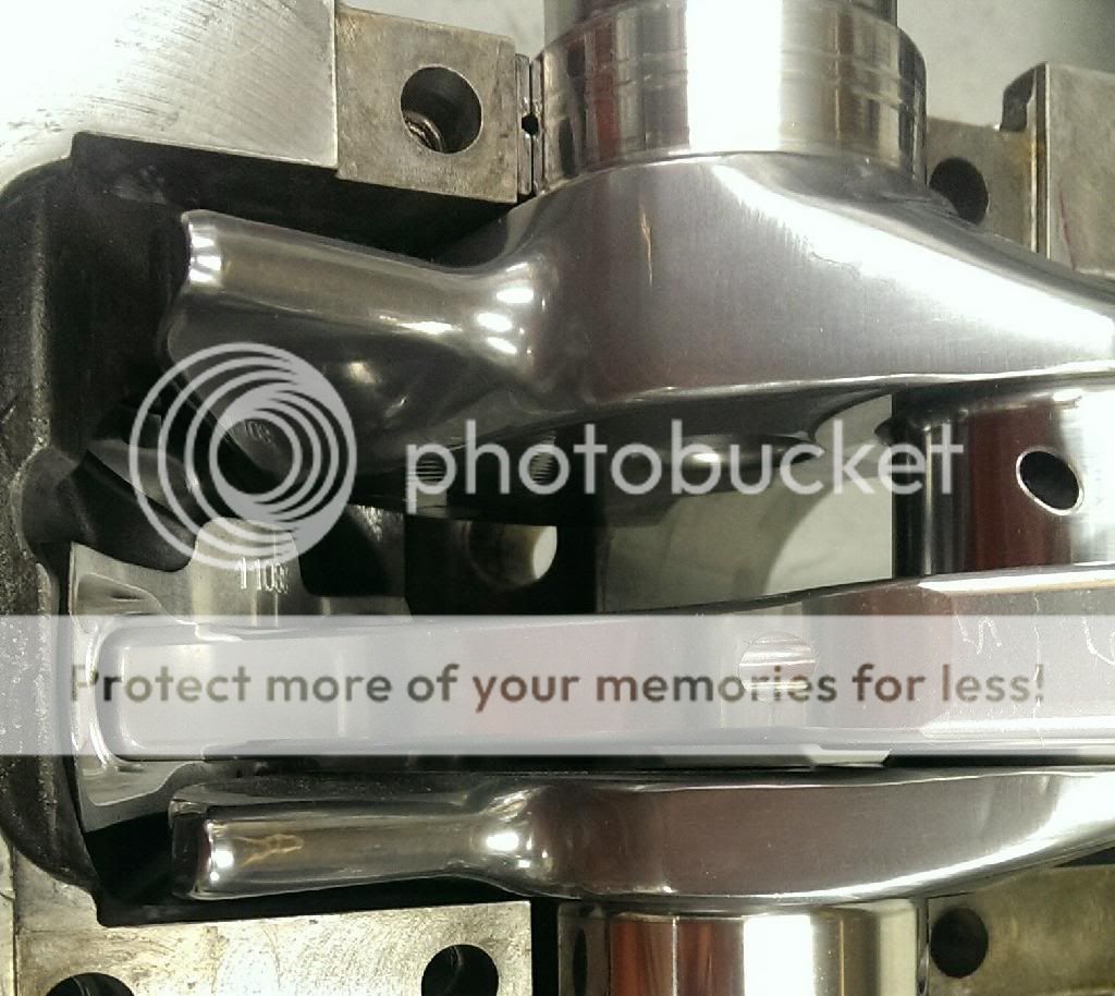
The 928 engine do have crankshaft guided rods. The 928 rod side clearance should be between 0,08 to 0,24mm or .0031" to .0094". For older engines the clearance is prescribe to be slightly larger 0,20 to 0,40mm. Some engines like my wifes old Volvo (the B230 engine) have piston guided rods where the side clearance is at the crankshaft is considerably larger.
Rennlist Member
Joined: Feb 2011
Posts: 2,343
Likes: 699
From: Mostly in my workshop located in Sweden.
Inspect/Service
NOTENot all do-it-yourself customers will have the tools needed to perform this procedure. Consider going to a machine shop to have this job done.Reconditioning A Connecting Rod
A connecting rod can often be reconditioned. The following procedures may need to be performed on a connecting rod before its returned to service:
- Replace rod bolts.
- Straightening.
- Resizing the big-end bore.
- Resizing the small-end bore.
- Installing bushings into the small-end bore.
- Beaming.
Cap Bolt Replacement
It is a good practice to replace the connecting bolts whenever the rods are removed from the engine. It the big-end bore requires reconditioning, the bolts will have to be removed to perform some of the machining operations. However, if the rod requires straightening, straighten the rod before replacing the bolts.
Most connecting rod bolts are press-fit into the connecting rod. It is best to press both bolts out at the same time instead of attempting to knock them out with a hammer. They should come out with little pressure. If excessive pressure is required, back off the press ram. Continuing to increase pressure may break or bend the connecting rod. Use a connecting rod heater to heat the rod and try pressing the bolts out again.
After the caps and rods are machined, new bolts can be installed. When installing the bolts, it is important to protect the parting surface of the rod. A fixture can be made or purchased for installing the bolts. With the rod located over the fixture, the bolts can be seated with a punch or hammer.
Using an installation to press in the new rod bolts protects the parting surface. Courtesy of K-Line Industries, Inc.CAUTION
Wear approved eye protection when performing this task. Do not stand in front of the connecting rod. Stand to the side.
Straightening Connecting Rods
If the inspection of the rod indicates it is bent or twisted, it may be possible to straighten it out. One method of correcting bend and twist is cold bending. This can be manually performed using a special holding fixture. When performing this procedure, it is important not to nick or scratch the rod. Nicks and scratches weaken the connecting rod and may lead to possible breakage.
Begin by determining the direction of bend or twist. Most bends in the rod will be located near the small-end bore. Place the connecting rod into the straightening fixture using the correct size big-end and small-end adapters. Install the cap and torque the cap bolts to specifications. Select the correct size bending bar. It should closely fit the rod to prevent nicks and scratches. Use the bar to bend the rod in small increments. Measure the progress on a rod alignment fixture.
Resizing the Big-End Bore
Big-end bores can be reconditioned using two methods: oversizing the bore or returning the bore to original size. The method used depends on the amount of wear and damage in the bore.
CAUTION
Always wear approved eye protection when grinding the caps and rods.
If it is determined that the bore is to be returned to its original size, grind the parting surfaces of the rod and cap to make the vertical diameter of the bore about 0.002 in. (0.050 mm) smaller. When grinding the parting surface of the rod, remove only enough material to restore the surface.
The procedures for removing material from the cap and rod are the same.
- First, remove the cap bolts.
- Place the workpiece in the grinder so it is resting on the squaring rod.
- Tighten the machine's vise to secure the workpiece.
- It is important that the workpiece be secured so the grinding wheel removes an even amount from both ends. If unequal amounts are removed, the cap and rod will not be square.
- Back off the feed wheel to be sure the grinding wheel will not contact the workpiece at this time.
- Position the workpiece over the grinding wheel and adjust the feed wheel until the parting surface just comes into contact with the stone.
- Swing the workpiece out of the way.
- Turn on the motor and swing the workpiece over the grinding wheel. This is the zero cut.
- Adjust the feed wheel to remove 0.002 inch (0.050 mm) and take another pass over the stone with the workpiece.
- If more metal must be removed, adjust the feed wheel to the desired amount and swing the cap over the stone.
- Do not remove more than 0.002 in. (0.050 mm) at a time.
- Then install the connecting rod cap and torque it to the specified value.
- To keep the cap and rod assembly straight, use a rod vise when installing the cap.
- Use a dial bore gauge to determine how much material must be honed.
- Then select the honing mandrel that fits the bore diameter.
- Install the mandrel to the machine and test the feed of the stones by turning the machine on and adjusting the feed back and forth.
- The stones should go in and out.
- Set the spindle speed.
- If the bore diameter is over 2 in. (50 mm), the speed should be set to 200 rpm. Next, set the cutting pressure. On many machines, use a dial setting of 2 for rough honing and 1 to finish hone the bore.
- Then rotate the spindle until the mandrel shoes are facing up and loosen the clamp that secures the shoes.
- Place a connecting rod onto the mandrel. Depress the foot pedal and adjust the feed dial until the shoes expand and lock the rod in place.
- Retighten the shoe clamp screw, then back off the feed until the dial indicator reads zero.
- This provides a zero set to determine how much the bore is being honed.
- Adjust the torque rod to support the flat surface of the rod as close to the small-end bore as possible.
- Adjust the coolant flow over the workpiece. Use the foot pedal to control the machine.
- Stroke the rod the entire length of the stones while maintaining stone pressure by turning the feed dial. Observe the honing dial to measure the amount of material removed.
- Use a slower speed to provide a smooth finish. Do not use any additional stone pressure. After the bore has been resized, measure the bore diameter.
Honing two connecting rods at the same time helps to keep the bores square. The two rods are held next to each other during the honing operation.It is recommended that the bores be rechamfered to restore the original oil throw-off properties. Remember these considerations when reconditioning the big-end bore:
- Attempt to remove most of the metal from the rod cap instead of the rod.
- Removing metal from the rod reduces the center-to-center distance of the rod and the compression ratio of the cylinder
- The center-to-center distance between rods should not vary more than 0.010 in. (0.254 mm).
Always wear approved eye protection when honing the connecting rod bore.
- If returning the bores to their original size will result in excessive center-to-center length reduction, it may be possible to bore or hone the big-end bore to accept an oversized bearing. This can be done only if oversized bearings are available.
The reconditioning method used on small-end bores depends upon the type of piston pin fit. Press-fit piston pins require about 0.001 in. (0.025 mm) interference. If the bore is worn, it will need to be resized to accept an oversized pin. This will require the pin boss in the piston to be oversized as well. Before performing this operation, be sure to weigh the cost of replacement versus the labor cost involved.
CAUTION
Always wear approved eye protection when performing this operation. Do now wear jewelry and make sure you do not have any loose clothing.
- Full-floating piston pins ride in a bushing pressed into the small-end bore.
- This bushing should be replaced as a matter of common practice whenever the engine is being rebuilt.
- Press out the old bushing using an adapter to prevent damage to the connecting rod.
- Press the new bushing into the bore, making sure any oil holes in the rod and bushing align to each other.
- If the bushing uses parting lines or slots to direct oil flow, it is sized to the pin.
- The first step is to expand the bushing using an expander bit.
- This seats the bushing into the bore.
- If this process is not done, proper heat transfer will not occur.
- To expand the bushing, select the correct size mandrel for the bushing.
- Set the spindle speed to 200 rpm and rotate the pressure-setting dial all of the way off.
- Locate the small-end bore over the mandrel.
- Direct the coolant flow into the workpiece.
- Use the foot pedal to start the spindle and stroke the connecting rod.
- Remove the rod and inspect the work.
- Next, use the facing cutter to remove any material from the outside of the bore.
- Finally, hone the bushings to fit the pin. The clearance is usually between 0.0003 and 0.0005 in. (0.008 and 0.013 mm).
- To do this procedure, start by determining the amount to be honed from each bushing.
- Adjust the pressure setting to 1 and follow the same procedure for expanding the bushing to hone the bushing to final size.
- Check piston pin fit on each bushing. If a bushing is too loose, remove it and install a new one.
When all the pistons and rods have been installed, connecting rod side clearance can be measured.

Measuring connecting rod side clearance.
- Side clearance is the amount of clearance between the crankshaft and the side of the connecting rod.
- Side clearance is measured with a feeler gauge.
- If the clearance is not correct, the rods may have to be machined or replaced.
- A rod suspected of being twisted can be checked on a rod aligning fixture and straightened as needed.

Checking connecting rod alignment. Courtesy of Sunnen Products Company, St. Louis, Missouri.
- The figure below shows the difference between bent and twisted rods and how each can be corrected.
Correcting rod twist and bend. Courtesy of Sunnen Products Company, St. Louis, Missouri.Measuring Connecting Rod "Out-of-Round"
When a rod bearing has "spun" or burned or if the big end of the connecting rod has "stretched," the rod can be resized.
Rod stretch sometimes causes the rod to draw closer together at the rod cap parting line. This sometimes causes bearing wear at the ends of the inserts.
Rod stretch causes bearing wear at the parting line. Courtesy of AE Clevite Engine Parts.Rods are measured for "out-of-round" with a special gauge.
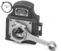
Checking for rod stretch. Courtesy of Sunnen Products Company, St. Louis, Missouri.The gauge measures in tenths of thousandths. usually, rods can be up to 0.001" out-of-round before resizing is necessary.
Connecting Rod Resize
When a rod bearing has spun or burned or if the big end of the connecting rod has "stretched," the rod can be resized by a machine shop.
To resize a rod:
- The pressed-fit rod bolts are pressed or pounded out.
- A small amount of metal (usually less than 0.002") will be ground off of both the rod and cap mating surface.
- The rod cap is reinstalled on the rod and the rod nuts are torqued.
Overtorque of rod bolts can cause them to fail during deceleration (when the load is on the bolt instead of on the rod).
- The rod bore (which is now smaller as a result of grinding) is honed out with a rod hone until the original diameter of the rod bore is reached.
Honing connecting rods to size. Courtesy of Sunnen Products Company, St. Louis, Missouri.To repair the small end of a full-floating type connecting rod, a bronze bushing is installed and the bore is then honed to the proper size.