When you click on links to various merchants on this site and make a purchase, this can result in this site earning a commission. Affiliate programs and affiliations include, but are not limited to, the eBay Partner Network.
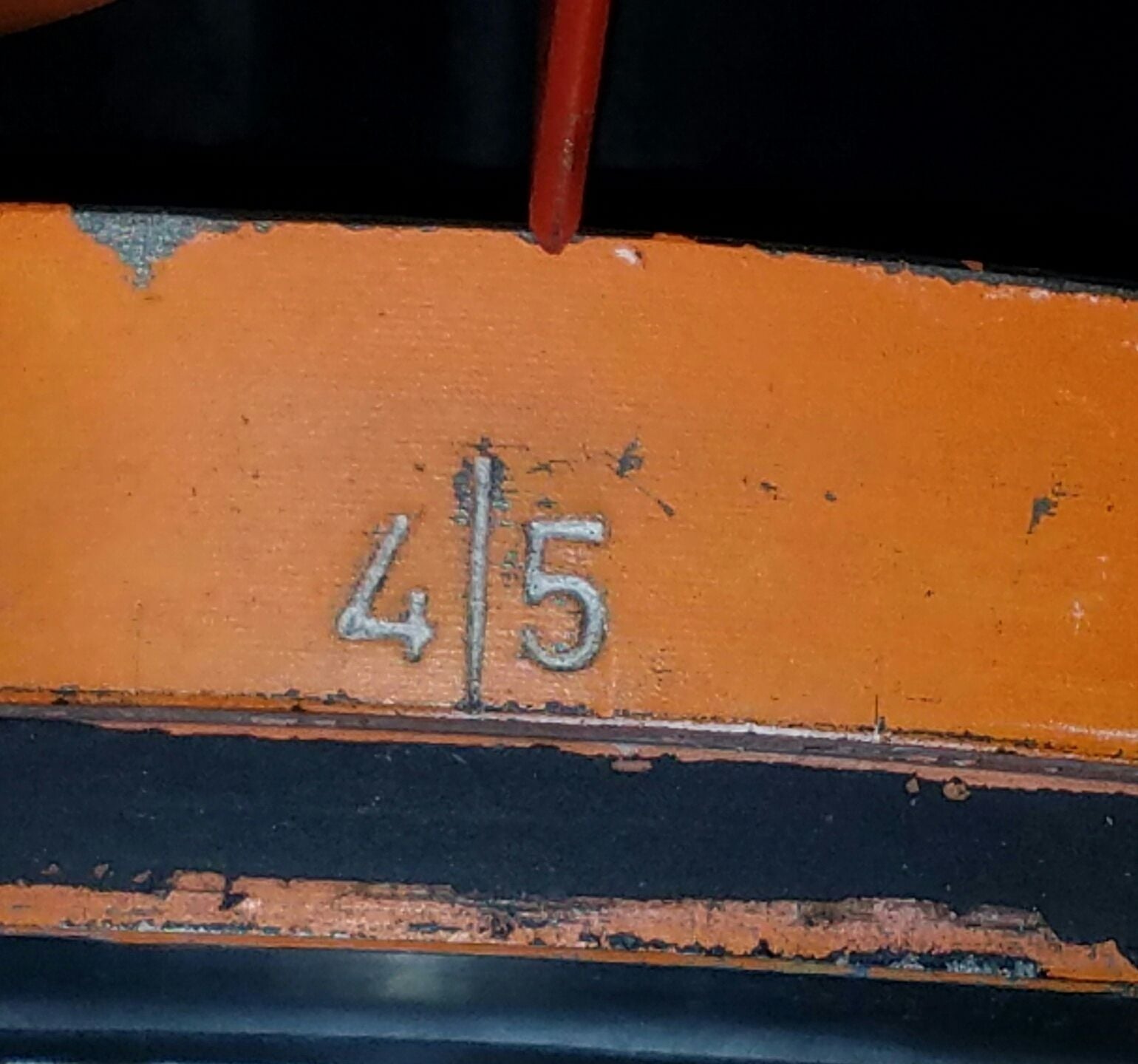
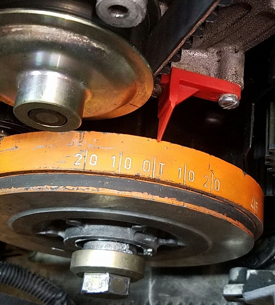
After putting in the timing belt and turning back the cam gears, the BTDC at 45* is a bit off with the flywheel lock still engaged.
I have attached some photos.
Is it ok or I need to redo my belt? I would appreciate any advise.
Again, Thank you.
The difference between the position pointer and the 45 BTDC mark is not relevant at this stage but when eventually timing the cams with your new 32VR tool the marks should be perfectly aligned as that difference might induce an error in the region of 1 degree [of the cam rotation] I would estimate.
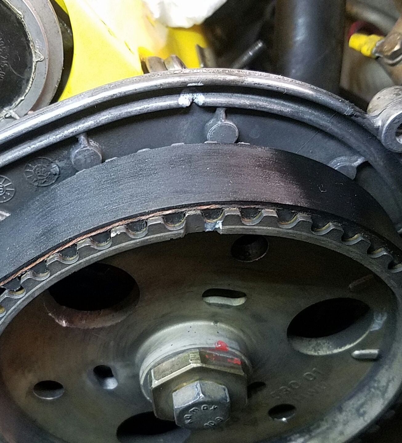
Presumably the picture of 1/4 cam sprocket shows the alignment marks it was previously set at and if so you should be "good to go" if that is the "comfort factor" you are looking for. What about the 5/8 bank?- that is just as critical.
The difference between the position pointer and the 45 BTDC mark is not relevant at this stage but when eventually timing the cams with your new 32VR tool the marks should be perfectly aligned as that difference might induce an error in the region of 1 degree [of the cam rotation] I would estimate.
Presumably the picture of 1/4 cam sprocket shows the alignment marks it was previously set at and if so you should be "good to go" if that is the "comfort factor" you are looking for. What about the 5/8 bank?- that is just as critical.
Thanks, FredR! Bank 5-8 is also included in the photos above but I will include here as well. They are lined up as well by the way.
So just to be sure, it's okay to take the flywheel lock off and check timing?
For your peace of mind you can count the number of cam teeth to where the position marks are are- they should be 24 teeth from where your paint marks are.
In your situation I would now remove the locking tool and forward the crank until at TDC on the other crank stroke then check the timing marks on the sprocket against the notch on the casing. They should more or less align.
Forward the crank in the direction of rotation using a long reach 27mm socket [or short extension] on the crank nut and then check the timing marks with No1 cylinder at TDC on its firing stroke. As you rotate the crank you will find varying degrees of resistance as the cams sequentially "bite and unload" - that is perfectly normal - [presumably you have done this already].
A bit of clarification because Im not sure what position marks are. Sorry but are they the ones on the cam gear? Or on the back plate cover?
Please note that my paint marks are 180* off as confirmed by GregBBRD. The white paint marks was done by the prior owner which threw me offwhen I set the locking tool
So do I put it on TDC and count the 24 teeth from there or at BTDC 45*? Thanks again!
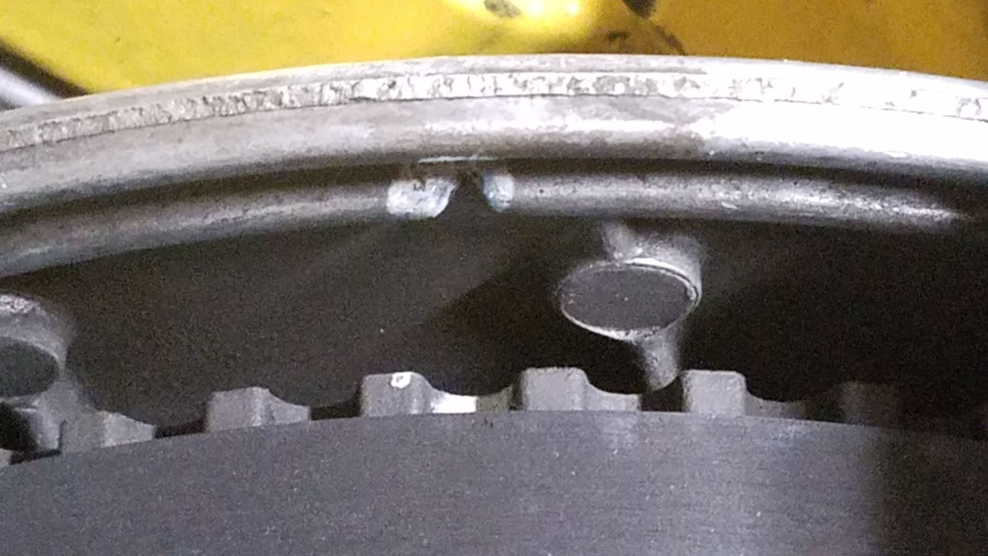
The cam sprockets have two marks- on the front face there is an indent about the width of one tooth and on the rear face there is a small slit or notch if you like. On the back plate cover there is also a notch and the cam sprocket rear notch should align with the casing notch at TDC No1 firing stroke.
The potentially confusing bit is where those timing marks on your cam sprocket are actually located. My assumption is that they were painted on by yourself when the crank was locked at 45 BTDC on the firing stroke for No 6 cylinder to give a reference mark for reassembly- correct? If so you should be able to see the front mark on the cam sprocket some 21 teeth clockwise or 27 teeth anti clockwise from the position you painted your marks. Your photos are too zoomed in to see the marks on your sprockets- suggest you take some pics that show the entire sprocket faces.
If you have any doubts do not move the crank until this is resolved. In part this is why we always recommend meaningful photos because trying to describe such in words, no matter how well written, leaves scope for misinterpretation whereas pics invariably speak for themselves when of appropriate quality.
To help you understand the details I have taken a pic of my previous 1/4 sprocket. You can see the machined mark on the front and the small paint mark I used to identify where the mark should be when my motor was locked at 45 BTDC.
On that photo I have also placed markers to show where your sprocket should be. The oblong sticky should be adjacent to the notch in the back case and the triangular sticky is where the sprocket should be relative to the cover notch when the engine is forwarded to TDC firing stroke No6 cylinder.
The other photo shows the indexing notch on the back of the sprocket.
Trust these help
Apologies but the system is not accepting my photos- will try later! Still not working- send me a PM with your email address and I will send you a copy of the image directly
Piling on again. With the crank locked at 45 btdc, you can rotate the cams to their normal marks for #1 before stringing the belt. The only difference between #1 and #6 is the cam position.
Get the camgear marks lined up as close as you can, being aware that you can easily be off up to half a tooth when looking at the marks. The actual gear position is a function of belt length between gears. When you use the 32VR to index the cams, the position of the gears relative to the heads doesn’t change. You will move the cams relative to the gears, which are locked to the crank by the belt.
The cam sprockets have two marks- on the front face there is an indent about the width of one tooth and on the rear face there is a small slit or notch if you like. On the back plate cover there is also a notch and the cam sprocket rear notch should align with the casing notch at TDC No1 firing stroke.
The potentially confusing bit is where those timing marks on your cam sprocket are actually located. My assumption is that they were painted on by yourself when the crank was locked at 45 BTDC on the firing stroke for No 6 cylinder to give a reference mark for reassembly- correct? If so you should be able to see the front mark on the cam sprocket some 21 teeth clockwise or 27 teeth anti clockwise from the position you painted your marks. Your photos are too zoomed in to see the marks on your sprockets- suggest you take some pics that show the entire sprocket faces.
If you have any doubts do not move the crank until this is resolved. In part this is why we always recommend meaningful photos because trying to describe such in words, no matter how well written, leaves scope for misinterpretation whereas pics invariably speak for themselves when of appropriate quality.
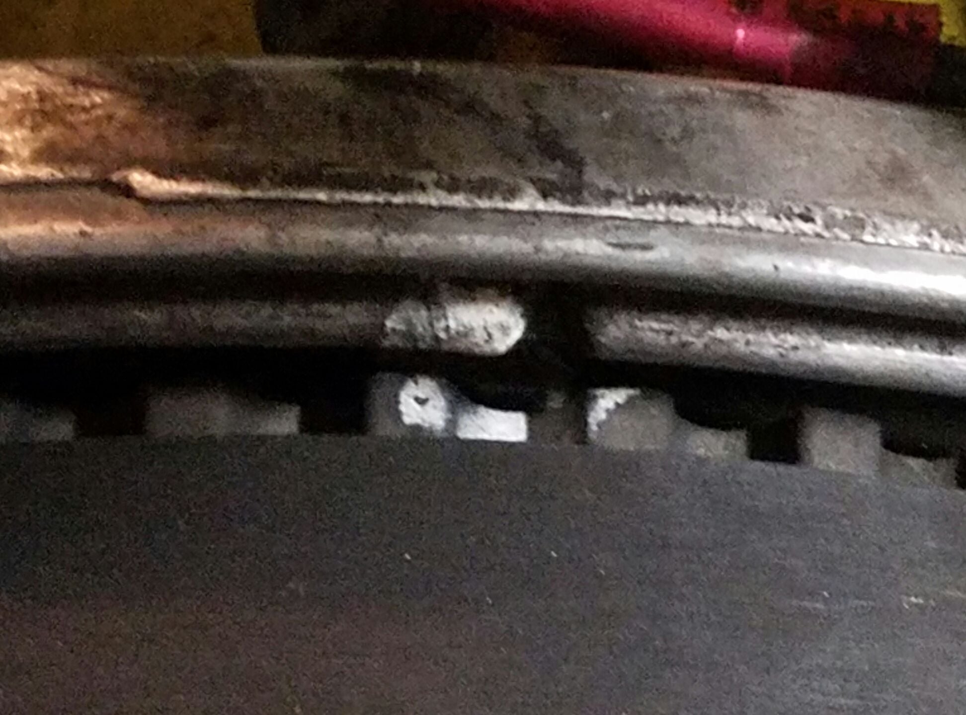
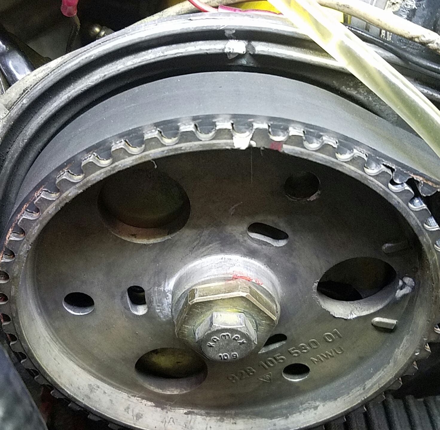
Yes, the white paint mark made on the back teeth of the sprocket (that matches the v groove on the back plate) is 21 teeth from the cam gear front mark on bank 5/8. Im including a photo. It is also 21 teeth with bank 1/4.
Yes, the white paint mark made on the back teeth of the sprocket (that matches the v groove on the back plate) is 21 teeth from the cam gear front mark on bank 5/8. Im including a photo. It is also 21 teeth with bank 1/4.
Looks like you are in good shape- cannot be too careful with these things.
Still cannot post the pics so sent them to you by email but it looks as though you do not need them.
I do not buy into the post about the belt being uni-directional -if it were it would surely have directional arrows all over the thing but "never say never"....?
I've never heard that about the belt being unidirectional either, although I'm pretty sure my OCD wouldn't have allowed me to install it such that I couldn't read the writing lol...
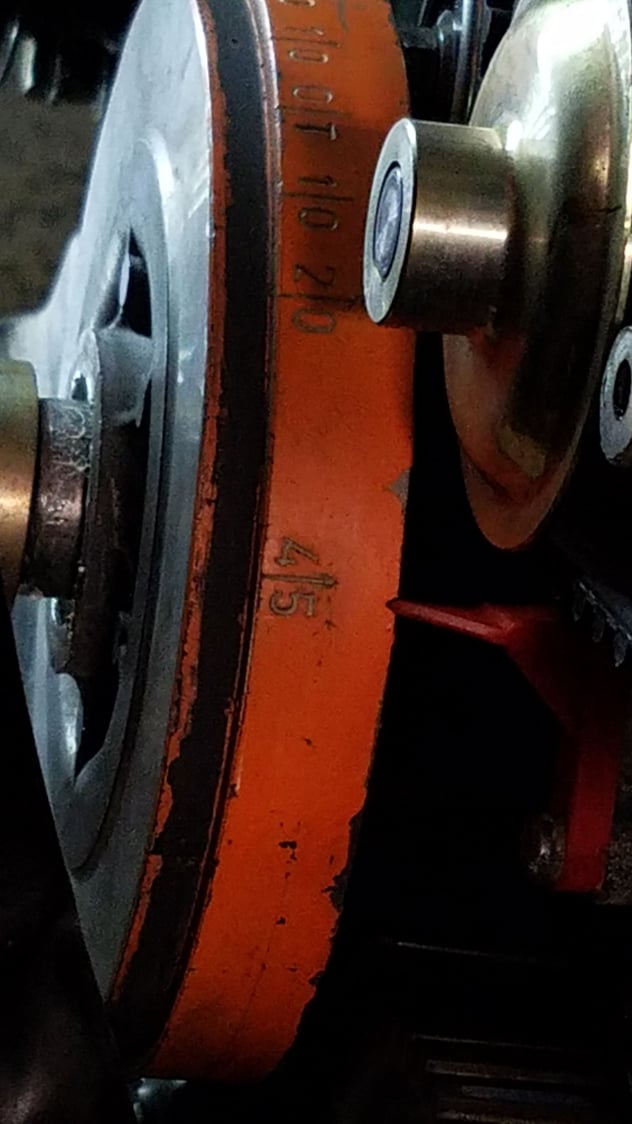
Looks like Im good at this point. Im back at 0T at TDC. Both Cam gears in sync with markers. Just waiting on Kempf tool and Porken timing tool to arrive tomorrow. Maybe my longest wait of the year. Thanks guys especially to GregBBRD and FredR!
In the meantime I'll be working on the flexplate, change the O2 sensor and if time permits replace the fuel filter. :-)

 10-18-2018, 02:10 AM