When you click on links to various merchants on this site and make a purchase, this can result in this site earning a commission. Affiliate programs and affiliations include, but are not limited to, the eBay Partner Network.
The input at the Powerdyne supercharger is 3.5" but the first 90 degree elbow is 3" at the opening with a welded adapter, so before it was essentially 3" and I'm running 3" pipe all the way to the duct intake, which is a 1"x7" opening. The previous K&N filter was big and open all the way around (not at the end), like maybe 8" long with a 4" diameter. Using just the pipe area, the 3" pipe x 3.141592 = 9.425 sq.in. using the 1"x7" oval as a rectangle would be 7 sq. in. so a little less surface area. This is part of the reason I was trying to do a dual intake setup, but couldn't swing it. I think I may try to use one of 928MS full width intake filters from the newer car setups and get the intake funnel connected to my sc input if I can figure out how to do that.
The input at the Powerdyne supercharger is 3.5" but the first 90 degree elbow is 3" at the opening with a welded adapter, so before it was essentially 3" and I'm running 3" pipe all the way to the duct intake, which is a 1"x7" opening. The previous K&N filter was big and open all the way around (not at the end), like maybe 8" long with a 4" diameter. Using just the pipe area, the 3" pipe x 3.141592 = 9.425 sq.in. using the 1"x7" oval as a rectangle would be 7 sq. in. so a little less surface area. This is part of the reason I was trying to do a dual intake setup, but couldn't swing it. I think I may try to use one of 928MS full width intake filters from the newer car setups and get the intake funnel connected to my sc input if I can figure out how to do that.
Hi Pete,
The cross sectional area of a 3" circular pipe is pi x radius squared. Not pi x diameter, which is the circumference. So using our 3" inlet pipe gives an area of 7.06 sq. inches, which is very comparable to your 1" x 7" opening. I agree more intake area is good, and asked Carl why he didn't use that full width intake design on the earlier cars. He said the distributor was the chief obstruction. Anyway, it's an interesting problem.
Good luck,
Dave
Right, thanks. Might try it again on a cooler and drier day to see if there's any difference. If it weren't for the boost gauge, I don't think I'd have been aware of any difference.
The intake diameter on my supercharger is 3.75 inches, and the intake to my airbox is 4 inch. That's about 11 sq inches for the intake and 12.5 sq inch for the airbox. The inlet area for my filter shroud is over 21.75 sq inches. The air filter area is 138.9 sq inches. Even with this much intake area and filter area I was restricting the air flow into the supercharger. I added an additional 2 in. diameter hose that goes around the side of the radiator with 4" cylinder air filter at the end. This seems to let the supercharger breath easily at full boost (15 psi), it was restricting the boost to 12.5 psi without the additional hose and filter. So intake area and filter size does effect the supercharger performance.
I have a write up on my air intake at http://928.jorj7.com/intake/
__________________
George
90 S4 Grand Prix White (Murf #5 - 210 mph top speed)
94 GTS 5-Speed Midnight Blue
06 Cayenne S Havanna/Sand Beige (PASM) http://928.jorj7.com
I really like your thinking, George. Thanks for posting.
Dave
I'm thinking about another concept. I've found a closed airbox that will fit in the area behind d the radiator. It would have a 4" inlet and I'd supply air to it from inside the left front fender. I'd drill a hole between the power steering reservoir and coil and screw in the 4" duct with mounting plate with a Frogskinz filter on it to prevent any water from entering. Plum to the duct with a 4" 45 degree elbow that would attach to the 4" inlet of the airbox, then to the 3" outlet on top, where I could just connect a 90 degree elbow to where the first red hose comes out of the supercharger inlet now. This would draw all the intake air from the fender and none from the engine bay. The airbox itself is 7" diameter and 7" tall with a 5" diameter, full height K&N filter inside of it. The company says its good to about 400 HP and I'm at 350.
If you guys think this seems like a decent setup that will resolve my current restriction and also eliminate the heat soak from sucking in air from behind the radiator, I'll order the parts and see how it goes.
Because the cold air intake has been provided through the radiator air damn, it might be just a simple thing to block off the hot radiator air from accessing the air filter. Just an air box. The access through the air dam to get cold air has already been provided. I used a long/tall air filter for longer service intervals - you could shorten it some so you could fit it into a air box. Just do NOT block air flow through the radiator with it!
Hi Pete,
I thought about going through the wheel well, but my intercooler heat exchanger is in the way.
Good luck,
Dave
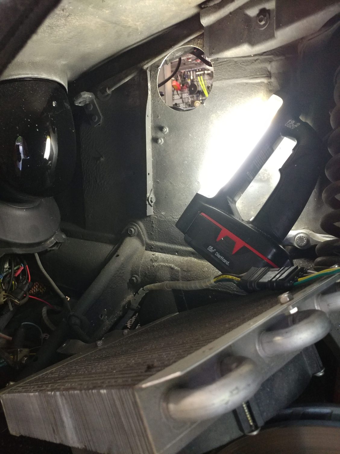
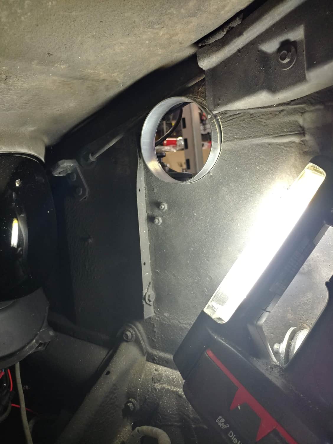
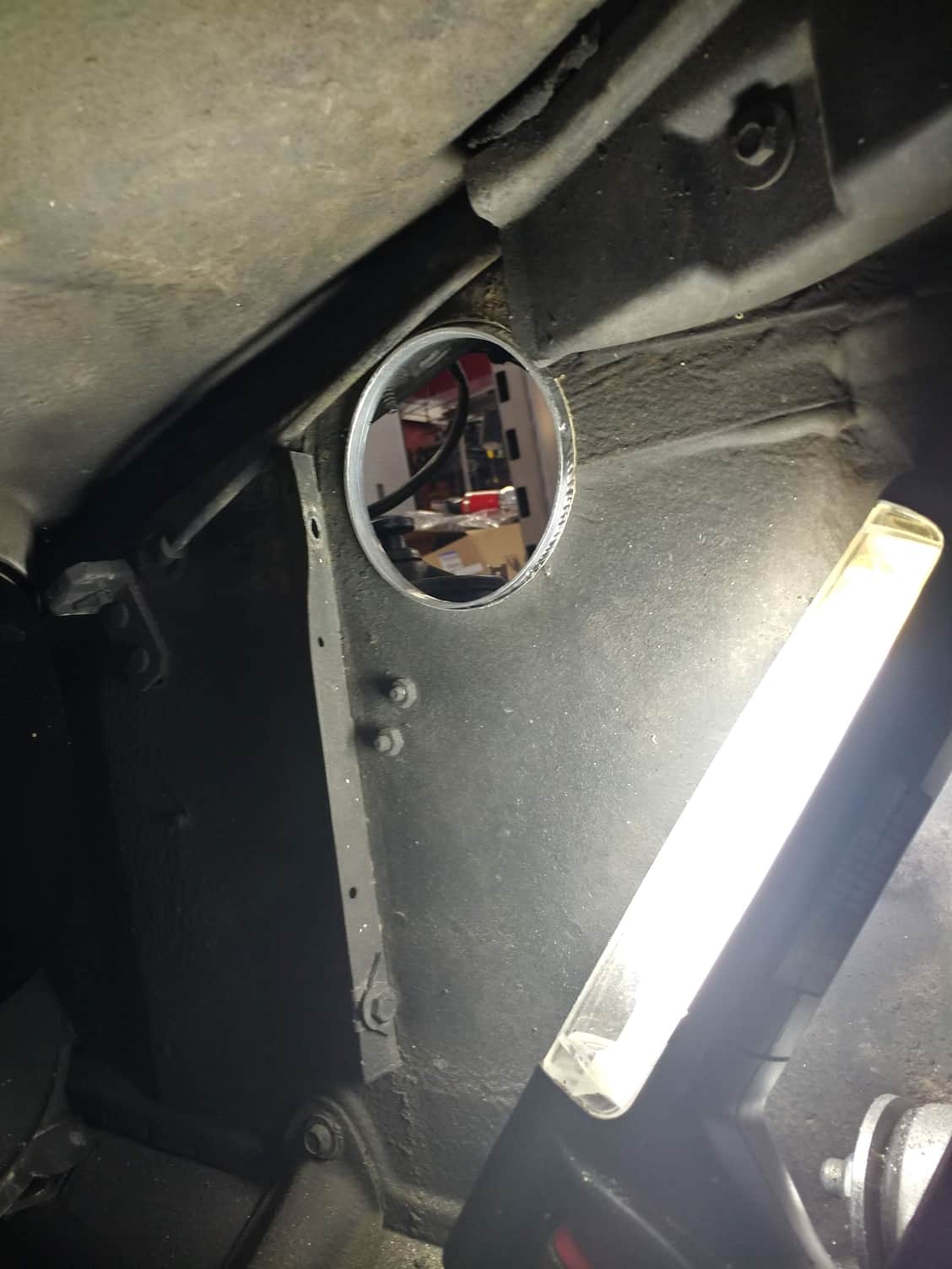
My intercooler is actually further forward. Back on the engine side, if I loosen the clamp on the coil and slide it a little further rearward in the bracket, I should have a nice 4" opening right there up near the top of that fender wall and a 45 degree elbow should then bend nicely around the power steering reservoir where I can connect the enclosed airbox. Back on the tire side, a Frogskinz filter sandwiched between the 2 mounting intake duct plates should keep the tire from spraying any water into the intake port (I don't have front fender liners). I think I'm going to give it a shot.
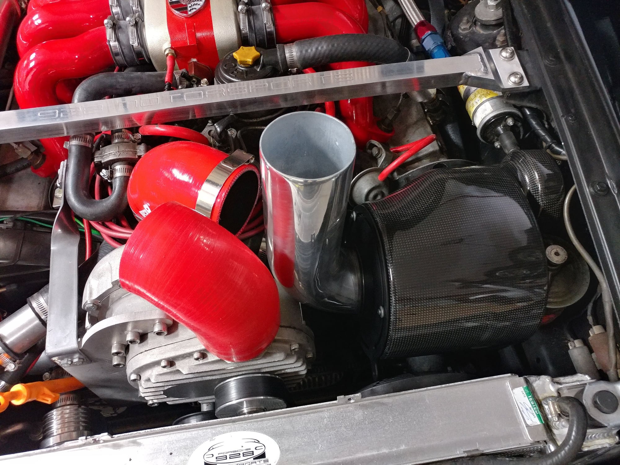
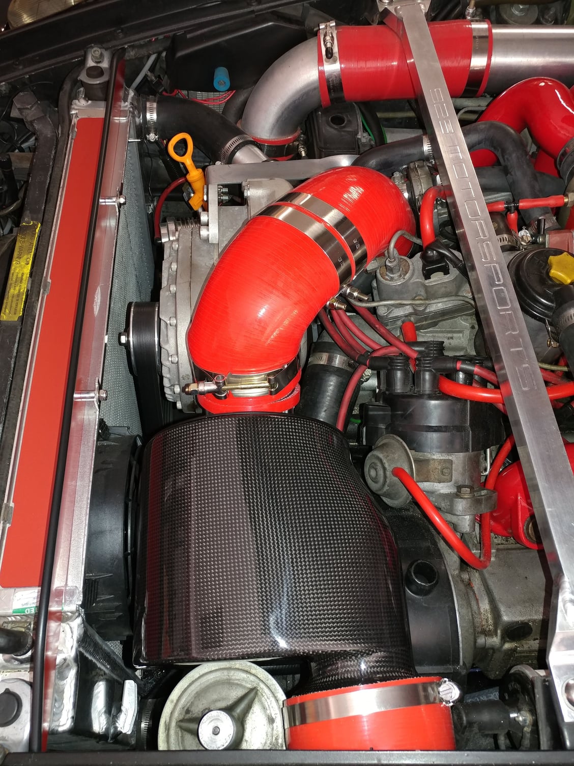
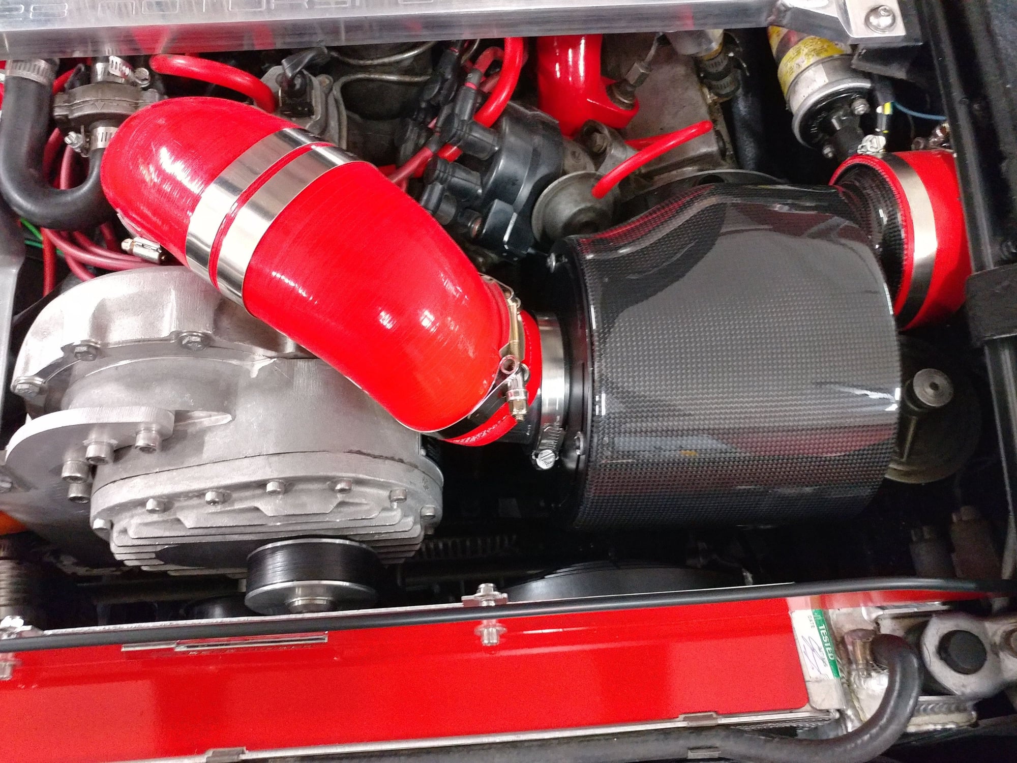
I've completed v3 of the cold air intake on my Spyder and was able to shoehorn it in as originally conceptualized. The airbox itself is a Carbonio TS model that's construction of Carbon Fiber - it's actually very well made and quite pretty.
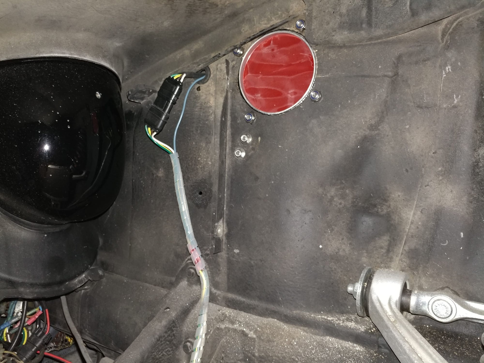
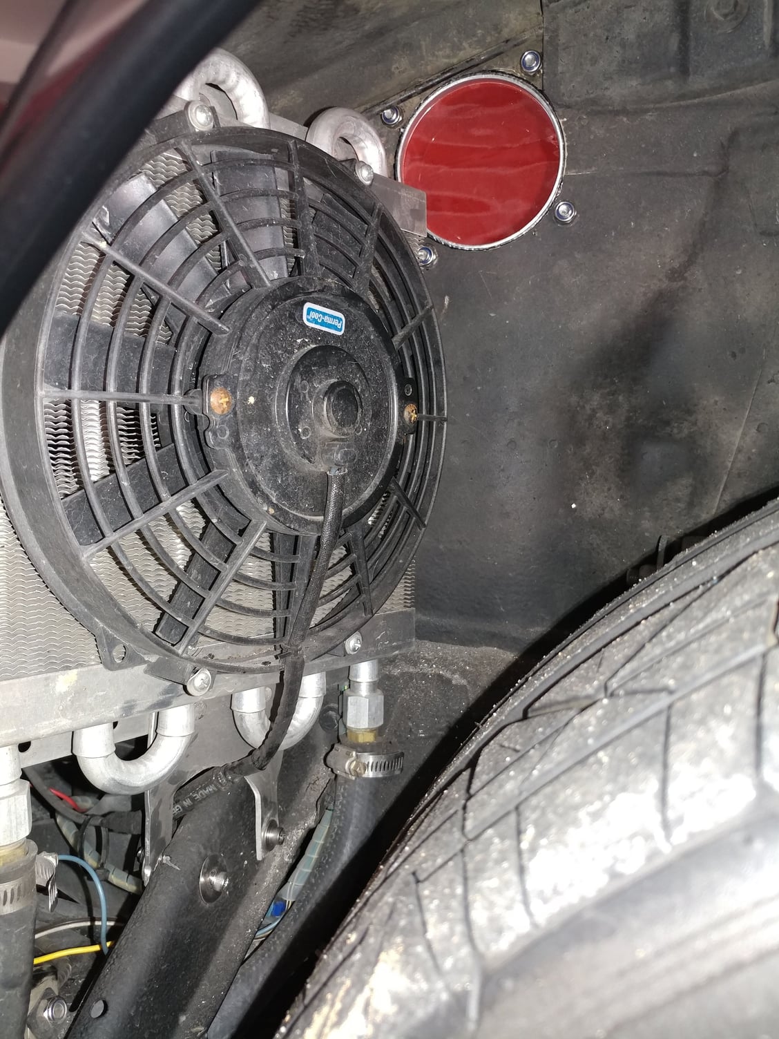
I loosened the clamp on the ignition coil and slid it forward in the mounting bracket a little bit to add some clearance.
I also had to relocate some wires I had run through the fender for lighting and accessories in the same area where the 4" intake hole would be located.
), trimming most of the flange off the one that was going to protrude through the wheelwell. I used 2 of them so that between the 2 flat sides I could sandwich in a layer of moisture barrier material. I bought a sheet of Frogzskin material that as a circle with 4" center section and a border outside of that, but my initial test of if where I peeled back the adhesive carrier and tried to blow through it showed it to be too restrictive, so I cut up the hydrophobic K&N prefilter I had around the K&N filter on my v1 intake and used that instead. Not sure how much it will do, but might shed some water and help to keep the primary filter in the airbox cleaner - we'll see
I then started fitting things together and mocking up how it would all go. I needed about 1/4" more space around the PS reservoir so enlarged the 2 fender mounting holes for that so I could slide it over away from the intake pipe a little to have things run straight.
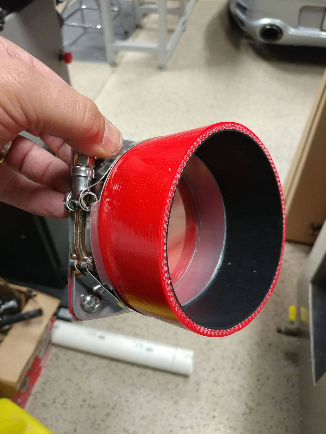
Then I cut a mandrel bent 90 degree Spectre polished aluminum pipe to go from the airbox up to connect to the other piping. I didn't change anything from the supercharger inlet to the first 90 degree silicone elbow from the v2 intake I made, just had to do the piping from the new airbox outlet to get it to connect to the first silicone 90 degree elbow that was there.
The straight section of pipe I cut off the metal elbow I used to make a connector piece to go between the 2 90 degree silicone elbows.
After putting it all together, I realized it was going to be a little too tall so I took the aluminum elbow connector piece back out and put that into my bench vise, turning it into a more oval shape instead of the round pipe - area should be the same and now I have a Hemi intake. Then did a similar thing with the aluminum 90 degree elbow that exits from the airbox to create a little more clearance between this elbow and the supercharger housing itself.
I had a thin circle I had trimmed from one of the silicone tubes when fabbing the v2 intake so I slipped that over the elbow to be a cushion and standoff between the metal 90 degree elbow and the supercharger
Because the airbox is also right up against the power steering reservoir lid, I took a circle of self-adhesive silicone sheet I had and crated a little pad at the contact area so vibrations wouldn't damage or wear through the lid of the airbox.
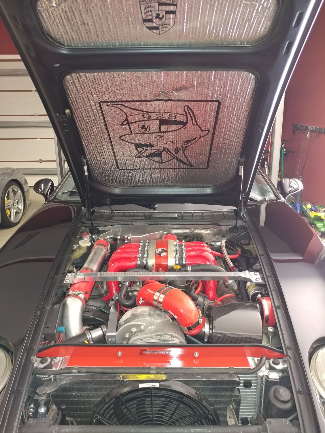
I fabricated a new block off plate that mounts above the radiator as now I don't need any openings in it anymore since the intake air is drawn in from the wheelwell - dressed it up a little with some red high-temp paint that matches the stripe on the intake Spider.
Here are pics of the process and finished product. I'll do another update after the first drive, but I think it turned out quite well and conceptually should prevent the supercharger from sucking in hot air that has come through the radiator, providing for more dense air and more power.
Drove the car with the new intake last night and it feels essentially the same as the v2, and the boost gauge is showing the same thing - usually up to 1.5 lines and if I held it full out past 5,000 RPM might move up to 2 lines, which I'm assuming is 0.2 bar or 2 lbs - still too low. Today I thought it about it further and decided that there's no way both the v2 and v3 intake setups are doing exactly the same thing so I had the thought that maybe the vacuum line that goes to the gauge somehow got crimped or something so tonight I took loose the front of the carpeted Plexiglas side panels I made (more on that in a minute), and lo and behold. wiggling the hard boost line that comes in and connects to the short section of silicone boost hose that then connects to the gauge, it completely came apart so it was either just barely connected or disconnected, but still maybe touching enough to register some boost and some vacuum, but I'm sure not providing accurate readings at all. I reinserted the hard line into the soft line and this time clamped the joint with the smallest clamp I had in the drawer, which seems to provide at least a little pressure. I'll drive it again tomorrow and see what kind of boost I'm getting, but I bet it's back to how I remember it, which also explains why the car didn't really feel any different from the v1 intake to the v2 intake to the v3 intake even though the boost gauge was showing a difference from v1 to v2/v3. I'll stick with the v3 intake setup as
I think the execution of the v3 is the best of the 3 with the greatest opportunity to suck in the most cool air and not experience any heat soak from behind the radiator as the carbon fiber airbox should be a worse conductor of any ambient heat that exists in that area from the radiator expelling heat than the aluminum Spectre housing would.
I also had to trim the length of the Spectre housing at the center joint in order to fit it into that area, so the point of the filter cone was probably a bit too close to the inlet aperture for optimal flow,
I have a lot more filter media in the larger cylindrical filter in the Carbonio airbox than I had in the smaller conical Spectre filter so longer service intervals and probably better filtering,
Carl also brought up a good point about air velocity through the filter and filtering efficacy, so I think this setup better protects the motor from particle debris
and, it's currently installed so I can leave it as is and move on to other projects.
Unfortunately, with the loose boost gauge hose connection, it means we didn't get any data about the v2 intake and whether that setup cost any boost due to air flow or capacity. I'll report back after the drive.


 05-20-2018, 07:19 PM