When you click on links to various merchants on this site and make a purchase, this can result in this site earning a commission. Affiliate programs and affiliations include, but are not limited to, the eBay Partner Network.
/\ /\
I agree with what Carl says above. On my L-jet I vented that hose to atmosphere and never once saw any oil drips to the ground. Nonetheless, when I was doing some other work, I decided that it would be nicer to vent the PVC hose to the front of the plenum, and that's how I have it now. Not sure I see any difference whatsoever.
Dave
The difference is: when the PCV hose is vented to atmosphere, the car may drop a quarter-sized stain on the pavement where it is parked as oil droplets coating the inside of the hose run down and drip out. When the PCV hose is routed into the air intake, this will not happen.
I'd love it if my car only dropped a quarter sized spot every now and then. Mine does more of a perpetual oil change from various places, with a complete one each Spring - the least of which is the vent line. I even mix in a little power steering fluid to give the collection in the drip tray a dab of color. Someday it will get fixed, but most of my time recently has been spent trying to finish up the custom Cayenne before the summer family vacation trips start.
I have all the parts to do the closed up cold air intake on hand too - need to work that into the schedule as well - probably after this Friday's excursion in the 928 to the Mitty race at Road Atlanta but before Sharks in the Mountains.
Carl,
I put a catch can in the driver front fender, the vent on the catch can has made an oily dripping mess.
Do I have a problem with the PCV valve? If I do the cold air intake, shere should I put the vent?
Carl,
I put a catch can in the driver front fender, the vent on the catch can has made an oily dripping mess.
Do I have a problem with the PCV valve? If I do the cold air intake, shere should I put the vent?
Rick
Hi Rick,
I know you asked Carl, but you could always vent your catch can back to the intake plenum. The cold air intake should not affect that.
Good luck,
Dave
Yes. There's a fitting front center on the spider plenum that was maybe used for something else (A/C speedup?) that has an angled 3/8" nipple. Thant's where I introduced the PVC output. It's about 5" straight in front of the Porsche emblem on the plenum.
Good luck,
Dave
Yes. There's a fitting front center on the spider plenum that was maybe used for something else (A/C speedup?) that has an angled 3/8" nipple. Thant's where I introduced the PVC output. It's about 5" straight in front of the Porsche emblem on the plenum.
Good luck,
Dave
If you look back at my engine photo in Post #6, are you talking about the brick red colored plastic fitting on the front of the intake? My crankcase vent doesn't connect there and all the inputs on that fitting are being used for other hoses, so I wonder if you have something else not connected as it should be, unless you added a Y fitting to one of those lines to make another input. I think the WUR connects here, but don't know about the other hoses.
I do know with my supercharger setup, I was pulling a lot of vacuum in one of the larger diameter hoses to the point where it was almost completely collapsing it. Carl had a great idea where I went to a hardware store and found the perfectly sized spring to just fit inside that hose, but be larger than the barbs at either end, and it now forces the hose to keep it's shape. As a side benefit, it also makes a slight whistle as you let off the full throttle pedal between gear changes and now sounds almost like a turbo blow-off valve or the sound a K&N filter makes as it rapidly returns to shape from sucking air through it. I can probably take some better pictures of the fitting and the hoses that run to it if it will help someone.
Carl,
I put a catch can in the driver front fender, the vent on the catch can has made an oily dripping mess.
Do I have a problem with the PCV valve? If I do the cold air intake, shere should I put the vent?
Rick
This comment makes me wonder if your crankcase vent has ever had a baffle installed. If it has, you would be able to see the edge of the aluminum plate under the vent cover.
Ah - if the supercharger was installed and the crankcase vent did not get our baffle plate installed, then an important step was skipped. Installing the oil baffle plate requires removal of the water bridge, installing the oil baffle plate, then re-installing the water bridge.
We have the "standard" oil baffle plate for most 16v cars to offer - and that is a pic of it I posted just above.
However, for supercharged 16v cars, we make a bigger/better oil baffle plate. Plus, the supercharged 16v motor gets its own set of PCV modifications too.
These were in your original supercharger kit installation instructions and may not have been done. No worries, I have more if you lost them in the move
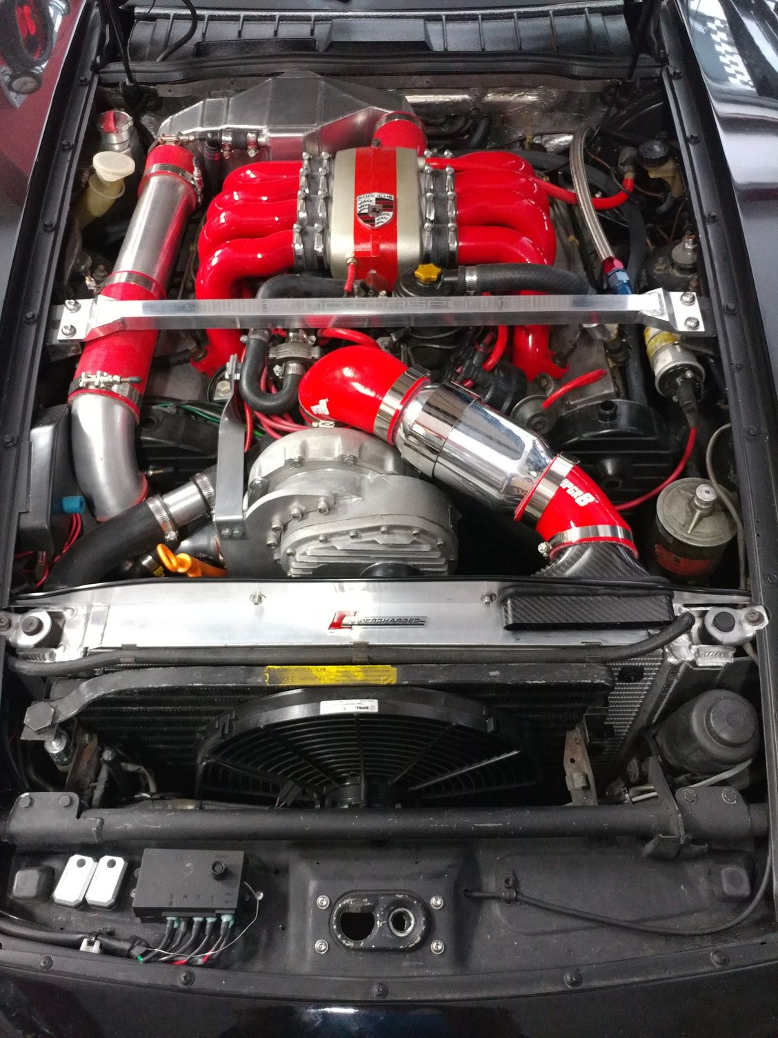
Over the past few days I've been working on this CAI for my 928MS supercharged 928. Theory was to draw colder air from above the radiator rather than hot air from behind it.
My initial plan was to make a dual intake version with an inlet on both sides above the radiator coming together at a Y shaped plenum at the supercharger input, but there's just not enough room, either for hood clearance or length from above the radiator to the sc input.
What I ended up with is this
which looks nice and clean and should achieve the goal.
I took it on its first drive since installation this morning and it seems to run just fine. Power feels good, I think maybe there is less intake roar after 4,000 RPM, which is also nice, and in monitoring my wideband AFR, the mixture under almost all conditions ranges from 12 to 13.5 which seem like they're in the right range and totally safe.
However, what I did notice is that the boost needle doesn't seem to go up quite as high and also seems to sit steady at the top reading whereas I though with the other intake it would steadily climb, though slowly, as the RPMs continued to climb 4,000 to 4,500 to 5,000 etc.
So my question is: is the intake limiting the boost to a lower level even though the gauge doesn't show an excessively lean or rich condition occuring. Its also pretty hot and humid here today so its possible that the air just isn't very dense or dry and that's creating the boost limit.
im of the thinking that is not enough "intake" for your set up, especially at higher rpms. It would have to be pretty sensitive but u could find a vacuum gauge and measure the draw before the filter and other areas along the intake and find restrictions?.
im of the thinking that is not enough "intake" for your set up, especially at higher rpms. It would have to be pretty sensitive but u could find a vacuum gauge and measure the draw before the filter and other areas along the intake and find restrictions?.
Clean set up though!
^I'm going to agree with this.
What is the area of the intake funnel opening?
And how does it compare to the cross section area of the intake tube going into the supercharger?
I will guess it's smaller. You need more 'opening', but I have no clue how you are going to get it.
The intake diameter on my supercharger is 3.75 inches, and the intake to my airbox is 4 inch. That's about 11 sq inches for the intake and 12.5 sq inch for the airbox. The inlet area for my filter shroud is over 21.75 sq inches. The air filter area is 138.9 sq inches. Even with this much intake area and filter area I was restricting the air flow into the supercharger. I added an additional 2 in. diameter hose that goes around the side of the radiator with 4" cylinder air filter at the end. This seems to let the supercharger breath easily at full boost (15 psi), it was restricting the boost to 12.5 psi without the additional hose and filter. So intake area and filter size does effect the supercharger performance.
I have a write up on my air intake at http://928.jorj7.com/intake/
__________________
George
90 S4 Grand Prix White (Murf #5 - 210 mph top speed)
94 GTS 5-Speed Midnight Blue
06 Cayenne S Havanna/Sand Beige (PASM) http://928.jorj7.com
And how does it compare to the cross section area of the intake tube going into the supercharger?
I will guess it's smaller. You need more 'opening', but I have no clue how you are going to get it.
Hi Joe,
I can answer for my system which is similar to Pete's:
Supercharger inlet 3" diam = 7.06 sq. in.
filter tube holder 4" diam = 12.56 sq. in.
funnel inlet (stock) 5.5 x 1.5" = 8.25 sq. in.
This does not factor in filter, and air resistance, but for my configuration the cross section of the supercharger inlet is the smallest size.
Pete used a different intake funnel, so I cannot comment on his intake area.


 04-23-2018, 11:17 AM