Engine wiring harness route
#1
Rennlist Member
Thread Starter
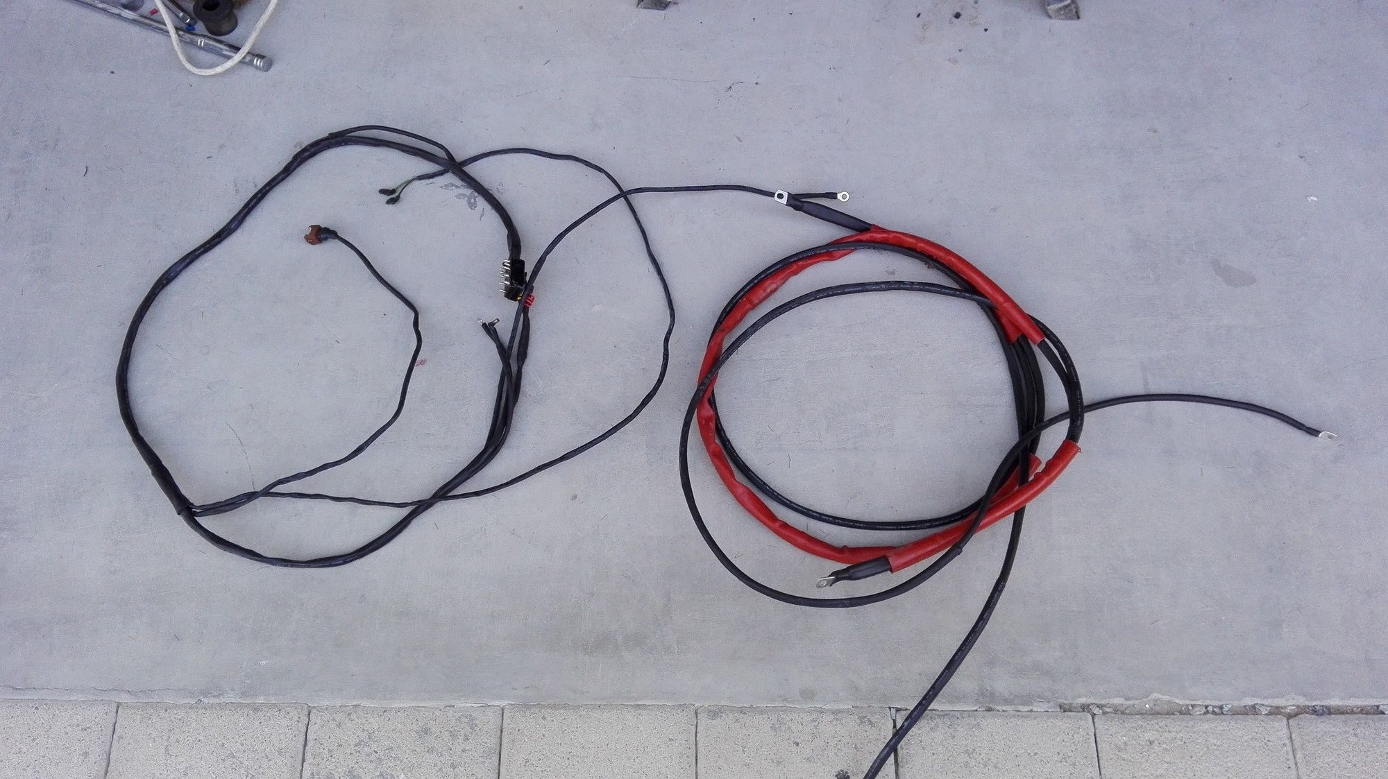
Just in the process of installing the new engine wiring harness I have made. Must have been half asleep when I removed the old one but I am struggling to visualise how to install the leg from the starter motor to the alternator. It looks as though it should cross over the top of the sub frame in the area adjacent to the gear box on the steering rack.
Guess I was so **** sure of my memory that I did not bother to take any pics before removing the old harness at that point!
Guess I was so **** sure of my memory that I did not bother to take any pics before removing the old harness at that point!
#2
Rennlist Member
It does go on top of the sub frame (through that Wire Loop) away from the exhaust, I use a pull wire to get it through that Loop.
You will need to remove that extra rubber sleeve and re-install it once it's pulled through, some WD-40 helps with that
Dave
You will need to remove that extra rubber sleeve and re-install it once it's pulled through, some WD-40 helps with that

Dave
#3
Rennlist Member
Thread Starter
Cheers- I will have a crack at it tomorrow
#4
Rennlist Member
Thread Starter
Managed to get the new harness in just as I had hoped to. I routed it over the sub frame next to the frame wall and then behind the PS rack gearbox and across the frame.
When I buttoned it ll up and fired up the motor the starter felt like Usain Bolt out of the blocks- my did the motor spin quick during cranking. It speeded up when I replaced the earth straps and it seems it found another gear after the harness changeout. For those that are running on the original harness you really need to get them replaced. Whereas I did the work myself make no mistake, it is not something to be undertaken lightly. I chose to configure my attempt a bit differently by segregating the power cables and the instrument cables [those in the 14 pin connector]. Even then I made a couple of small errors and I had to make an adjustment to the gearbox pan baffles near the starter motor. Now I will have to see if it holds together or falls to pieces!
I should also add that those who make these things really earn their money!
#6
Rennlist Member
Thread Starter

Yes- I posted it in my inspection thread and now here not that is shows much- note the two different items. For the power cable to the ABS connector I ran that as another 16mm2 with the expectation that I may want to run another fan in front of the a/c condenser t help during out hot summer months.
#7
Nordschleife Master
Fred, I totally agree! Making your own harness is very time consuming if you want it done right. I'm about 85% done with mine and just waiting on some heat shrink tubing and a fire sleeve before I button it up. Nice work!
Trending Topics
#8
Rennlist Member
Thread Starter
I reused the original orange sleeving as most of it was in really good nick. I could not find any high temp sleeving locally albeit I used plenty of heat shrink rated for 125C. I felt a bit uncomfortable with the routing out of the alternator- I configured the cables there to be a bit longer to help when dropping the alternator- not sure how a good an idea that is but intend to monitor how it is all standing up. Because of the way I have configured it I can pull the cables to the hot post and the ABS post and put more sleeving on them if it seems they need such. Main thing was to make sure there is nothing close to the exhaust manifold that is not too far away.
#10
Nordschleife Master
Below is the link to the orange sleeving I used. It will handle heat up to 500 degrees and is resistant to oils, fuels, freon, and chlorinated. Even the shrink wrap tubing I purchased meets AMS-DTL-23053/16 VG95343 spec (military grade). As long as you made sure the materials you used are automotive grade and are resistant to oil and fuel, you should get a long service life. I probably went a little over board with the small details, but this was a job I didn't want to do again.
Making the wires a little longer on the alternator side isn't a bad idea. Let me know how it works out. Your harness looks great! Are you planning on doing the fuel injector harness to?
https://www.ebay.com/itm/5-8-Fire-Sl...UAAOxyOalTXoHc
Making the wires a little longer on the alternator side isn't a bad idea. Let me know how it works out. Your harness looks great! Are you planning on doing the fuel injector harness to?
https://www.ebay.com/itm/5-8-Fire-Sl...UAAOxyOalTXoHc
#11
Rennlist Member
Thread Starter
Below is the link to the orange sleeving I used. It will handle heat up to 500 degrees and is resistant to oils, fuels, freon, and chlorinated. Even the shrink wrap tubing I purchased meets AMS-DTL-23053/16 VG95343 spec (military grade). As long as you made sure the materials you used are automotive grade and are resistant to oil and fuel, you should get a long service life. I probably went a little over board with the small details, but this was a job I didn't want to do again.
Making the wires a little longer on the alternator side isn't a bad idea. Let me know how it works out. Your harness looks great! Are you planning on doing the fuel injector harness to?
https://www.ebay.com/itm/5-8-Fire-Sl...UAAOxyOalTXoHc
Making the wires a little longer on the alternator side isn't a bad idea. Let me know how it works out. Your harness looks great! Are you planning on doing the fuel injector harness to?
https://www.ebay.com/itm/5-8-Fire-Sl...UAAOxyOalTXoHc
I would like to take a crack at the engine management harness. I have a partial model from my late S4 that I lost 12 years ago so something to build on. I replaced some of the injector pigtails and re-built the MAF connector a while ago. In reality every wire in the engine bay is probably toast not to mention other in the cabin but the 928 has one hell of a lot of cables as I found out when I stripped the S4.. There must have been at least 20kg of copper in the wiring alone.
#12
Nordschleife Master
The research I did on the power cables suggested one should have cables rated for 125C with PVC outer sheath. The cable I used was made to a British spec and have a PVC sheath and rated to 105C. The heat shrink I used is rated for 125C and that was about as good as I could find over here. I intend to monitor the materials to see how they perform knowing i may have to make modifications or possibly even redo them. My main concern is that I do not create a welding machine! With this kit I do not think there is such as thing as going over the top but it is all too easy to fall short of the mark. Either way I now know for sure that my harness was shot and my guess is that just about all such original installations are probably toast or about to be.
I would like to take a crack at the engine management harness. I have a partial model from my late S4 that I lost 12 years ago so something to build on. I replaced some of the injector pigtails and re-built the MAF connector a while ago. In reality every wire in the engine bay is probably toast not to mention other in the cabin but the 928 has one hell of a lot of cables as I found out when I stripped the S4.. There must have been at least 20kg of copper in the wiring alone.
I would like to take a crack at the engine management harness. I have a partial model from my late S4 that I lost 12 years ago so something to build on. I replaced some of the injector pigtails and re-built the MAF connector a while ago. In reality every wire in the engine bay is probably toast not to mention other in the cabin but the 928 has one hell of a lot of cables as I found out when I stripped the S4.. There must have been at least 20kg of copper in the wiring alone.
http://www.superstreetonline.com/how...iring-harness/
I totally agree, most of the harnesses in these cars are way past due for replacement! I'm also thinking of taking a crack at the fuel injector harness too but would like to find a good donor harness to use as a blue print before I destroy mine. That way if I find the job too over whelming, no harm was done. It's kind of hard to gauge the difficulty level without diving in, that's what sucks! As the saying goes no guts no glory. Right?!

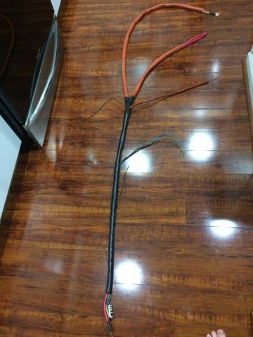
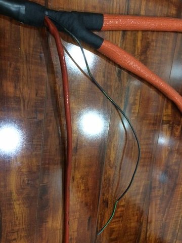
I'm almost done with my harness (pics below), the only thing left to do is terminate the ends. Where did you find the terminal that connects both the starter and alternator cables together?


#13
Rennlist Member
Thread Starter
[QUOTE=Dan87951;14845582]
Fred, where are you from?
I totally agree, most of the harnesses in these cars are way past due for replacement! I'm also thinking of taking a crack at the fuel injector harness too but would like to find a good donor harness to use as a blue print before I destroy mine. That way if I find the job too over whelming, no harm was done. It's kind of hard to gauge the difficulty level without diving in, that's what sucks! As the saying goes no guts no glory. Right?!
I'm almost done with my harness (pics below), the only thing left to do is terminate the ends. Where did you find the terminal that connects both the starter and alternator cables together?
Dan,
I am a British expatriate having worked in Oman since 1990 and now forcibly retired due to low oi prices and the subsequent collapse of the industry- that and I have had enough!.
The injection harness is not really any more complicated just measure the length of each section from the computer plugs. No idea how difficult it is to wire up the plugs of whether any special tools needed for such but apart from that not too difficult I suspect.
The crimp lugs are nothing special- they are rated by the size of the eye and the total cross sectional area of the two cables stuffed into it. Thus the stock wiring at the starter motor has a 16mm2 cable and a 10mm2 cable so the lug is a 26 by 8. The one that fastens to the alternator is a 32 by 8 and the one at the hot post is 16 by 6 lug. I had to compromise a little as the local stockist did not have a 32 x 8 so I used a 35 x 8. After crimping I fastened the lug in a vice and tugged for all I was worth to see if I could dislodge it- thankfully I could not! I also ran the cable to the ABS post as a 16mm2- theory being that if I want to install an auxiliary pusher fan in front of the a/c condenser I should be able to do so taking power from that point.
Fred, where are you from?
I totally agree, most of the harnesses in these cars are way past due for replacement! I'm also thinking of taking a crack at the fuel injector harness too but would like to find a good donor harness to use as a blue print before I destroy mine. That way if I find the job too over whelming, no harm was done. It's kind of hard to gauge the difficulty level without diving in, that's what sucks! As the saying goes no guts no glory. Right?!

I'm almost done with my harness (pics below), the only thing left to do is terminate the ends. Where did you find the terminal that connects both the starter and alternator cables together?
Dan,
I am a British expatriate having worked in Oman since 1990 and now forcibly retired due to low oi prices and the subsequent collapse of the industry- that and I have had enough!.
The injection harness is not really any more complicated just measure the length of each section from the computer plugs. No idea how difficult it is to wire up the plugs of whether any special tools needed for such but apart from that not too difficult I suspect.
The crimp lugs are nothing special- they are rated by the size of the eye and the total cross sectional area of the two cables stuffed into it. Thus the stock wiring at the starter motor has a 16mm2 cable and a 10mm2 cable so the lug is a 26 by 8. The one that fastens to the alternator is a 32 by 8 and the one at the hot post is 16 by 6 lug. I had to compromise a little as the local stockist did not have a 32 x 8 so I used a 35 x 8. After crimping I fastened the lug in a vice and tugged for all I was worth to see if I could dislodge it- thankfully I could not! I also ran the cable to the ABS post as a 16mm2- theory being that if I want to install an auxiliary pusher fan in front of the a/c condenser I should be able to do so taking power from that point.
#14
Rennlist Member
SeanR makes harnesses that are works of art if you aren't into doing your own. I am replacing my harness this spring after I heal from double carpal tunnel surgery with one of his that is sitting in my garage.
#15
Nordschleife Master
I'm trying to find a tinned copper lug that will work for this application so I can use a solder slug. I like the bond you get when using a solder slug with copper lugs.


