When you click on links to various merchants on this site and make a purchase, this can result in this site earning a commission. Affiliate programs and affiliations include, but are not limited to, the eBay Partner Network.
yes. What do we later 32v owners use? Inquiring minds would like to know
The plastic filler necks have the louvered part (the metal piece with the O-ring around it, which is NLA, mentioned above) built into the filler neck.
All one needs is a new O-ring that fits into the groove in the filler neck. Apply a thin layer of Drei Bond between the baffle and the block. Install baffle. Apply thin layer of Drei Bond to both sides of the new "O-ring. Install and tighten filler neck. You should see the Drei Bond squeeze out between all the pieces. Use your finger to smooth out the excess Drei Bond, leaving it present to act as an extra layer of leak protection.
Works great. This area will never leak again. Drei Bond is magical stuff.
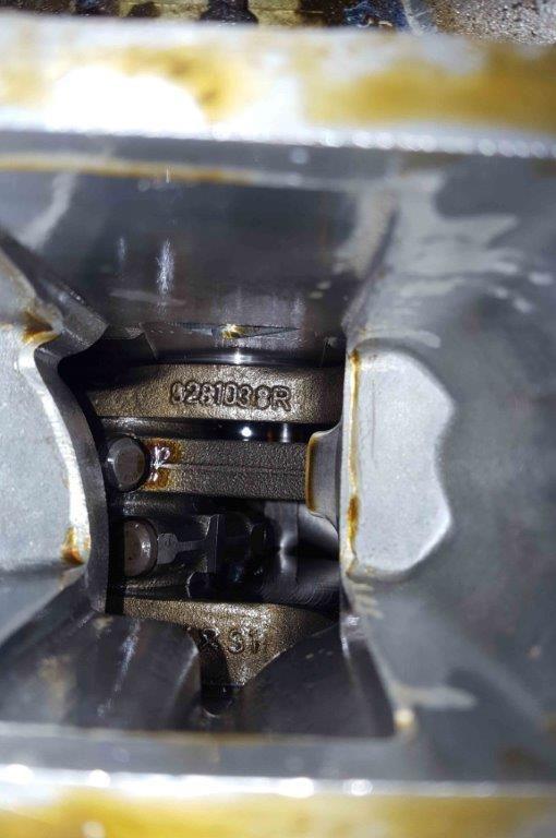
Here's looking down the oil filler passage in the engine block to the crank. Big chimney that let oil splash upward. Or as Greg said "there is a virtual rainstorm of oil being thrown up at the filler neck".
Here's looking down the oil filler passage in the engine block to the crank. Big chimney that let oil splash upward. Or as Greg said "there is a virtual rainstorm of oil being thrown up at the filler neck".
That's a good picture. There are a couple of things that are going to happen there. First, you'll get three oil sprays directly from the rod bearings. The center between the two rods and both outsides. In a perfect vacuum crankcase, those would form spiral discs. In addition, though, we have crankcase pumping pulses that push crankcase gas from bay to bay. Those pumping pulses in general convert the spiral discs into a helix shape. Then this helix hits any solid boundary of the crankcase and reflects as smaller droplets with a little bit of shatter. The existence of a breathing hole and the rod bearing spray all in this single cavity makes the baffle design problem an interesting one. One first has to block all direct spray and reflected spray as well as one can. Then one needs to decelerate the crankcase gas inside the baffle as much as possible to allow for oil separation.
Adding the external forces on the engine in different operating modes makes the problem even more interesting. For example, would you want to pick up the crankcase gas from the oil filler neck under high-rpm throttle closed deceleration? I wouldn't.
I think the solution to oil ejection from breathers in a normally aspirated engine is to
(1) Put a baffle inside the chimney. I know John's version without the scrubber works, I'm sure your works, too. If one wanted to improve either design, one idea I'd consider is putting the inlet port in the baffle right above the counterweight, but right now I'm not looking to fix what's working.
(2) Vent the oil filler neck from the top. For mild engines, the GTS breather neck port is probably enough, but for high powered engines one probably wants a large port or ports. The port requirements can in my opinion be sized for a specific engine using a blow-by meter.
(3) Include a properly sized air-oil separator. I personally think the BMW cyclonic separators are the best option for 928 engine bay (and especially in cold climates) but if one can fit properly sized ProVent may work, too. I couldn't so I switched away form the ProVent.
(4) Drain the separator to pan with a check valve in line. That check valve is a precaution for some pressure events pushing oil up in some circumstances.
(5) Run the separator gas outlet to the Y-piece in the MAF rubber elbow.
(6) For cars in cold climates, include the pressure relief valve and second gas hose from the oil filler neck to the Y-piece in the MAF elbow. Stock S4 parts work. This path should only vent if the main gas path has condensation water and freezes or has some other blockage. It's the option of last resort, a final final fail safe only.
(7) Interconnect the two front valve cover ports with a hose. Port those to flow as much as you can and use hose that is not a restriction. This achieves both pressure equalization when there's trouble and also sets up an air circulation scheme that helps prevent sludge. Similar to the later GTS versions.
(8) Block the small 2mm orifice port on the oil filler neck.
(9) Connect the complex three way hose that goes to the tank vent valves etc. and the intake manifold plenum to the rear passenger side valve cover port. Include a 2mm restrictor. The easiest way to do this is to get an additional hose, run it from the rear passenger valve cover port to a restrictor that also serves as a hose connector and connect that to the hose that in stock setting goes to the small 2mm port in the oil filler neck on the driver side.
(10) Drill a small hole in the top of the shroud tube in the rear passenger side valve cover port. I don't think this is strictly necessary given this particular setup that only vents out of this port with the throttle closed, but it'll give one some peace of mind.
I think this doesn't come to close to solving all the 928 oiling problems, but it in my experience will dramatically cut the oil consumption in engines where the oil consumption was caused by the stock breather system ejecting oil into the intake manifold.
I have a forced induction engine, what about my set up?
In my turbo car, I have turbo oil sumps and an auxiliary pump evacuating them. This makes my problem both harder and easier.
For a belt driven supercharger placed above the oil level and thus passively draining to the oil pan, I think that the above listed 10 steps improving the normally aspirated breather would work, but with two modifications. First, the Y piece hoses would need to be connected to the air filter upstream of the compressor inlet. Second, the line from the complex three-end hose to the intake manifold plenum needs a check valve in it to prevent manifold pressure from pressurizing the crankcase.
One word of warning is that if the system has a blow-thru MAF, then you want to make sure the air-oil separator is really working because, even with its burn-off cycle, the MAF hot wire doesn�t like to see too much oil... this is the reason why factory supercharged cars use draw thru MAFs or speed-density systems.
I think the solution to oil ejection from breathers in a normally aspirated engine is to
(1) Put a baffle inside the chimney. I know John's version without the scrubber works, I'm sure your works, too. If one wanted to improve either design, one idea I'd consider is putting the inlet port in the baffle right above the counterweight, but right now I'm not looking to fix what's working.
(2) Vent the oil filler neck from the top. For mild engines, the GTS breather neck port is probably enough, but for high powered engines one probably wants a large port or ports. The port requirements can in my opinion be sized for a specific engine using a blow-by meter.
(3) Include a properly sized air-oil separator. I personally think the BMW cyclonic separators are the best option for 928 engine bay (and especially in cold climates) but if one can fit properly sized ProVent may work, too. I couldn't so I switched away form the ProVent.
(4) Drain the separator to pan with a check valve in line. That check valve is a precaution for some pressure events pushing oil up in some circumstances.
(5) Run the separator gas outlet to the Y-piece in the MAF rubber elbow.
(6) For cars in cold climates, include the pressure relief valve and second gas hose from the oil filler neck to the Y-piece in the MAF elbow. Stock S4 parts work. This path should only vent if the main gas path has condensation water and freezes or has some other blockage. It's the option of last resort, a final final fail safe only.
(7) Interconnect the two front valve cover ports with a hose. Port those to flow as much as you can and use hose that is not a restriction. This achieves both pressure equalization when there's trouble and also sets up an air circulation scheme that helps prevent sludge. Similar to the later GTS versions.
(8) Block the small 2mm orifice port on the oil filler neck.
(9) Connect the complex three way hose that goes to the tank vent valves etc. and the intake manifold plenum to the rear passenger side valve cover port. Include a 2mm restrictor. The easiest way to do this is to get an additional hose, run it from the rear passenger valve cover port to a restrictor that also serves as a hose connector and connect that to the hose that in stock setting goes to the small 2mm port in the oil filler neck on the driver side.
(10) Drill a small hole in the top of the shroud tube in the rear passenger side valve cover port. I don't think this is strictly necessary given this particular setup that only vents out of this port with the throttle closed, but it'll give one some peace of mind.
I think this doesn't come to close to solving all the 928 oiling problems, but it in my experience will dramatically cut the oil consumption in engines where the oil consumption was caused by the stock breather system ejecting oil into the intake manifold.
Interested in your thoughts on this.
Different cars need different systems/ideas, totally dependent upon how they are driven.
Regardless of which engine family, the condition of the engine, or how it is driven, they all will benefit from a properly engineered oil baffle under the filer neck.
There are very good baffles, medium useful baffles, and baffles that have very limited usefulness. Pure common sense eliminates the baffles with limited usefulness. Just look at what you are about to use or buy and think about a rainstorm of oil hitting that baffle. If the part of the baffle that hangs down into the block has open sides, the oil/air is going to blow right around the sides of the metal hanging down and have a direct path to the opening/secondary baffle at the filler neck, going right through the open sides.These baffles are largely home made, "early" attempts at making something to help, or baffles from someone who doesn't have a clue what is happening inside the engine.
We've just made a post in another thread (https://rennlist.com/forums/928-foru...mparisons.html) showing how how my baffle works. There was a tremendous amount of engineering and testing involved in the design of this baffle.
Cars that have good rings, valves, and guides and are Sunday cruisers or daily driven cars which seldom get run up in the higher rpms can use just an additional baffle under the filler neck.
Vehicles that are run harder generally need more that just a baffle. I've got several different levels of pieces, completely dependent upon the model year, and how the car is driven. Most all of my various "systems" abandon the filler neck return to the intake. At high rpms for extended periods of time, there is no possible way to keep the filler neck area from becoming completely packed with oil and it becomes impossible to separate the air from the oil, in that constrained area.


 10-17-2017, 10:40 PM