When you click on links to various merchants on this site and make a purchase, this can result in this site earning a commission. Affiliate programs and affiliations include, but are not limited to, the eBay Partner Network.
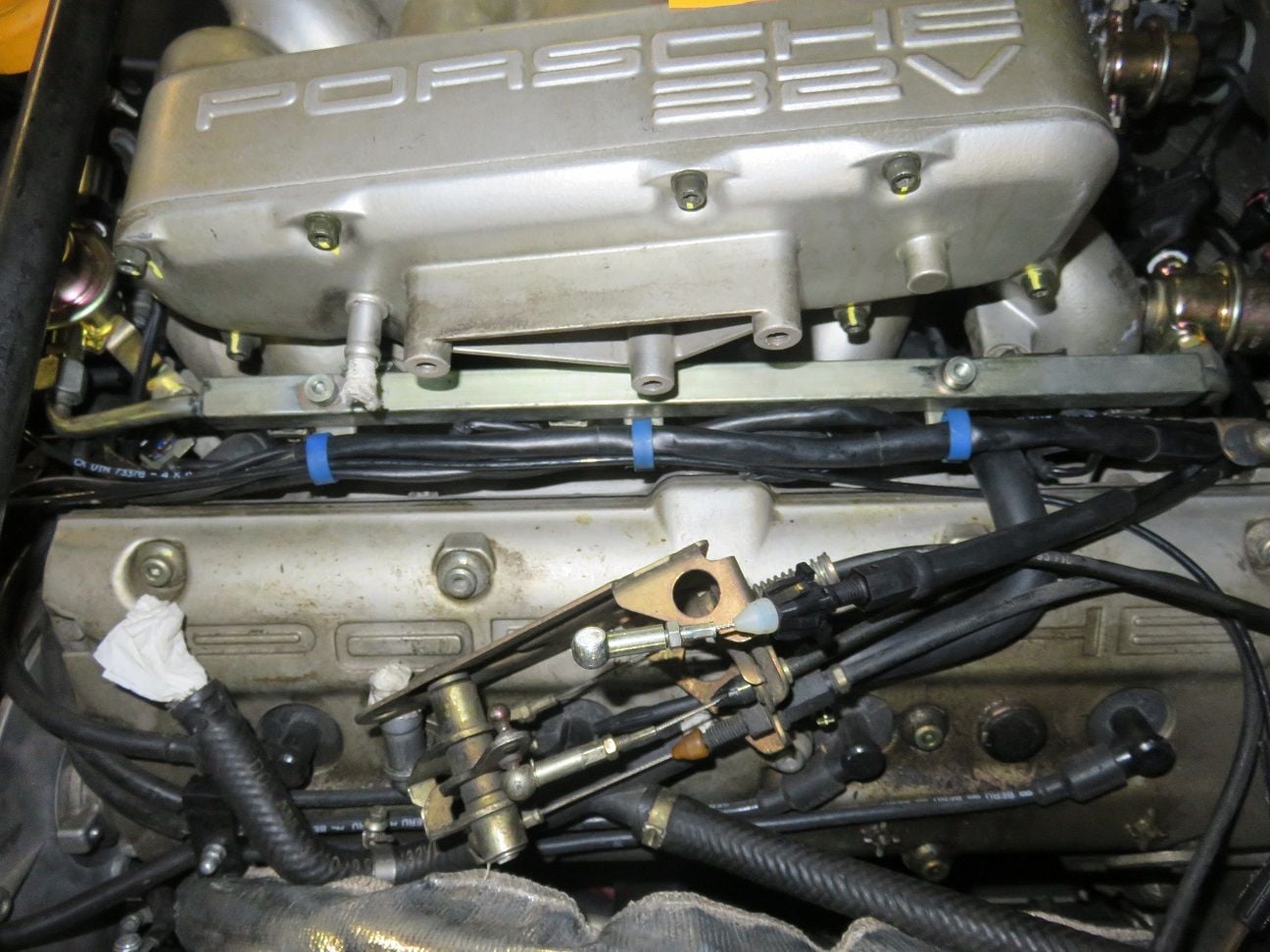
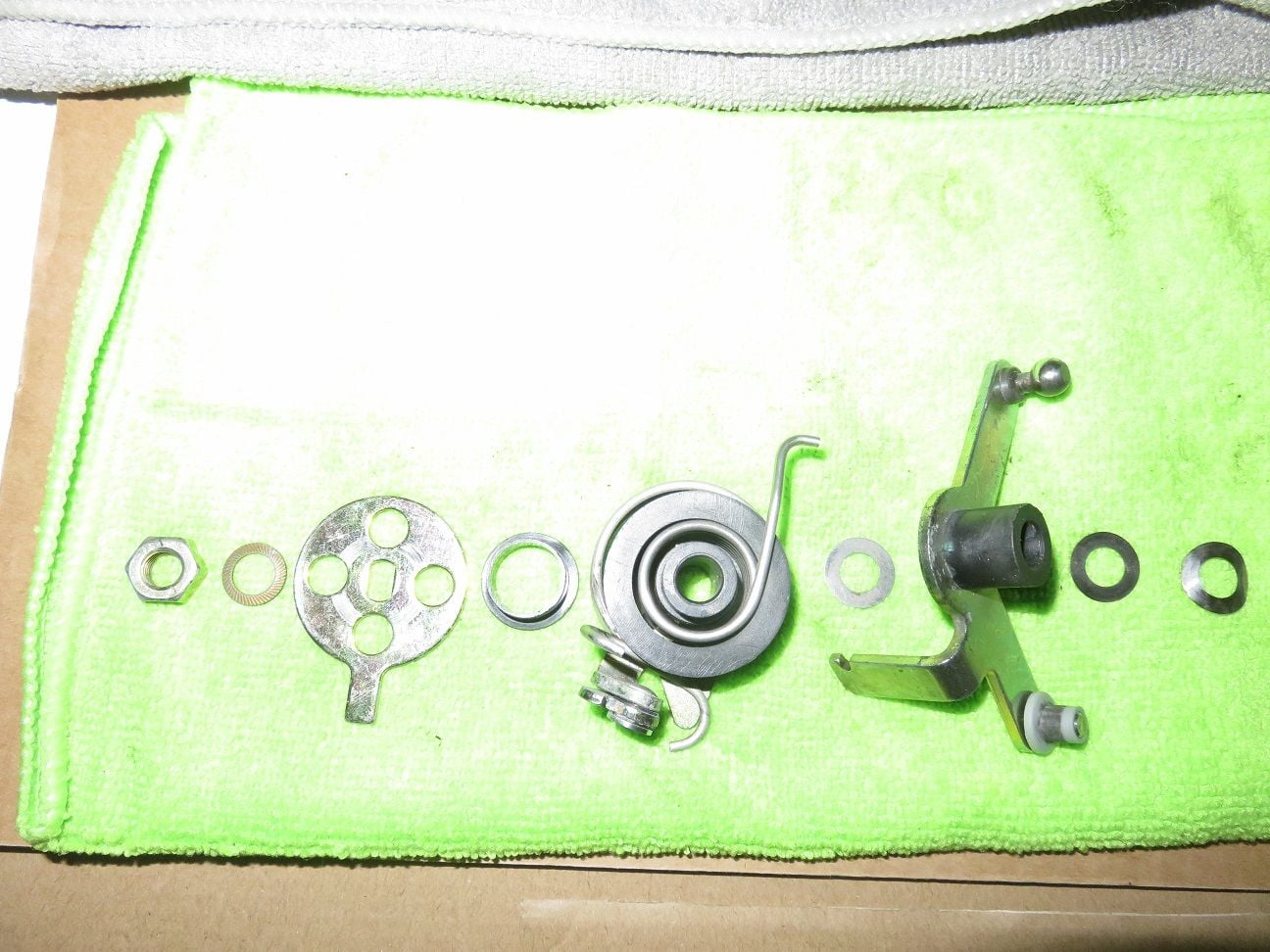
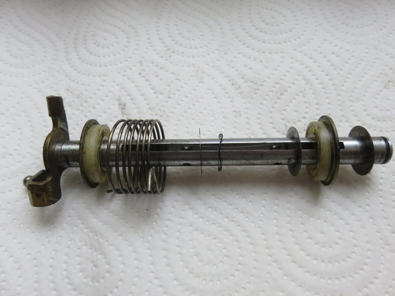
My throttle cable lever arm disassembly order (from left to right):
Flappy spindle, as it came out:
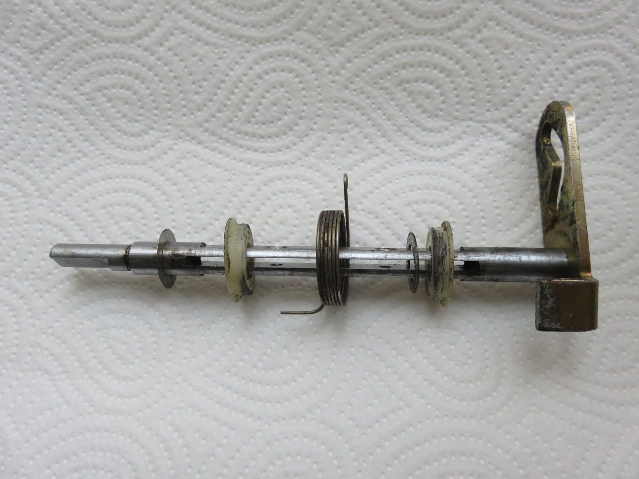
Throttle body spindle, as it came out:
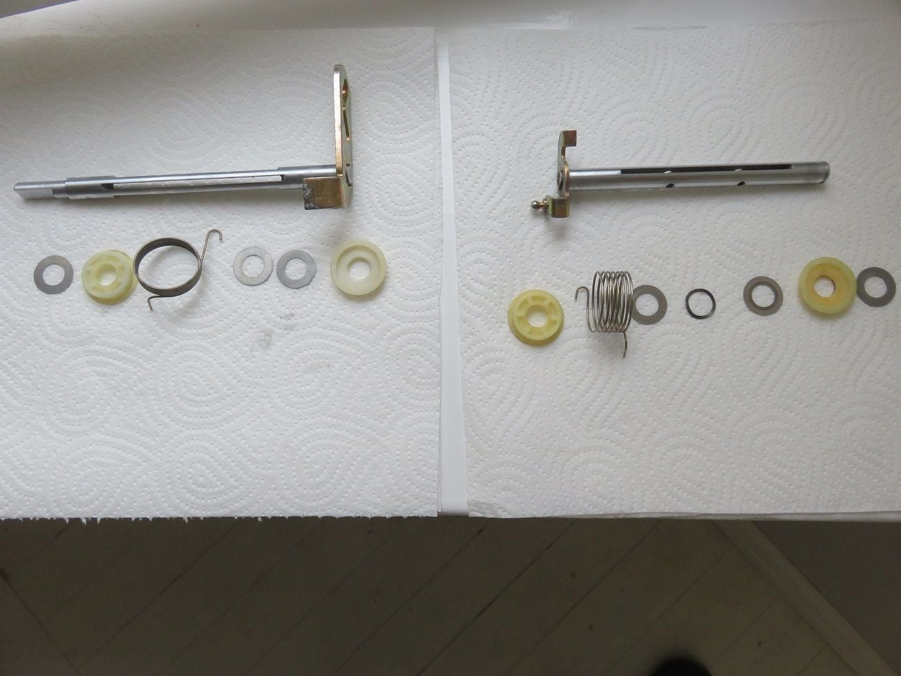
Both cleaned up (it always amazes me, what a good job simple break cleaner does):
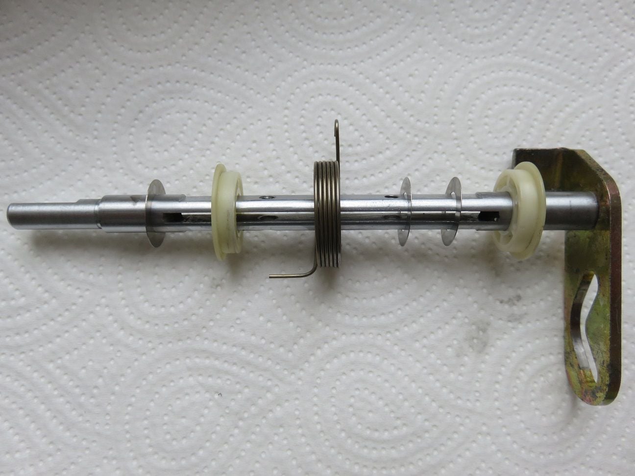
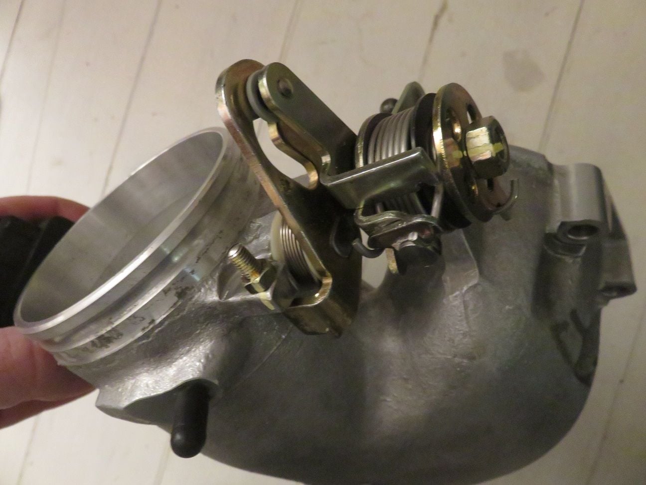
Re-assembled (and used just a little bit of silicone lube on the shafts):
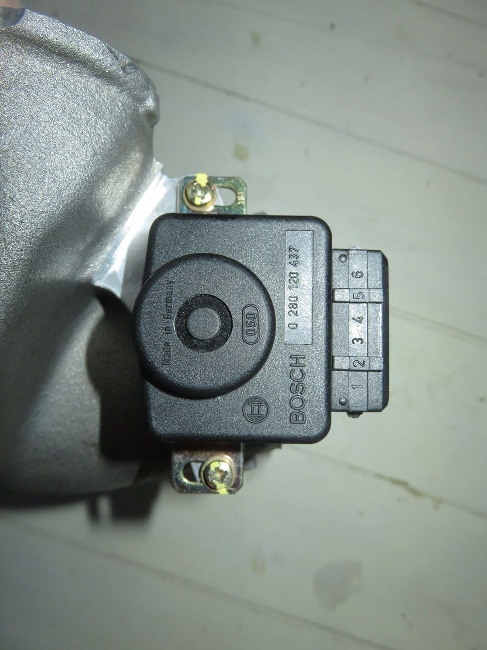
New TPS re-installed and calibrated for the 1% open IDLE "click":
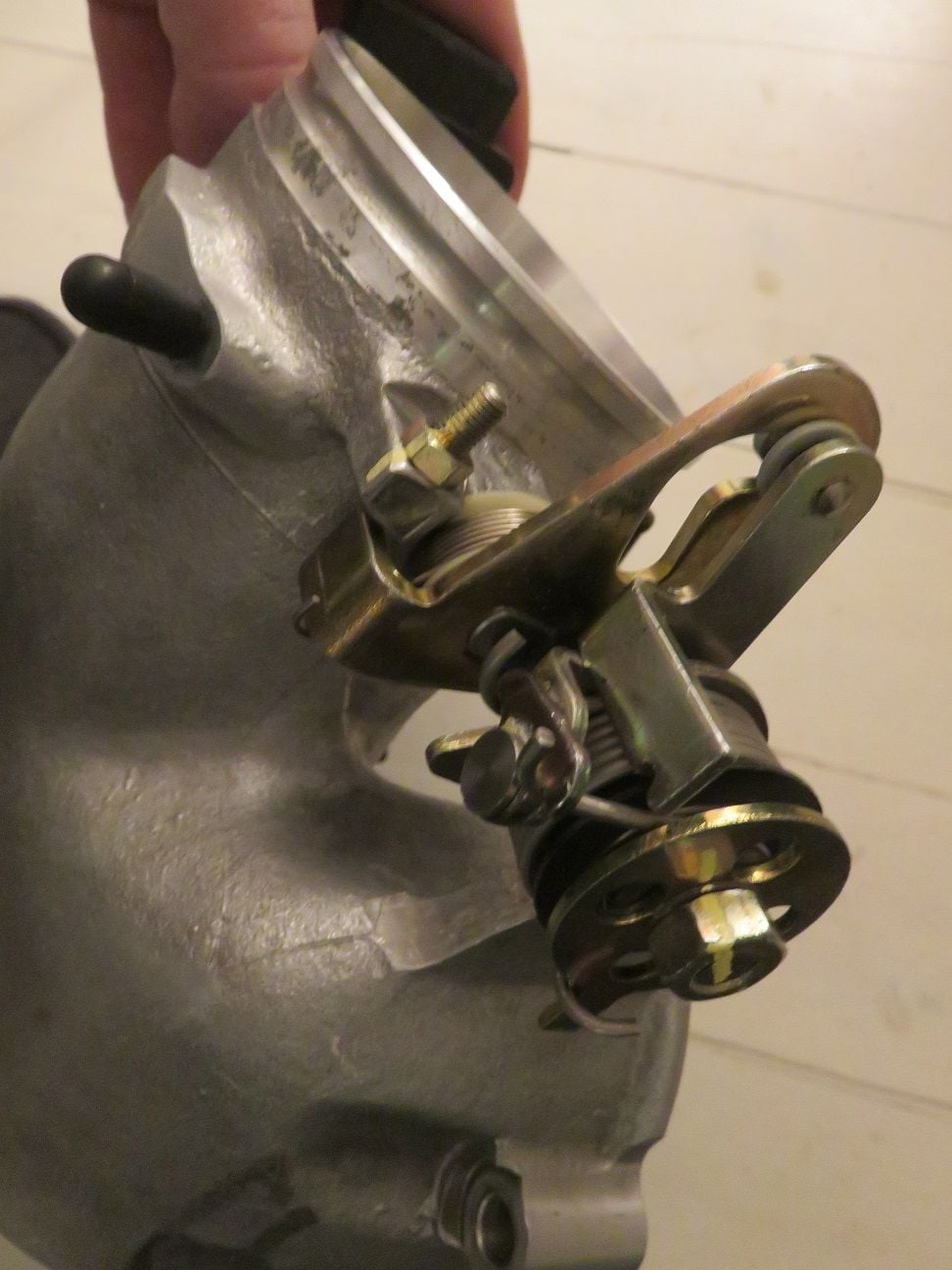
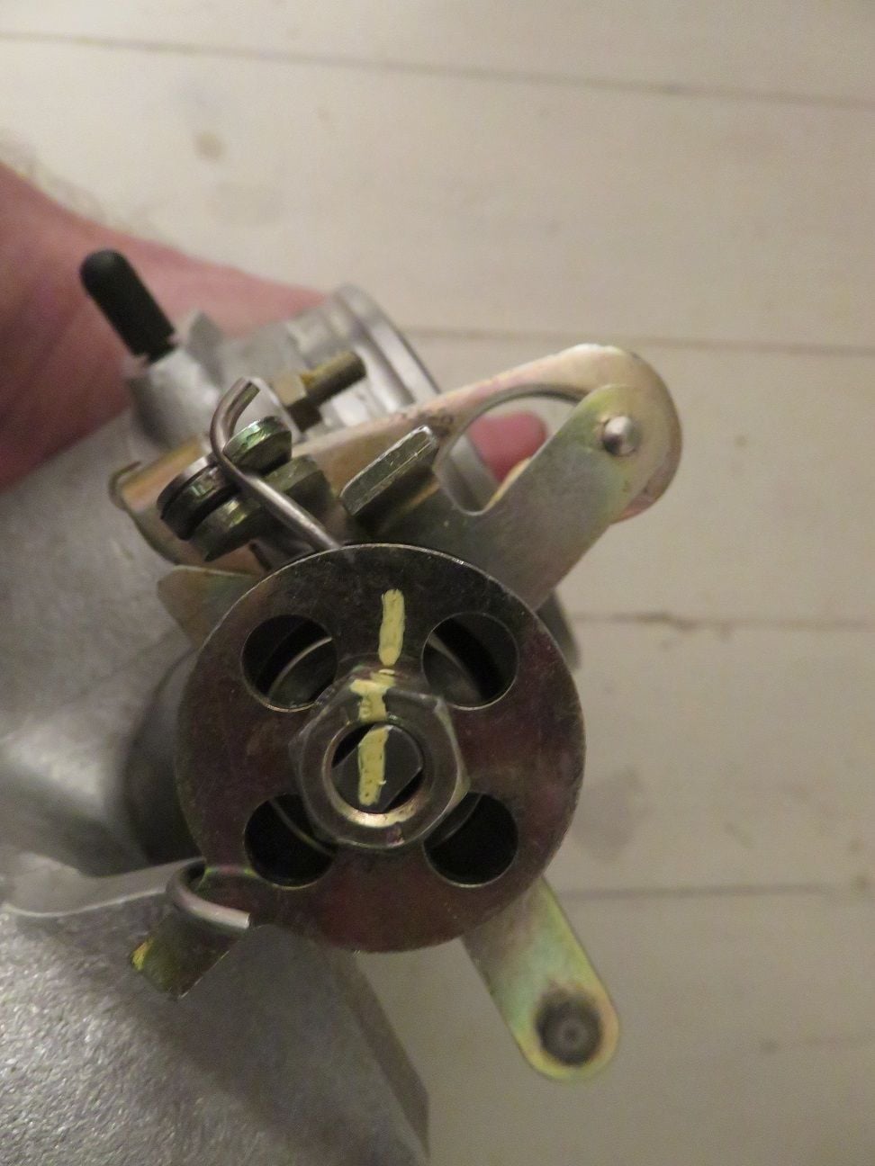
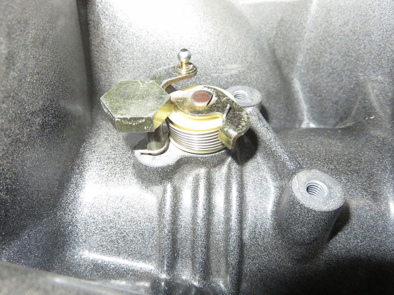
I had a bit of a "fight" with getting the springs back onto that latch, the following three photo's should help with showing where what goes back:
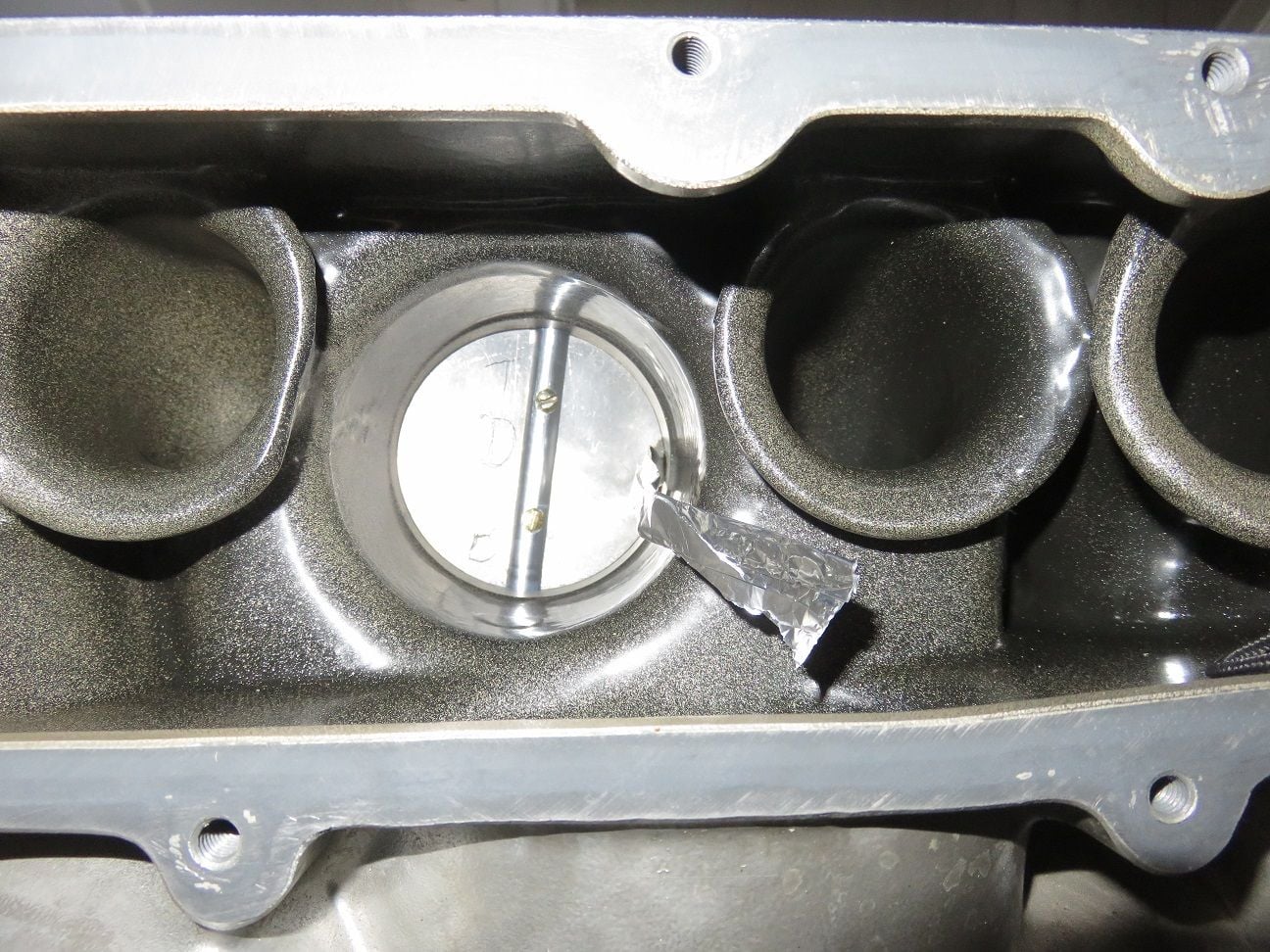
I used thread sealant om the flappy screws before putting them back in, and I used a strip of a few times folded aluminium foil so to hold the flappy just open and to be able to put the stop screw back in the correct position (and I also put thread sealant on it):
Showing the stop screw back on/in place:
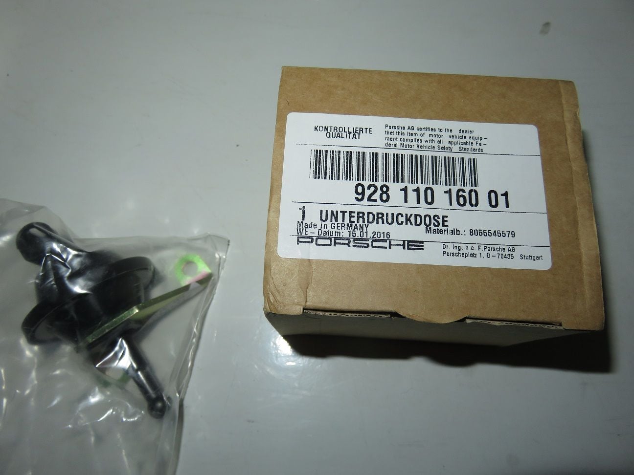
Renewing the flappy vacuum pod (the old one was working fine, but I do not want to have to go back in here for many years to come):
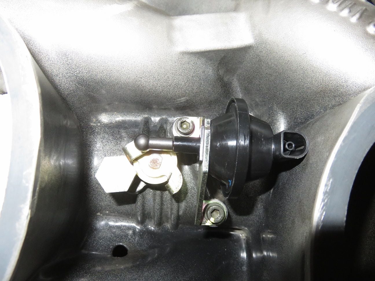
And put into place (and screws torqued to spec):
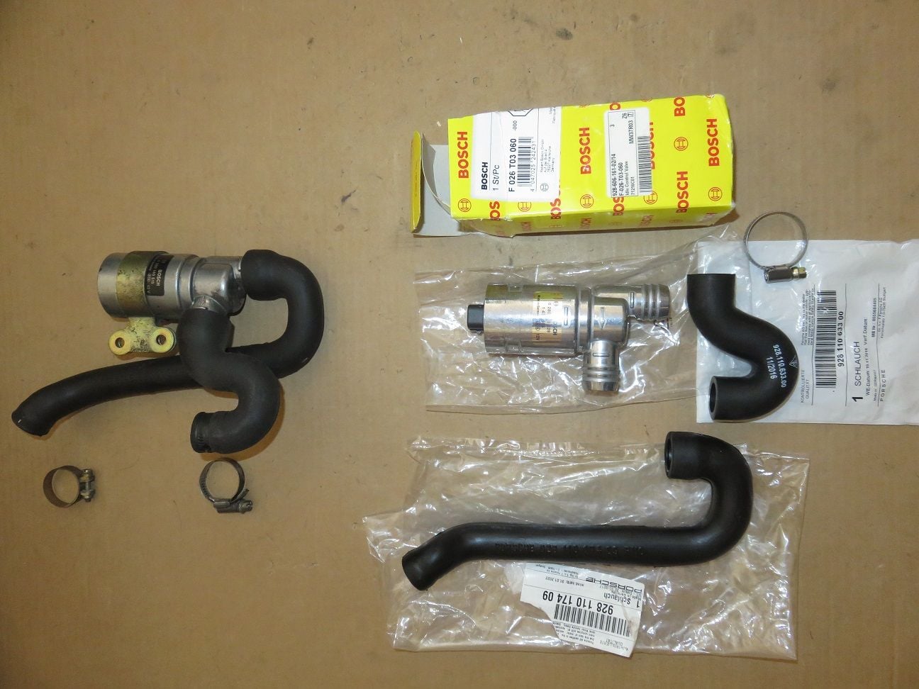
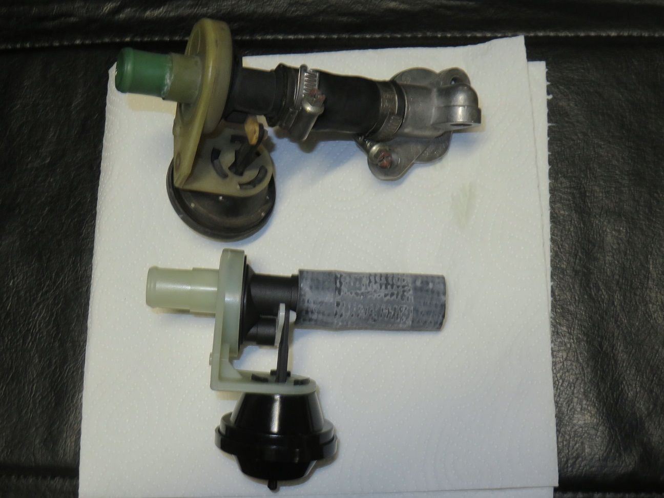
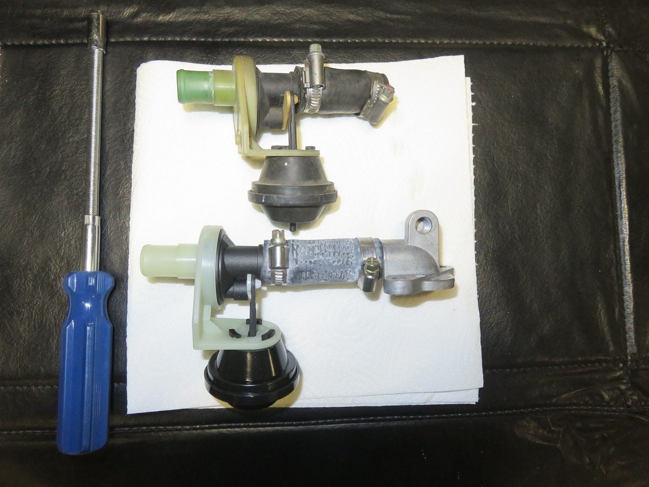
Old and new ISV parts:
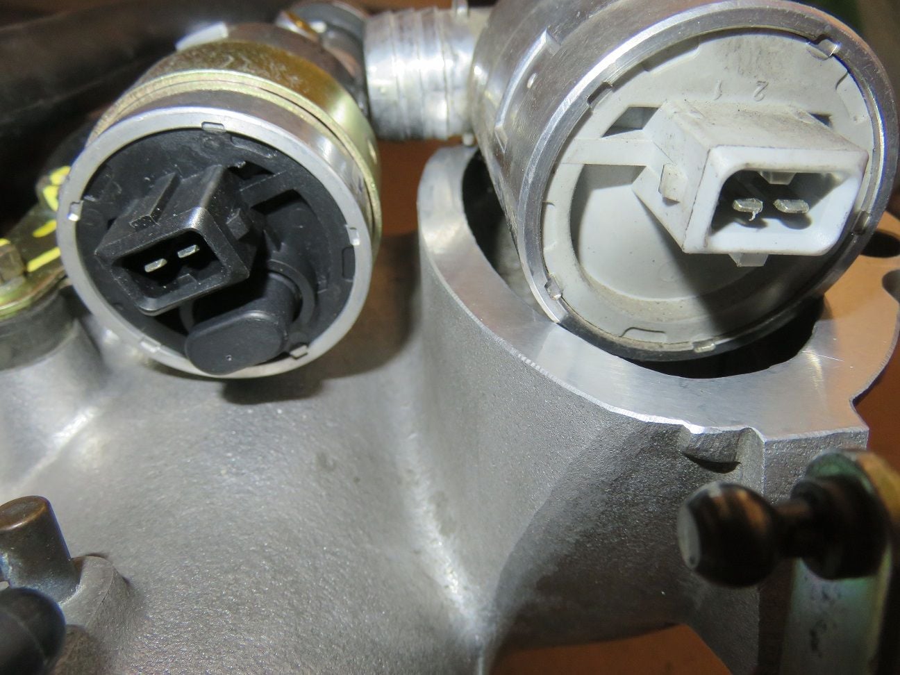
New and old ISV are clocked 180 degree with regards to the connector. Not a problem, just good to know for when putting the connector back on:
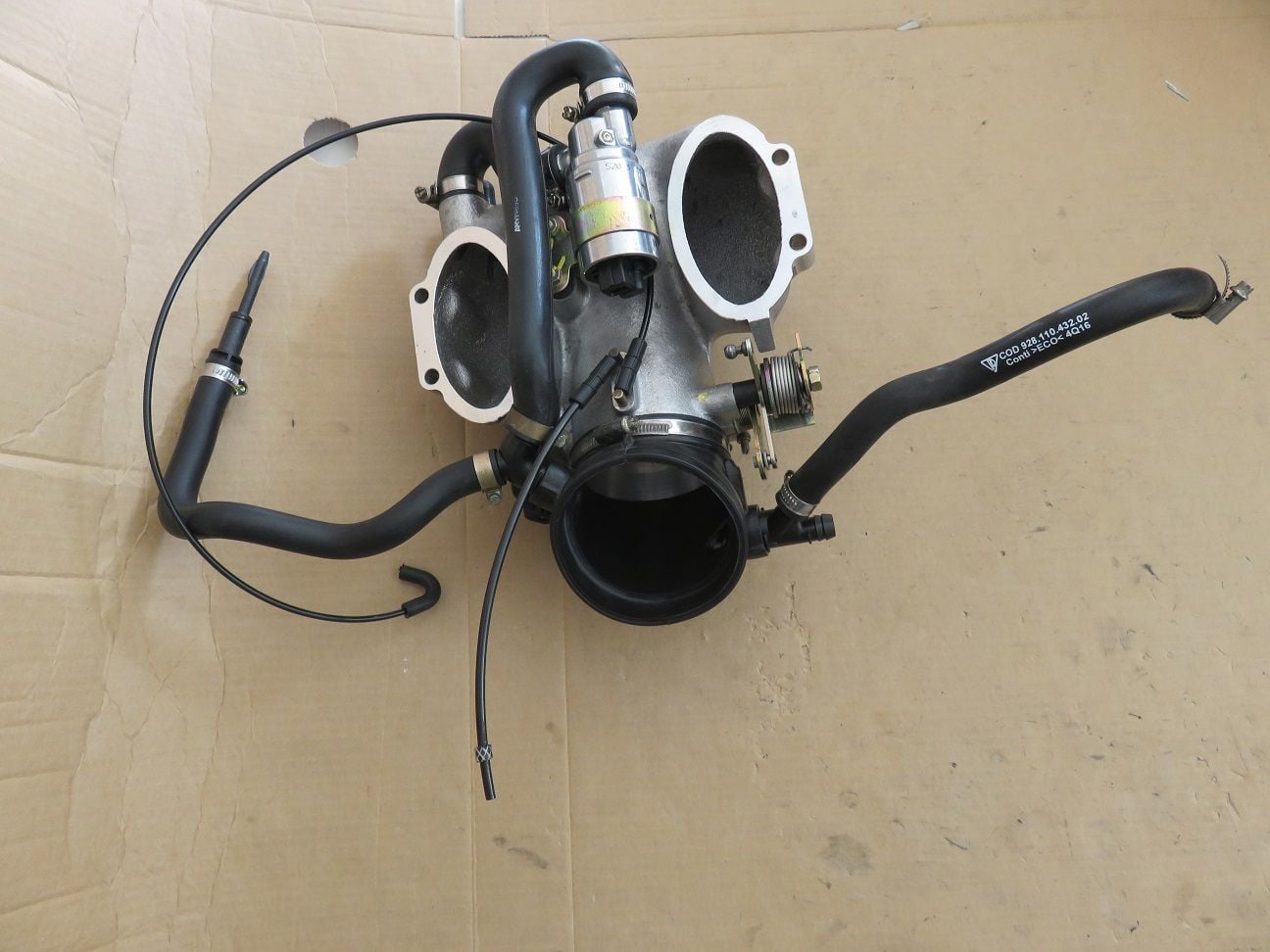
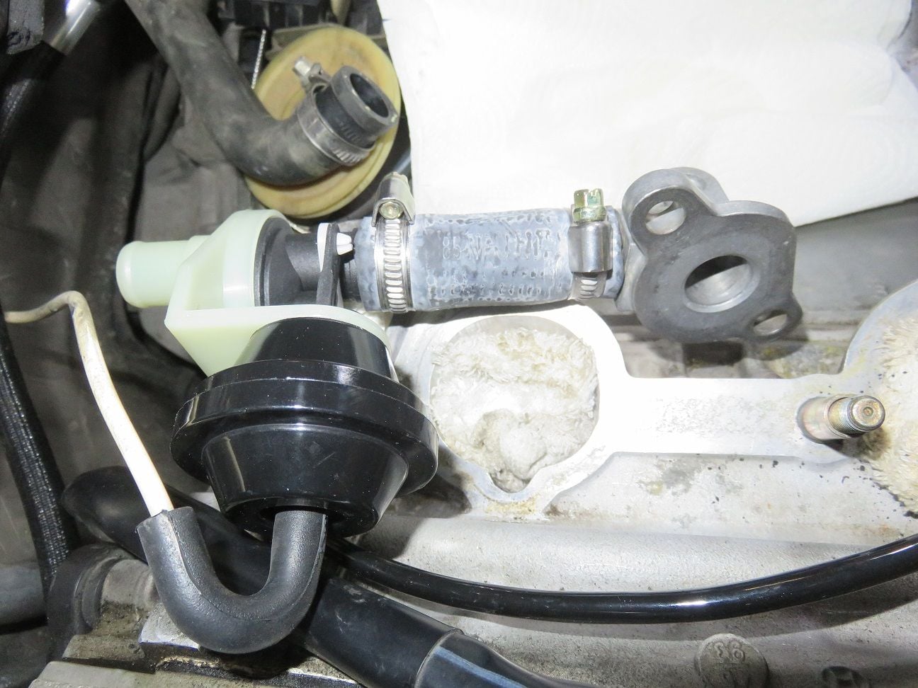
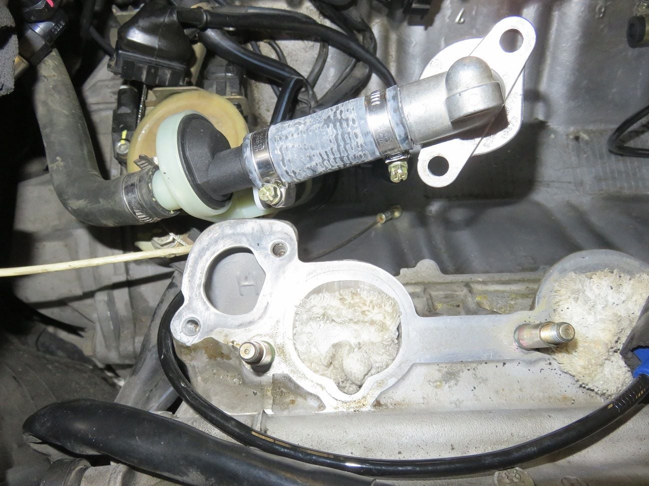
All new items connected up to the trottle body:
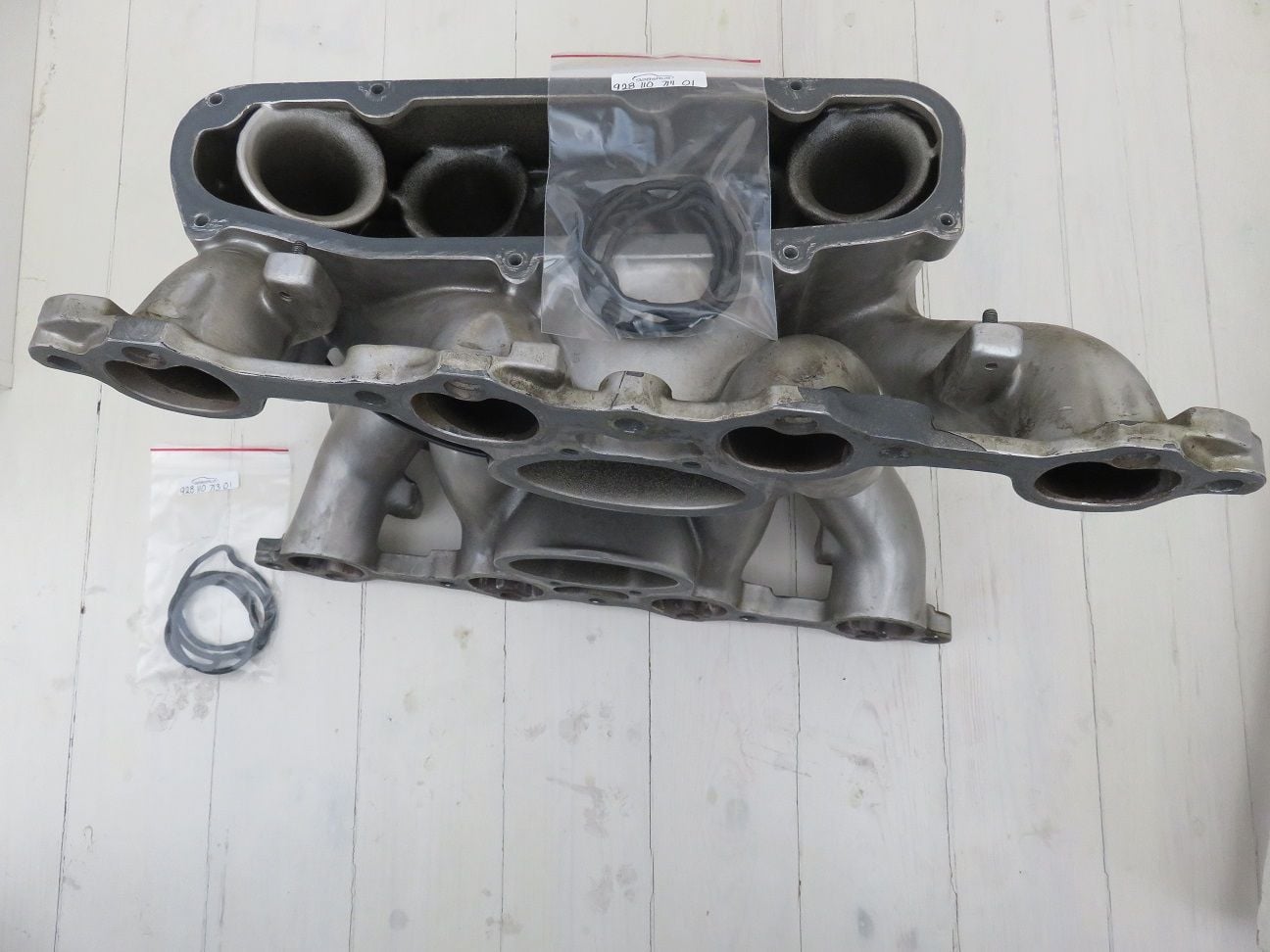
New seals for the side plenum plates, after first having cleaned the side plenum plates and having used a razor blade (followed by brake cleaner and lots of wiping) for making the sides and the bottom as smooth as possible:
Side plenum with new seals in place, just before re-installation:
And after having torqued the side plenums back on:
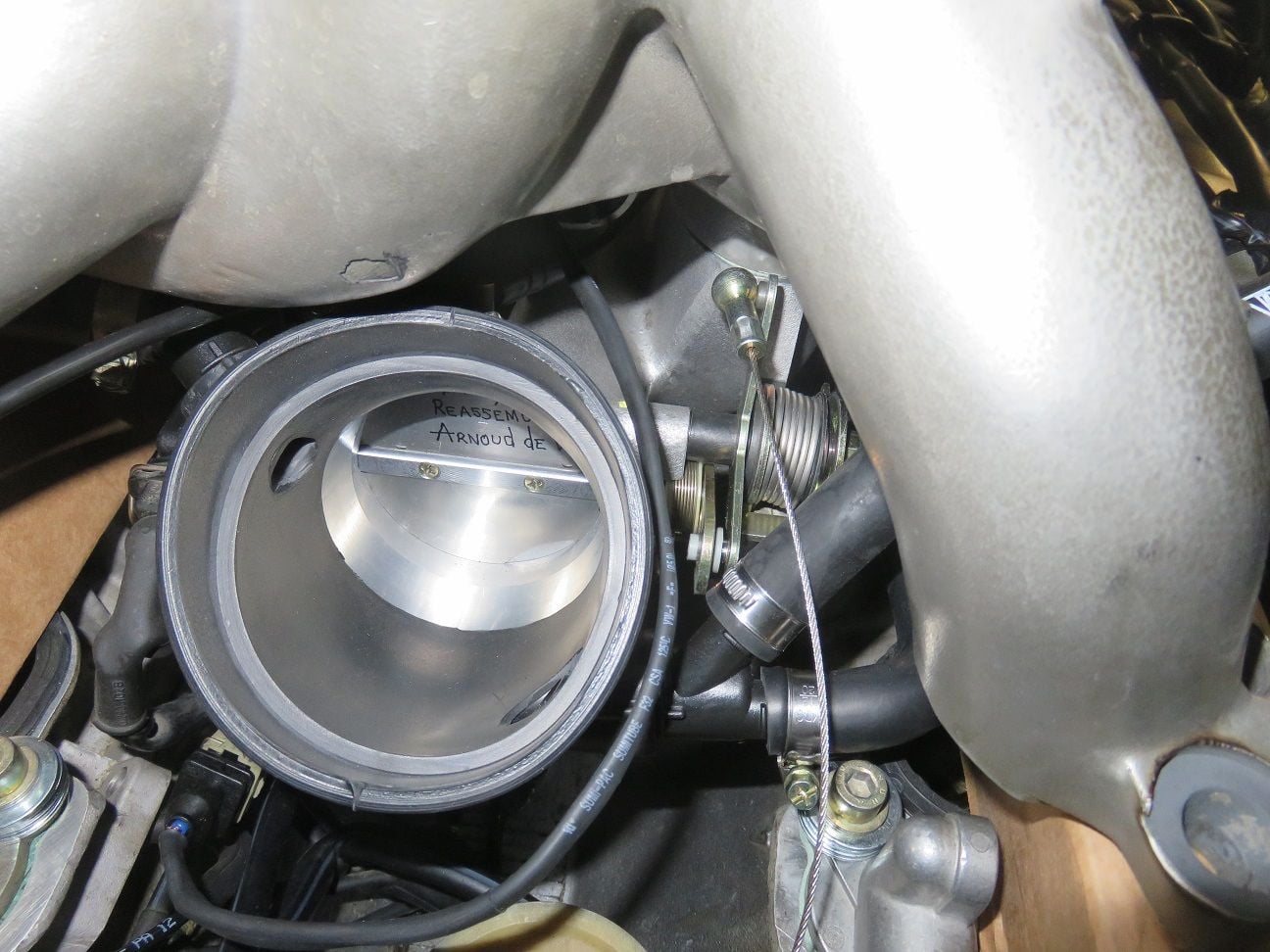
Trottle Body back on, and torqued to spec:
Last edited by Arnoud; 07-23-2018 at 06:15 PM.
Reason: Added one more picture (at the start), for completion.
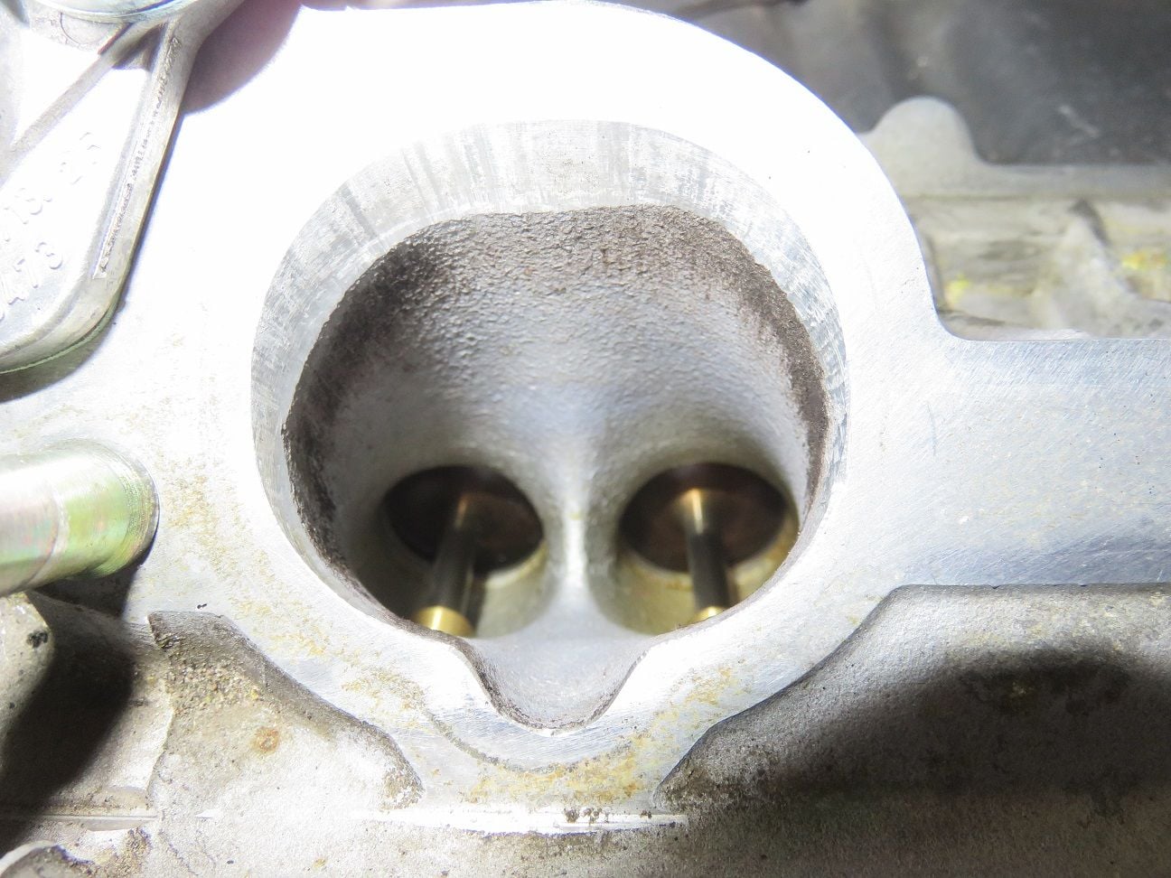
before you fit the intake to the engine I would suggest to test fit the injectors in each hole ,
NOTE if any of the PC has come off with the old injector O rings,
then the chances are good you will have an intake leak at the injector seals.
NOTE the best way to prevent this is to have the intake powder coated including the injector holes
Once I reach that stage I will test fit it and report back on it. And: thank you very much, Stan, for always giving straight to the point advice to DIY'ers like me, this is what makes this 928 Rennlist community so great!
What happened next with my intake refresh: more pictures and text to come, including also one big "oh...crap" type of moment...
Watching this as I have the same issue with an 86. Starts and idles well but stumbles at 1800 - 2000 rpm but smooths out over about 2500. Removed intake, repaired all wiring, replaced all hoses I didn't replace 4 years ago which were in good nick as I haven't driven it too much.
Subscribed
hey bogdann...I had similar problem with my S3 and key was opening the idle bypass screw (do it by 1/8th turn) ....to open the screw (allow more air in...turn it counterclockwise. Again..no more than 1/8 turn each time..you want to open the screw as little as possible in order to address the issue...
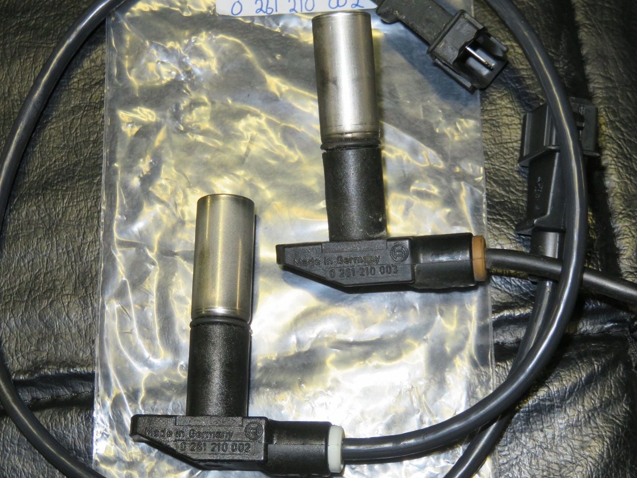
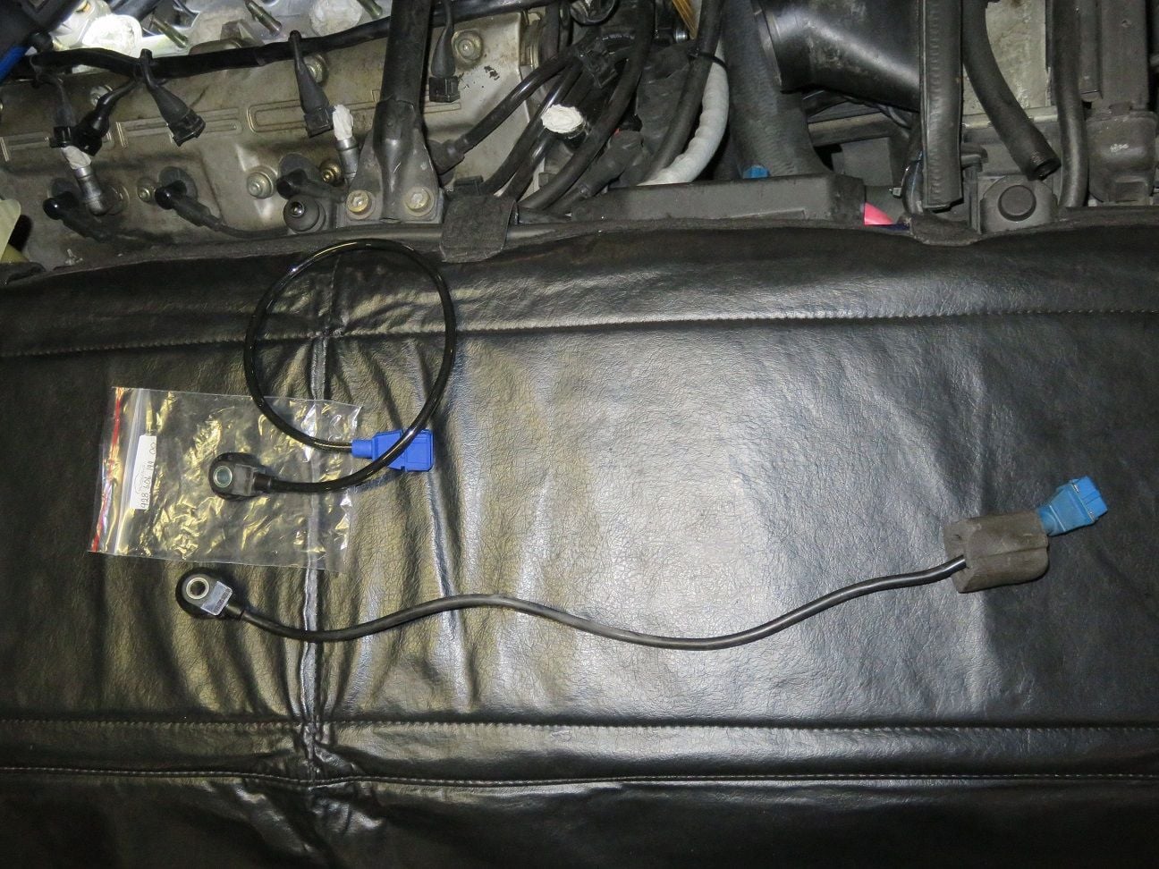
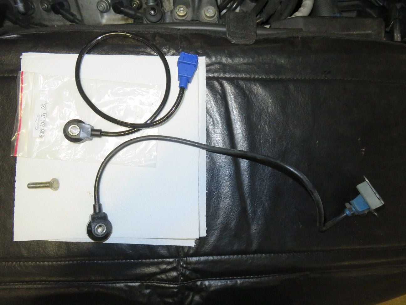
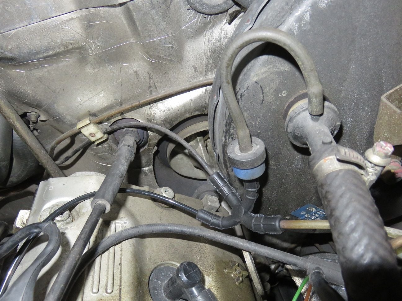
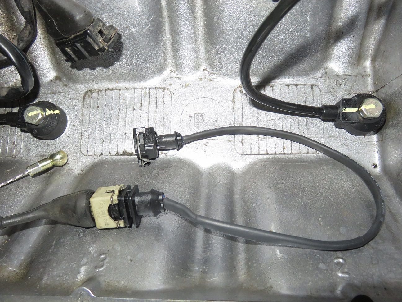
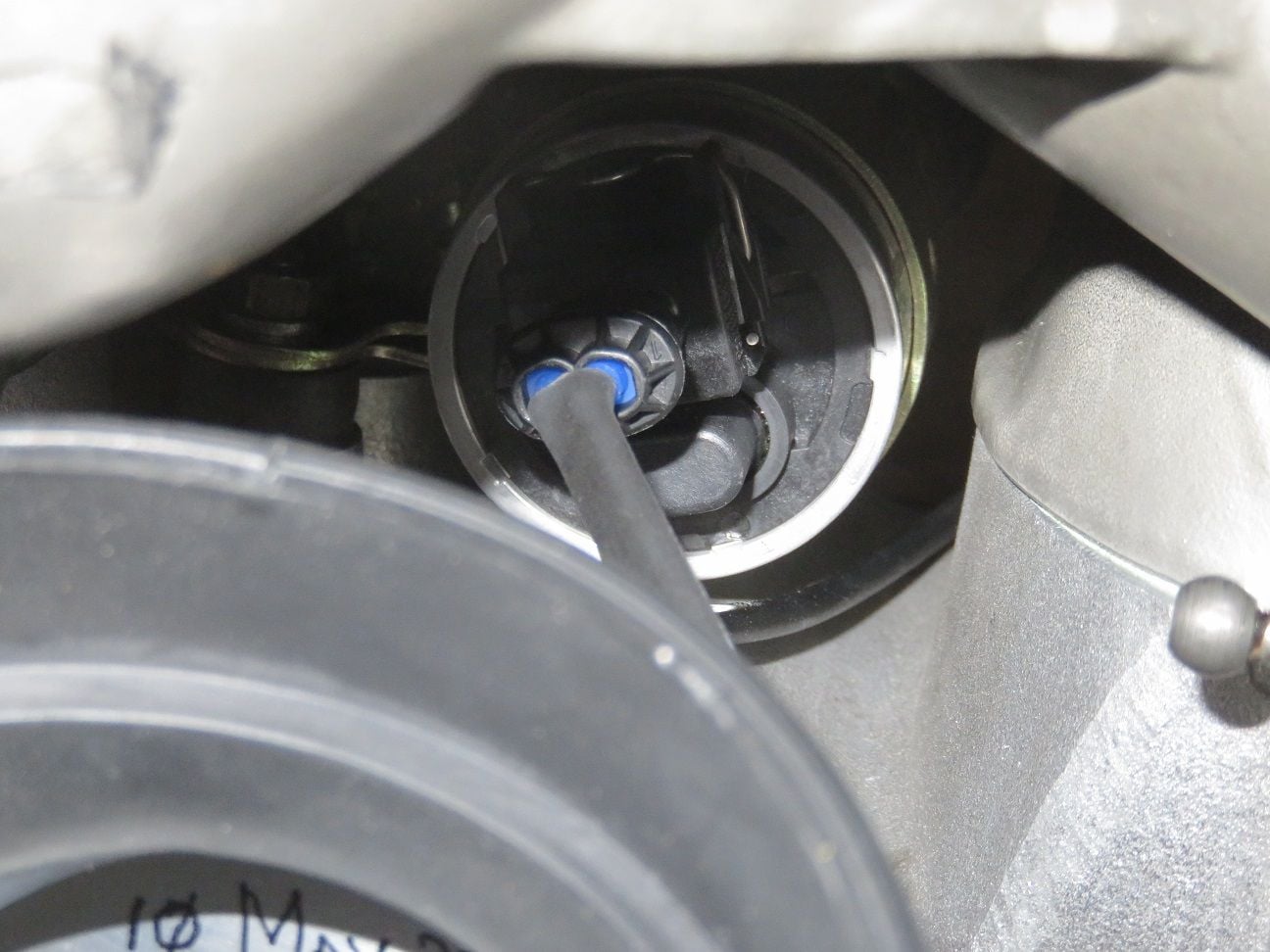
As you can see: the CPS connector plastic edge piece was broken, even thought the electrical connections were still fine. Anyway, as was always part of this intake refresh: time to replace the CPS.
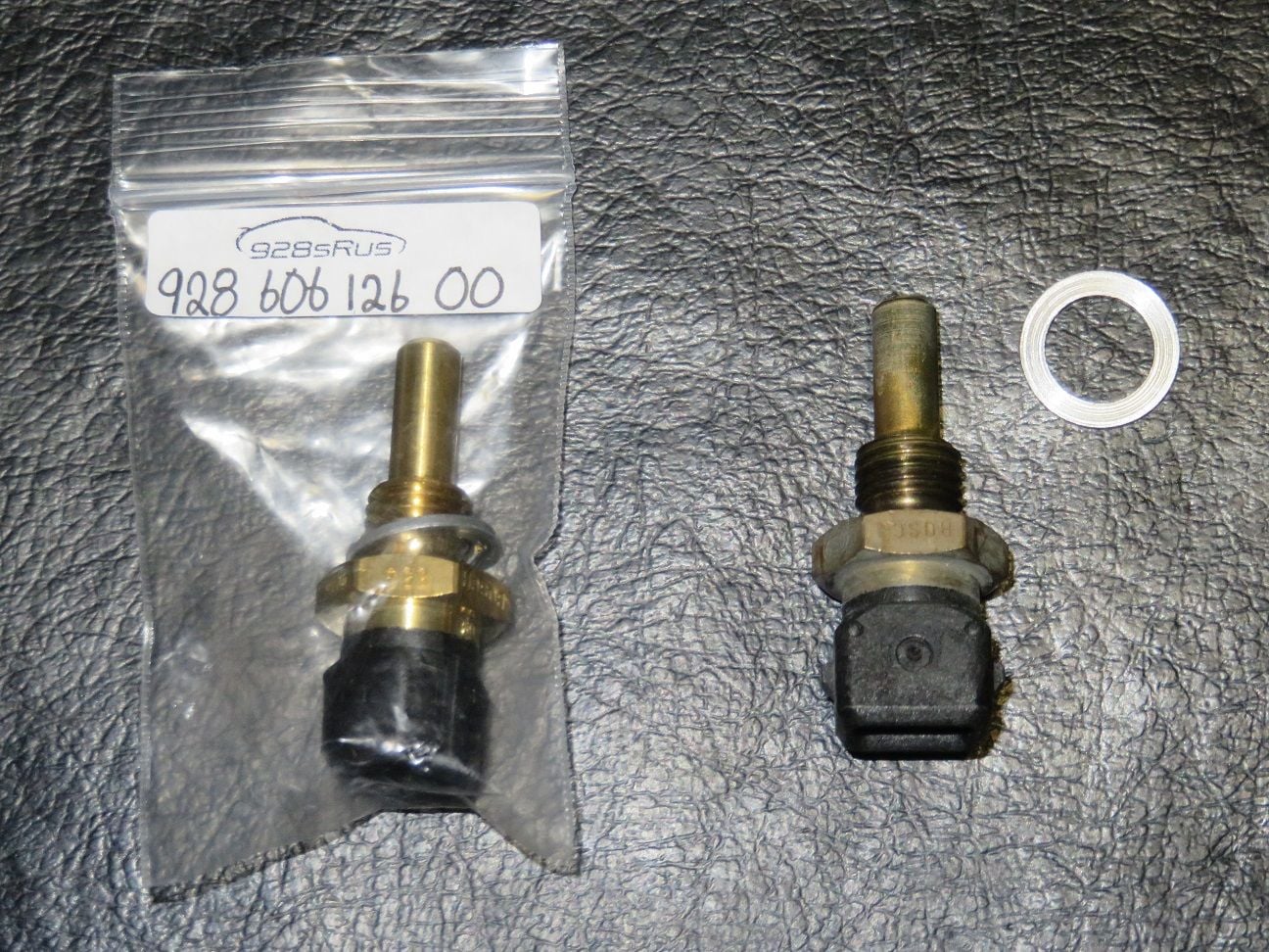
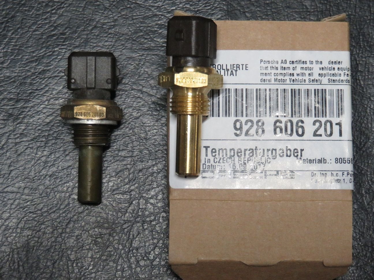
New - on the left side - and old - on the right side - CPS. Interesting that the serial number of the new CPS is ...002, while the old one is ...003. The only physical difference I noted is that the new one (with the ...002 serial number) cable is longer: 61cm oppose to 38cm of the old one.
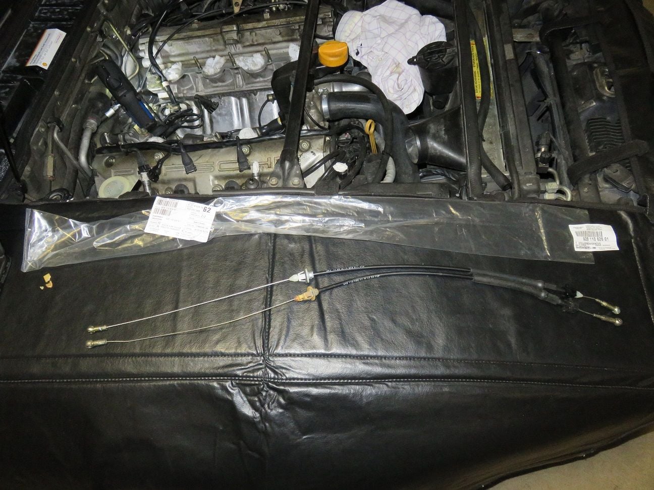
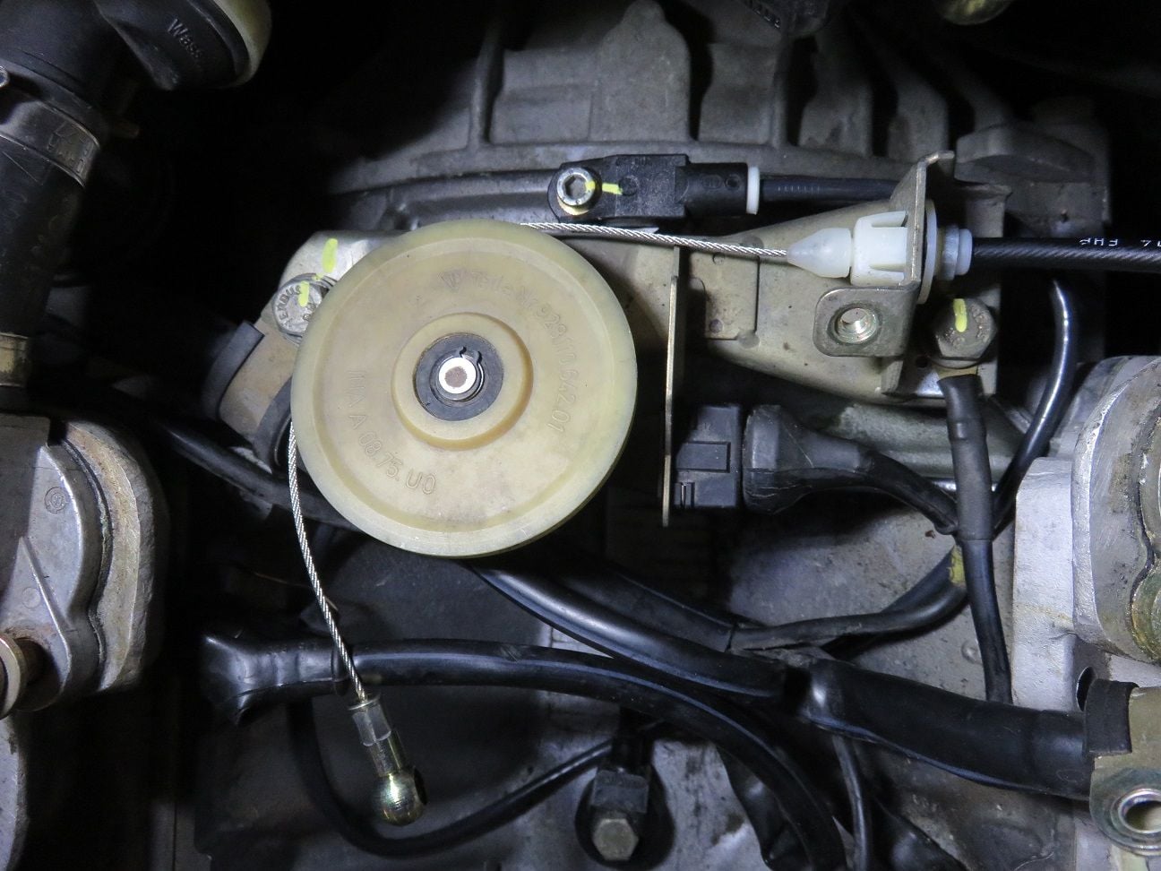
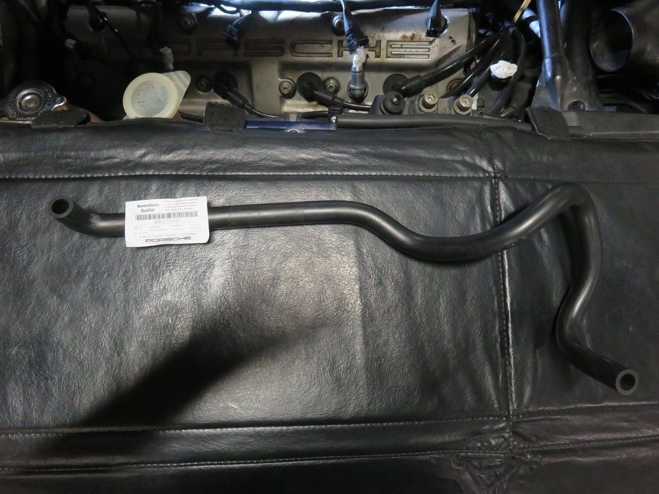
Also putting in a new Bowden cable, as the old one had broken plastic pieces.
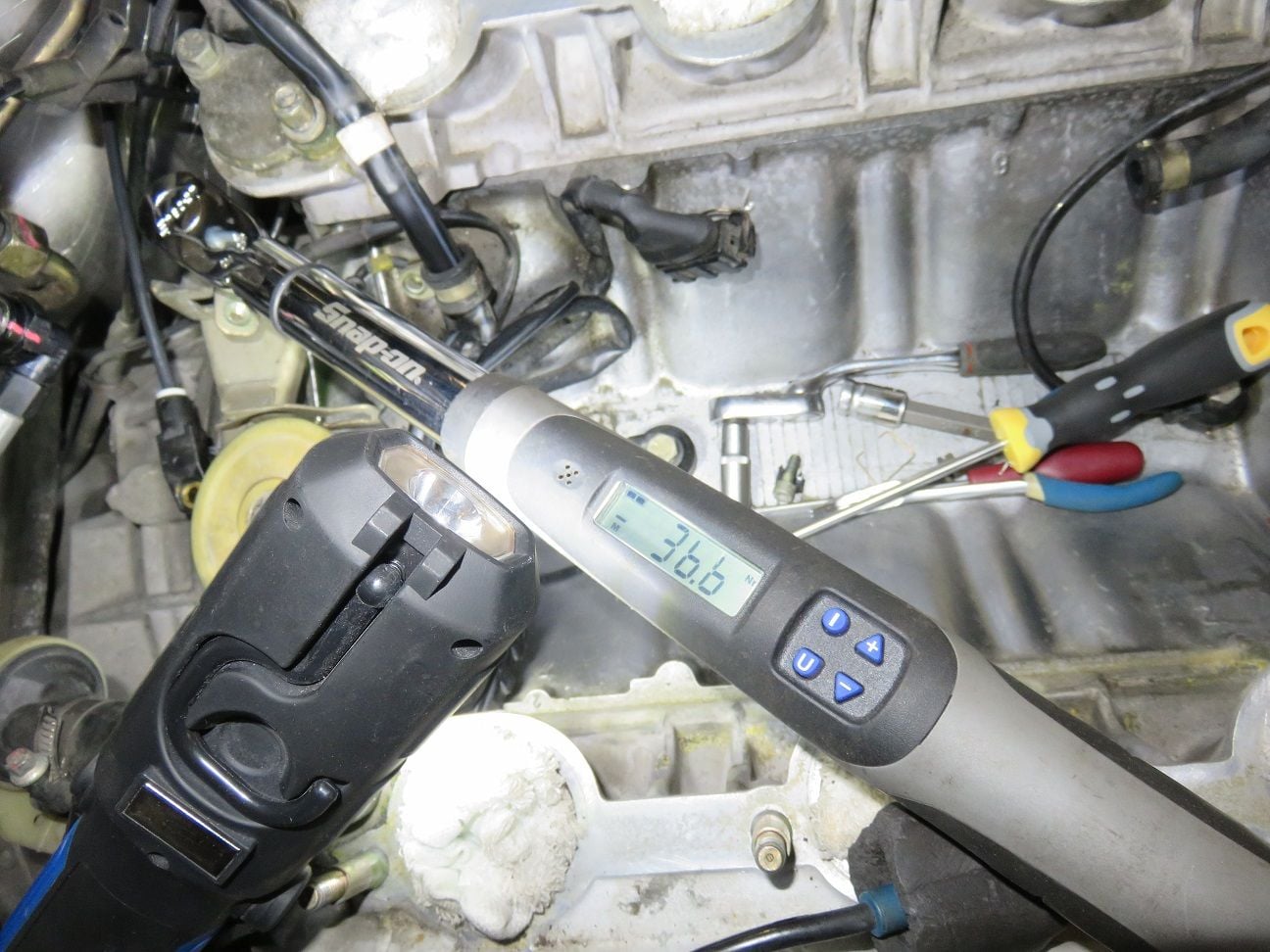
Release torque of ground point bolt MP VIII was close to the 40Nm specification:
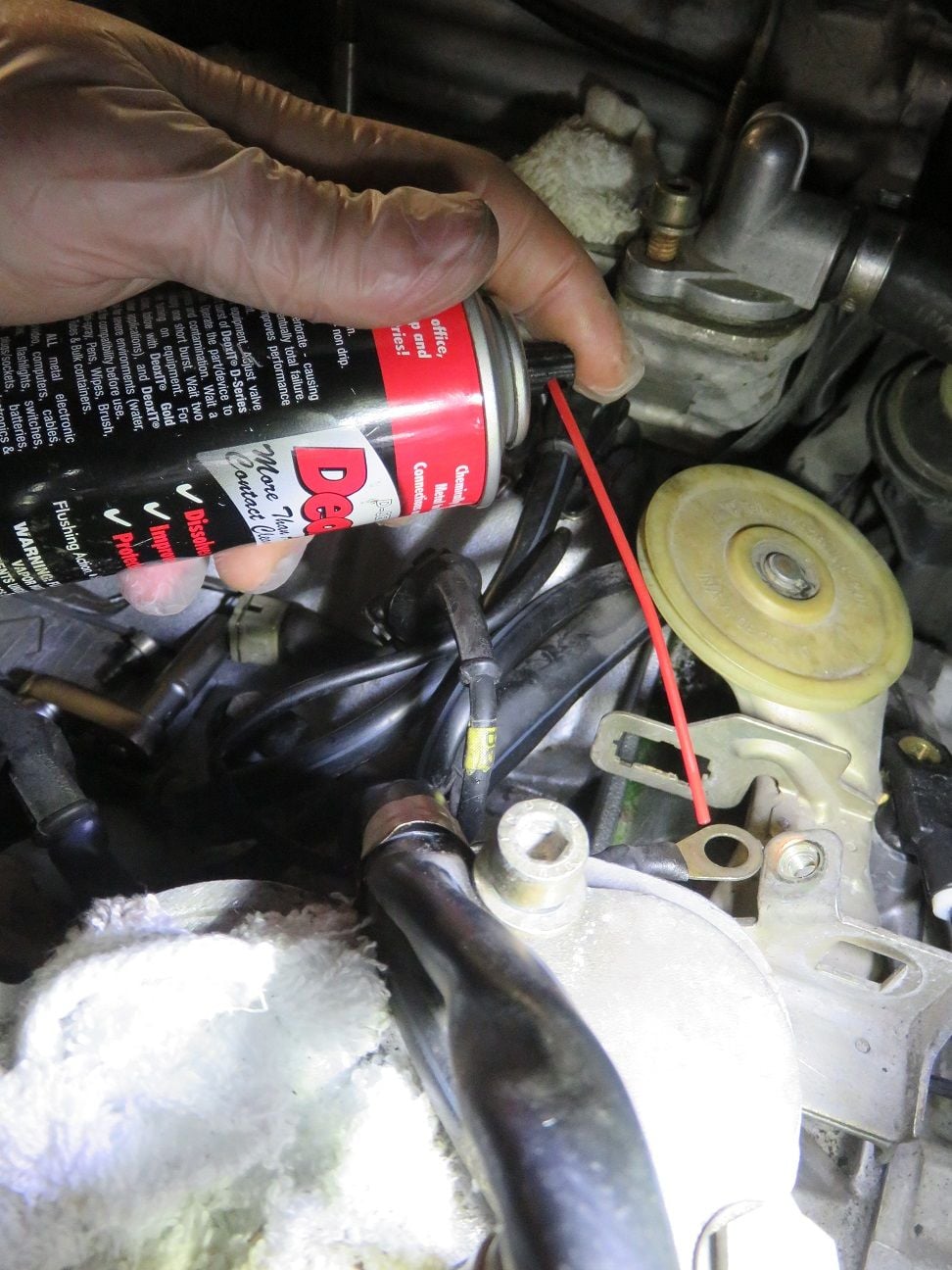
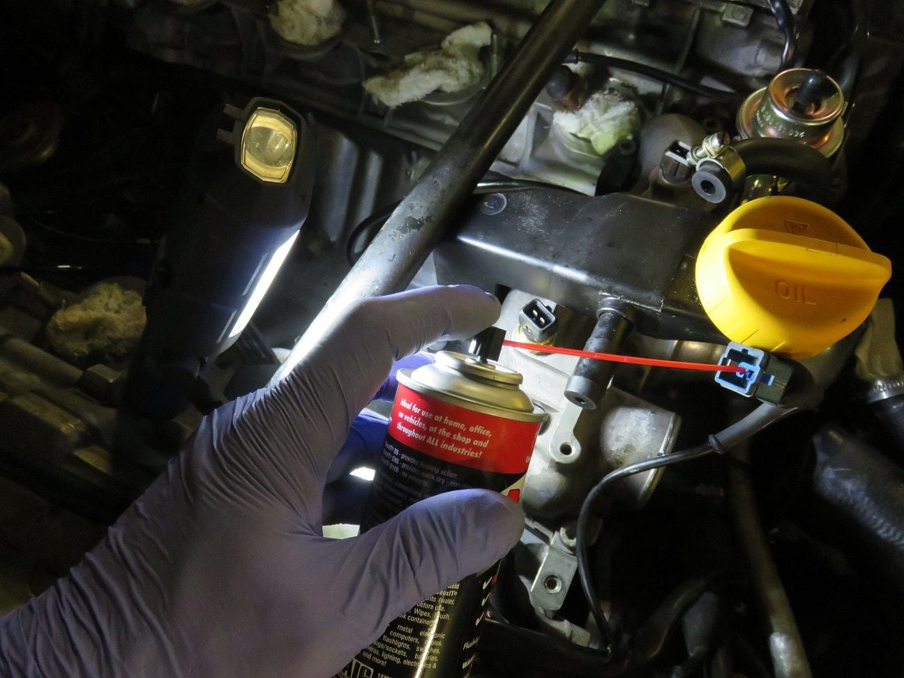
Cleaned the ground point all up with a wire brush, and a squirt of DeoXit (and then did the same procedure for ground bolt MP IX).
All put back in place, and torqued to spec.
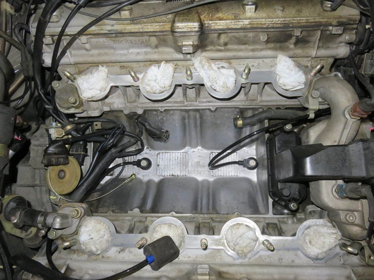
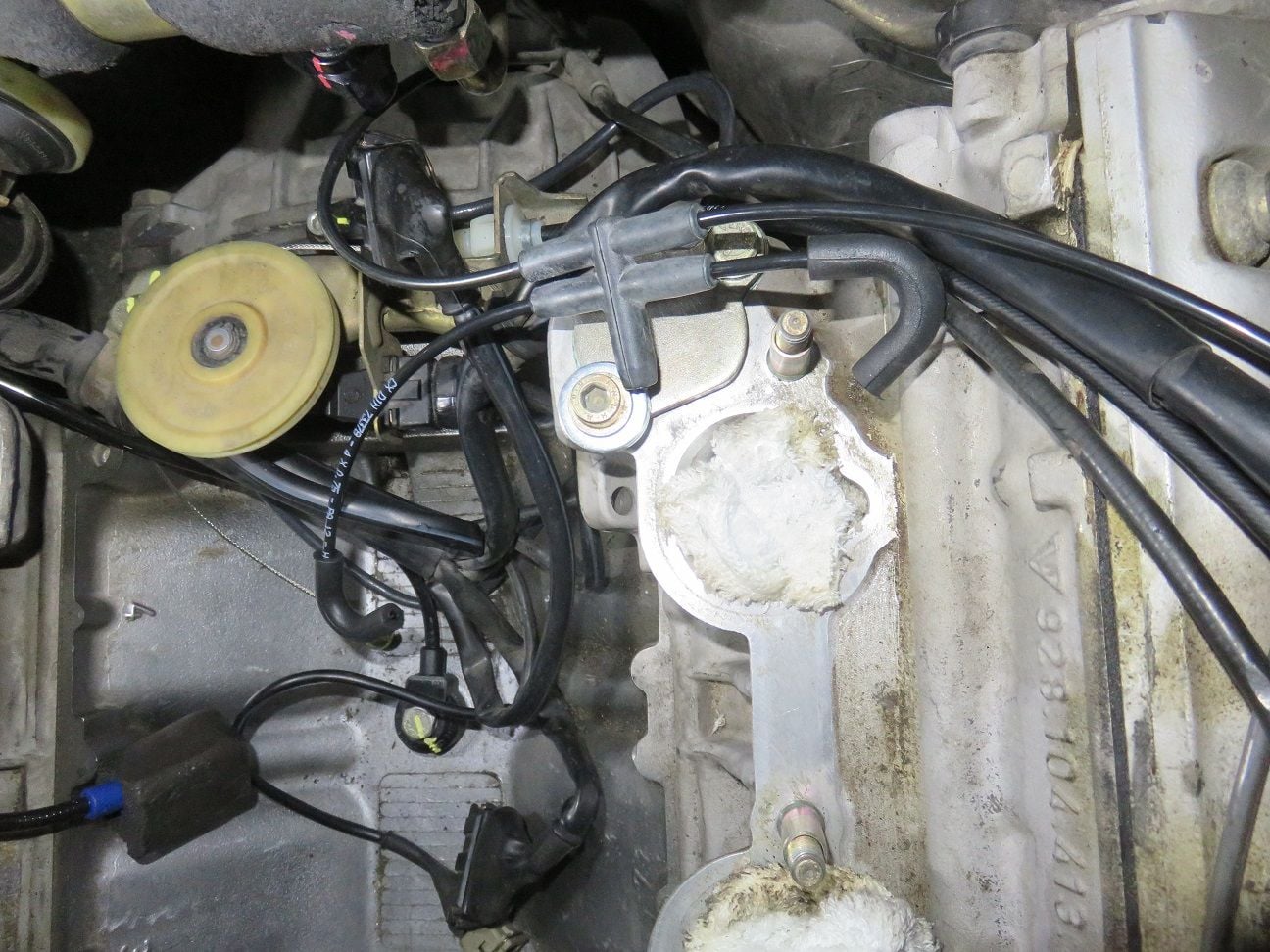
Back of the V knock sensor replacement. I used (weak) thread sealant on that bolt.
Front of the V knock sensor replacement. And I used (weak) thread sealant on that bolt too.
New knock sensors on their places.
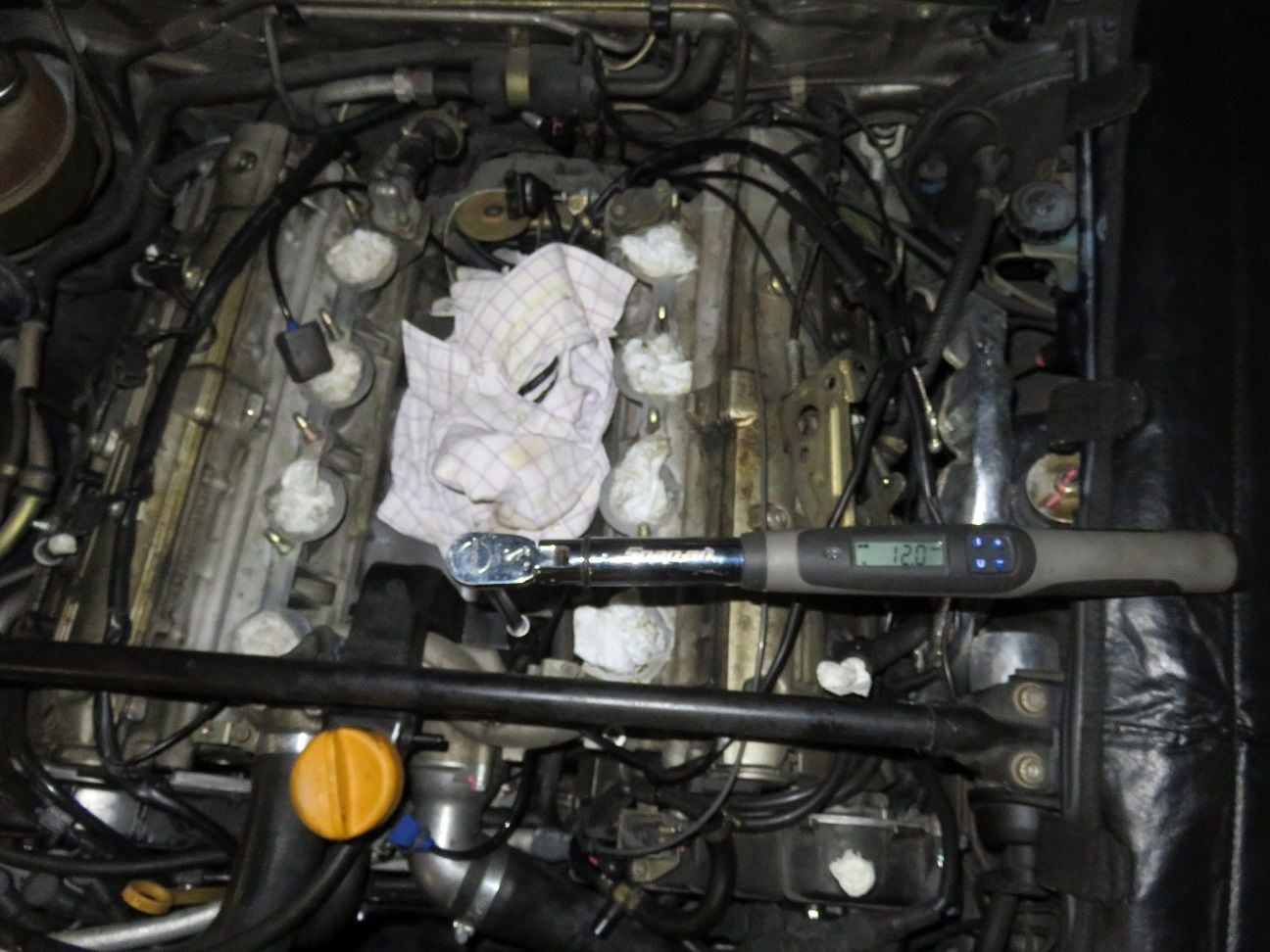
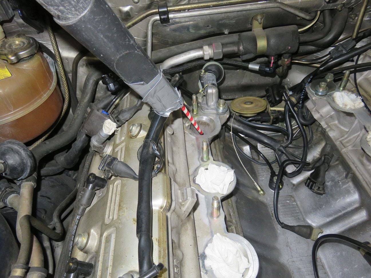
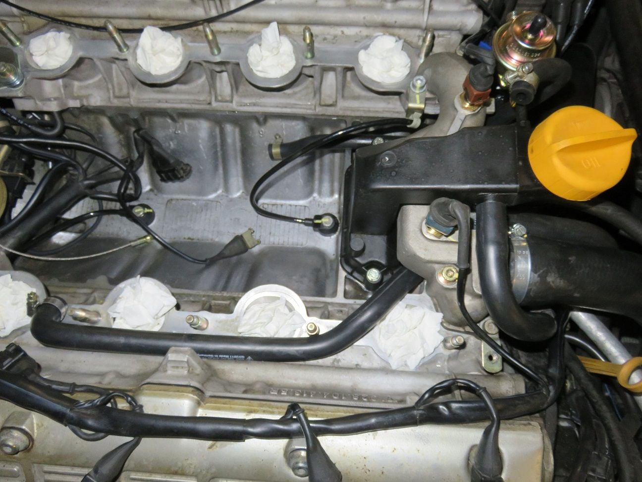
Release torque of the oil filler neck bolts was 12Nm from the factory (I have read that it is easy to over-torque these, which will then warp the plastic oil filler neck. Hence I was curious to see what those were torqued to, from the factory). Taking it out, so to install the Greg Brown oil filler neck baffle.
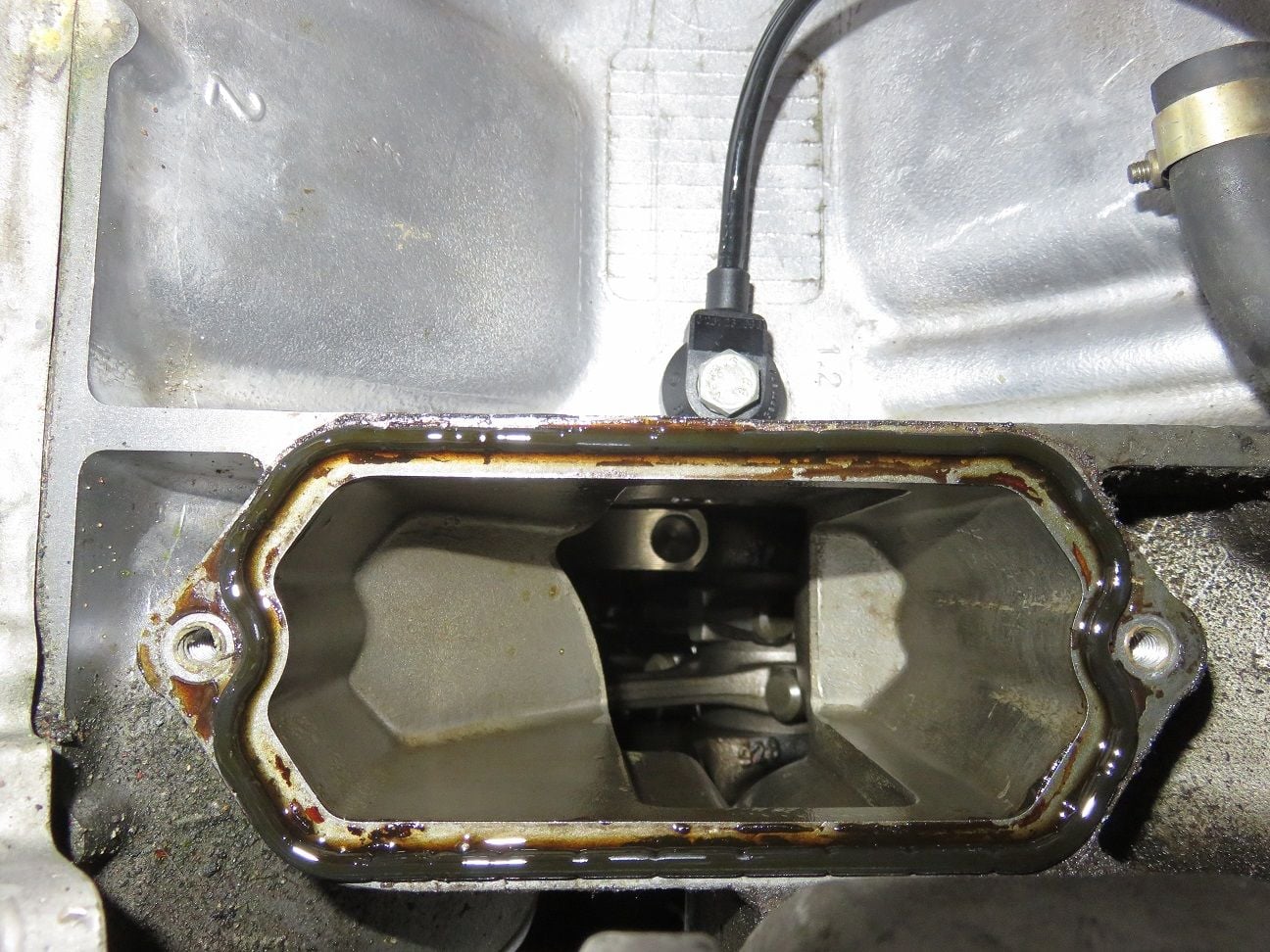
Looking down on some engine rods. And yep: I stuffed it with a new clean rag directly after having taken this picture.
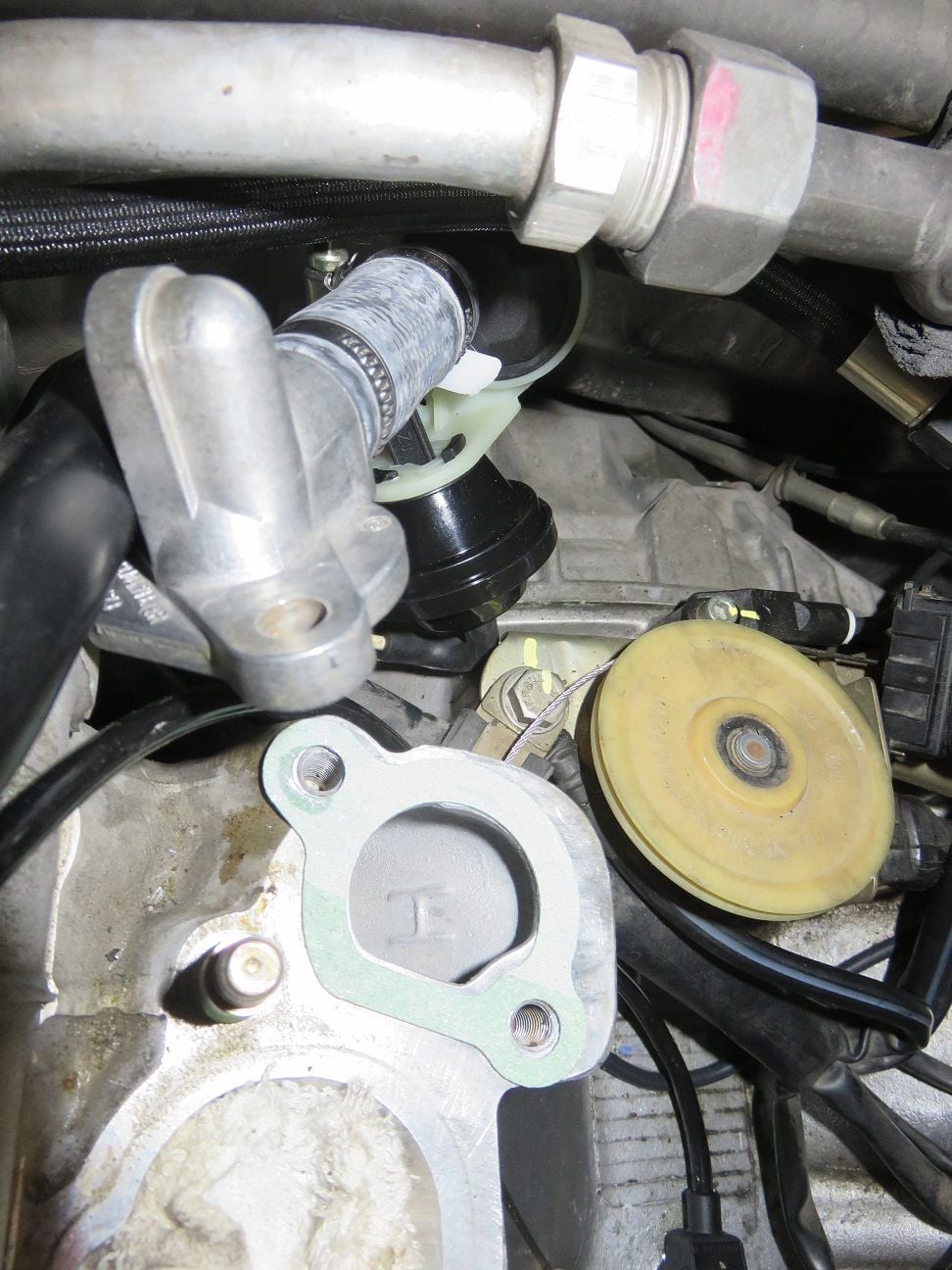
To be able to fit the Greg Brown oil filler neck baffle, the water bridge has to be removed because the bottom end of the water bridge is in the way.
Oh...crap!
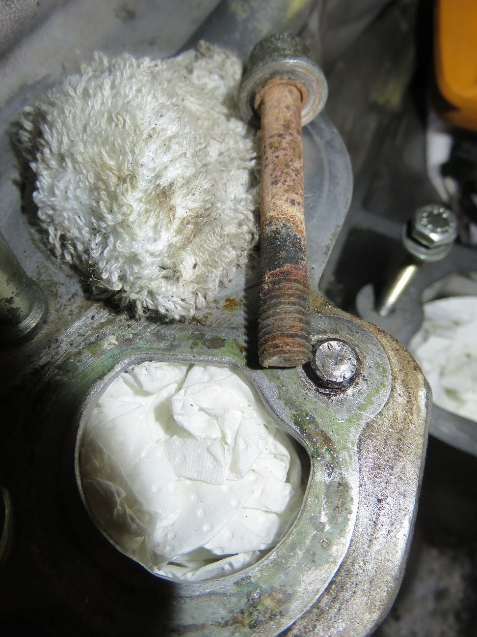
When I removed the longer 70mm water bridge bolt on the passenger side, it did not wanted to turn as all the others did. I put a bit more torque on it, and then @37Nm I heard that awful metallic "snap" sound...I never thus far had any bolt being stuck/snapping off on this car, with all the maintenance and upgrades I have done till date over the years. So this was a "surprise" to me...there is always the first one, I guess...and here it is. Caused by some drops of coolant causing corrosion of the bolt, although I could not see that from when I was trying to loose it,. This only became apparent when it snapped off.
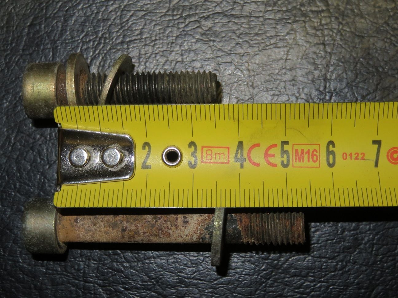
So 17mm of the 70mm total length is broken of, with about 15mm inside the passenger head.
Seems to be really corroded together...oh crap!
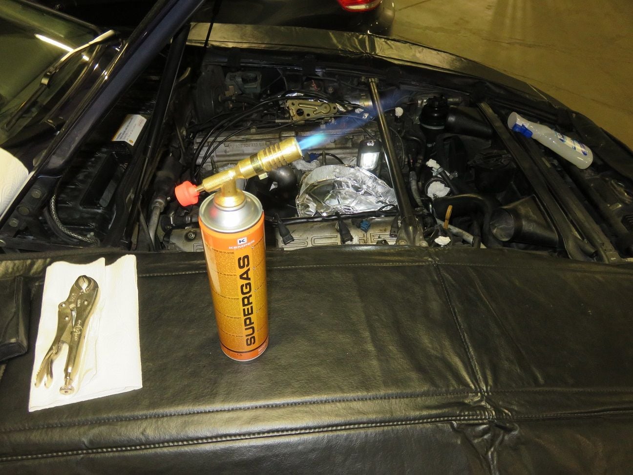
I decided to take it slow, as in: take days if needed to get this piece of broke of bolt bit out from there. So no rushing, as I only have one chance for doing this right. I started with penetrating oils and soaking it for a day, and then trying to appky heat and colt cycles and vice grips: all of that did...nothing.
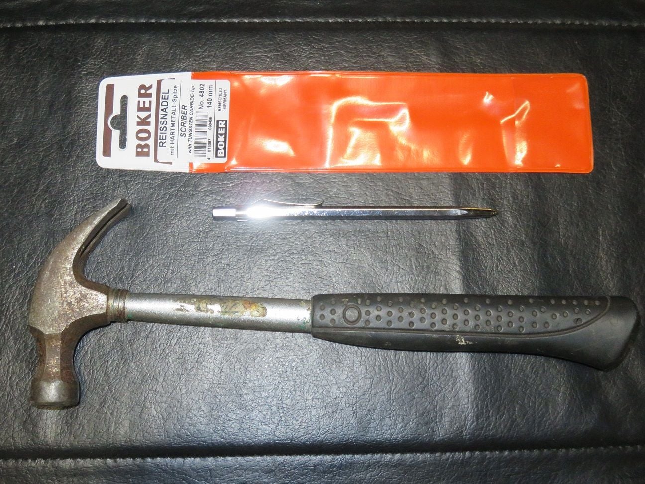
When all fails: get the hammer out! Only kidding: next route was to drill it out, hence got a new super sharp thin punch because I really needed to get the centering right.
Starting to drill the 1st pilot hole of 2mm throught it, using new sharp titanium drill bits. I used duct tape to isolate all, as well as catching the steel screw bits that got drilled out.
2mm hole drilled and cleaned up, and preparing for the next 4mm drill bit, which I attempted the next day so not to rush anything.
4mm hole drilled.
6mm hole drilling ongoing, which is the maximum size I could go (leaving 2mm for tapping in a new thread).
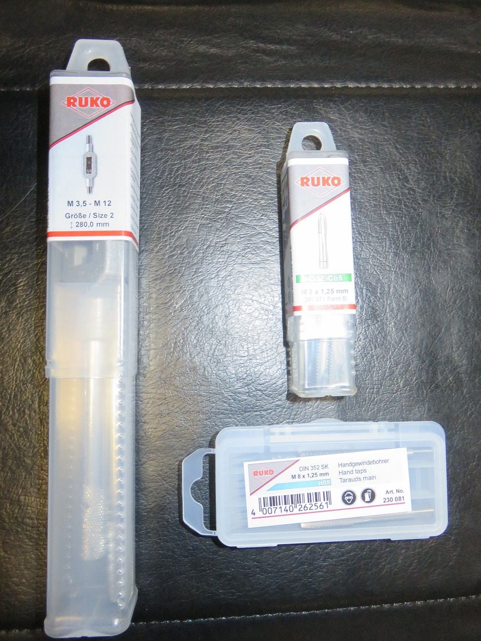
New sharp M8 taps, to do the tapping.
Q-tips can be used for cleaning up many things...including metal tap shavings from the bottom of the hole.
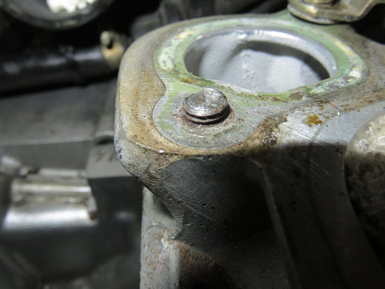
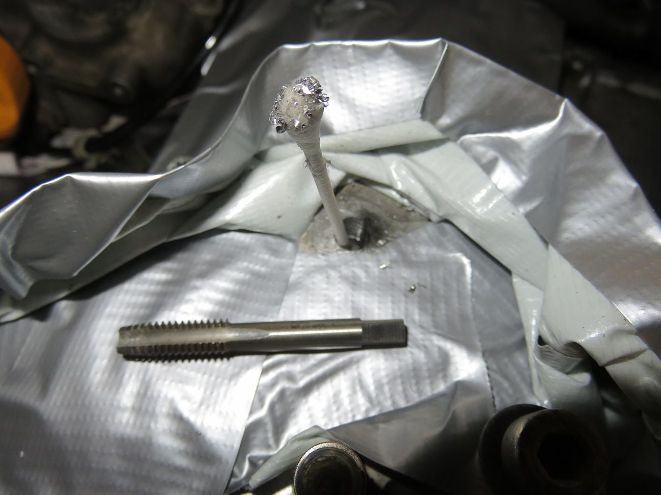
I worked super slowly with 3 different sizes taps, and after nearly 2 hours I was done: M8 final tap at maximum depth.
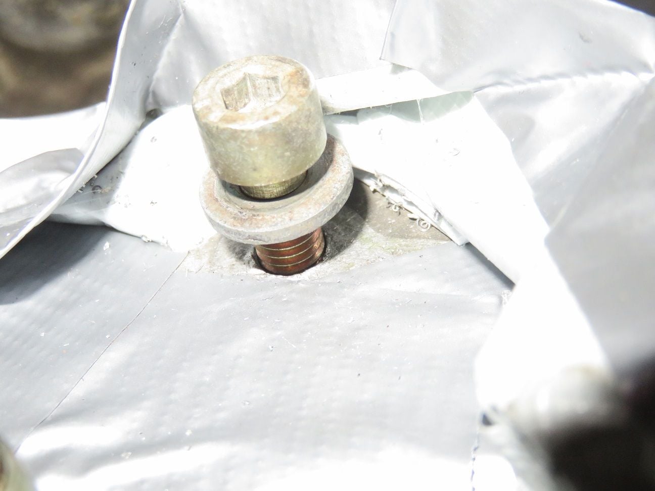
Test fitted by hand with a 35mm bolt: went in and out super smooth.
About 21mm deepp (as was about the original depth):
End result of this "oh crap!" disaster: I am very happy with this result. Set me back about 1 week.
Need to get this machine back together... Hope it all works out - seems you have replaced about everything on the way. I had very similar symptoms long ago. Tried lots of things to fix it most didn't help.
At some point I solved it - I believe it was slugs of oil (mist) getting ingested when the throttle was opened. The car never stalled but sure felt like it wanted to. You'd hit the gas, get a little burst of initial acceleration then a massive dip in power - revs drop to ~500rpm then a recovery to normal - very annoying and makes the car scary to drive.
My car now has no direct path from the crank/heads to the intake/throttle body and it never does this anymore...
Alan
Thanks Alan, for your provided feedback and insights. If you are willing to share more, on what you did exactly for taking the direct path from the crank/heads to the intake/throttle body away: I'm sure lots of us will appreciate that.
And yes: I keep on working on getting this machine back together in the meantime, and posting my progress - and occasional setbacks - here. Because as how much I love to wrench: I love driving it even more!
Oh...crap again! Or: what to do when you break something inside a coolant drain port.
WYAIT troubles:
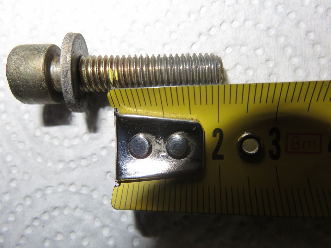
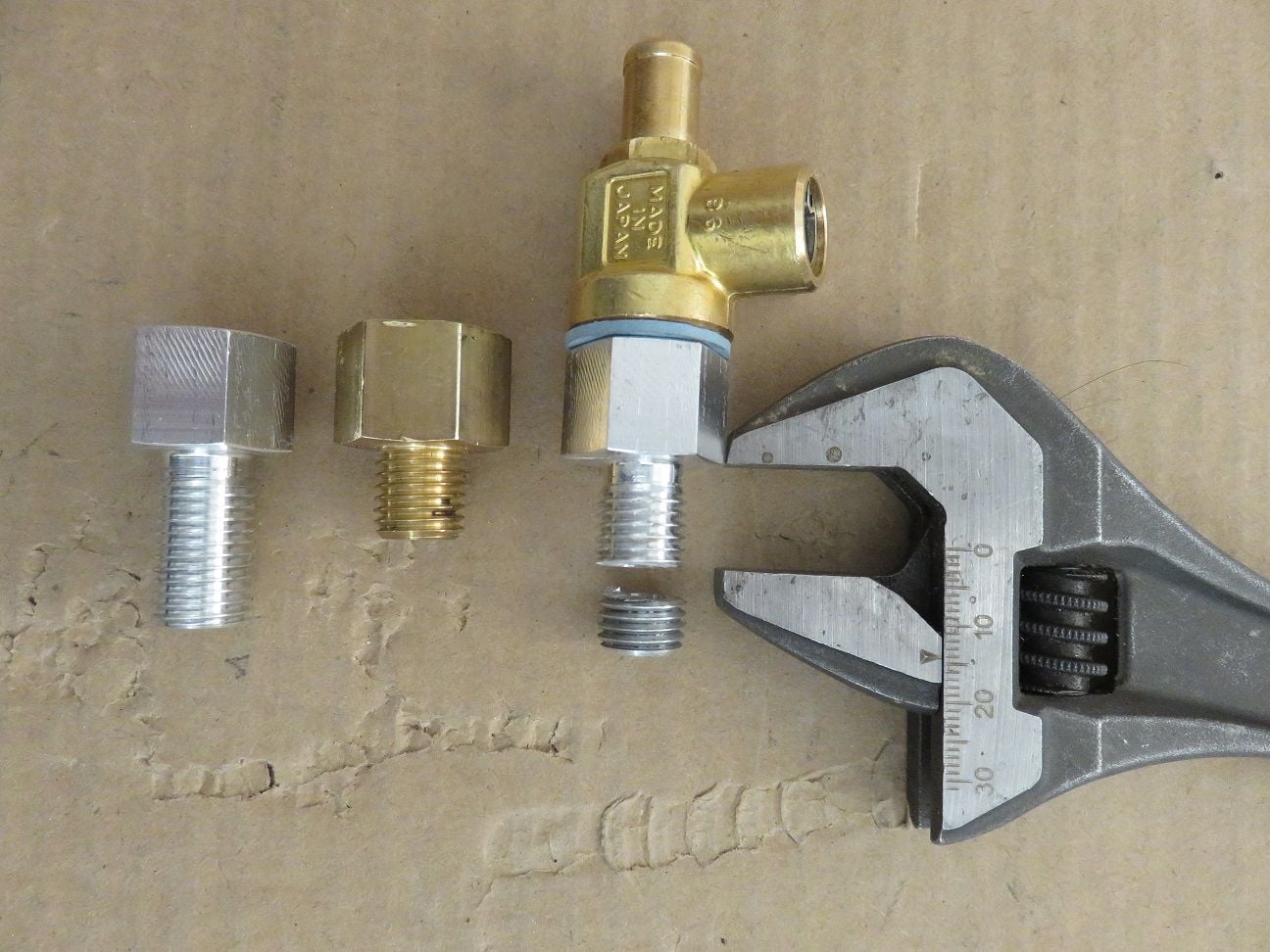
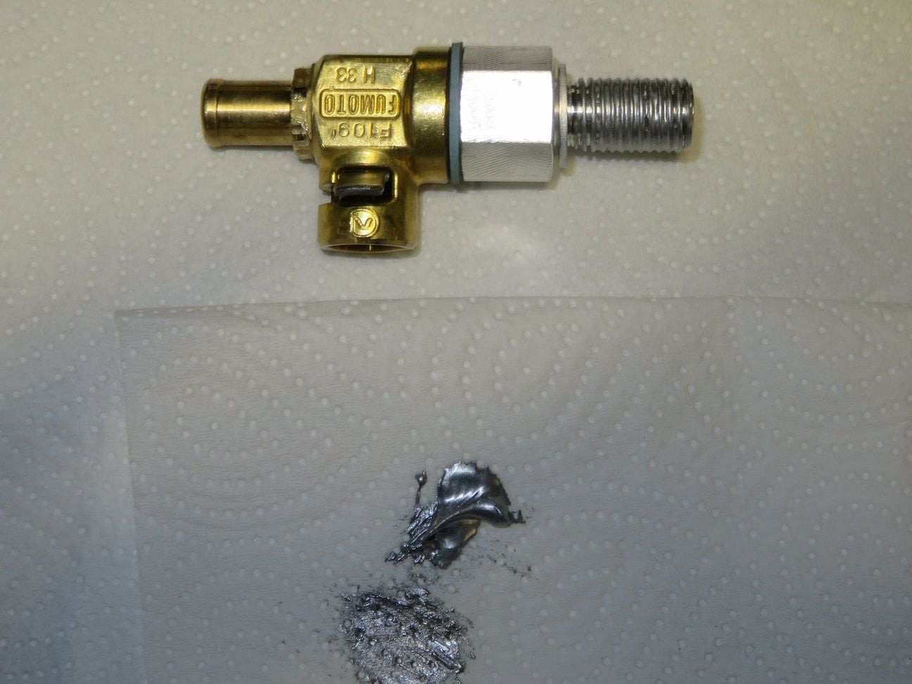
Some years (yes: time flies) ago I had bought Fumoto F109 drain valves, for putting into the block coolant drain ports so to avoid having the "coolant baths". And I also had aluminium extensions with the maximum thread of 22mm made, as my driver side coolant drain ports thread was damaged for the first 6mm or so (I had thus far made use of a longer M12 * 1.5 * 22mm bolt, which had worked fine). So I decided that now was finally a good time to put these into place as a WYAIT task.
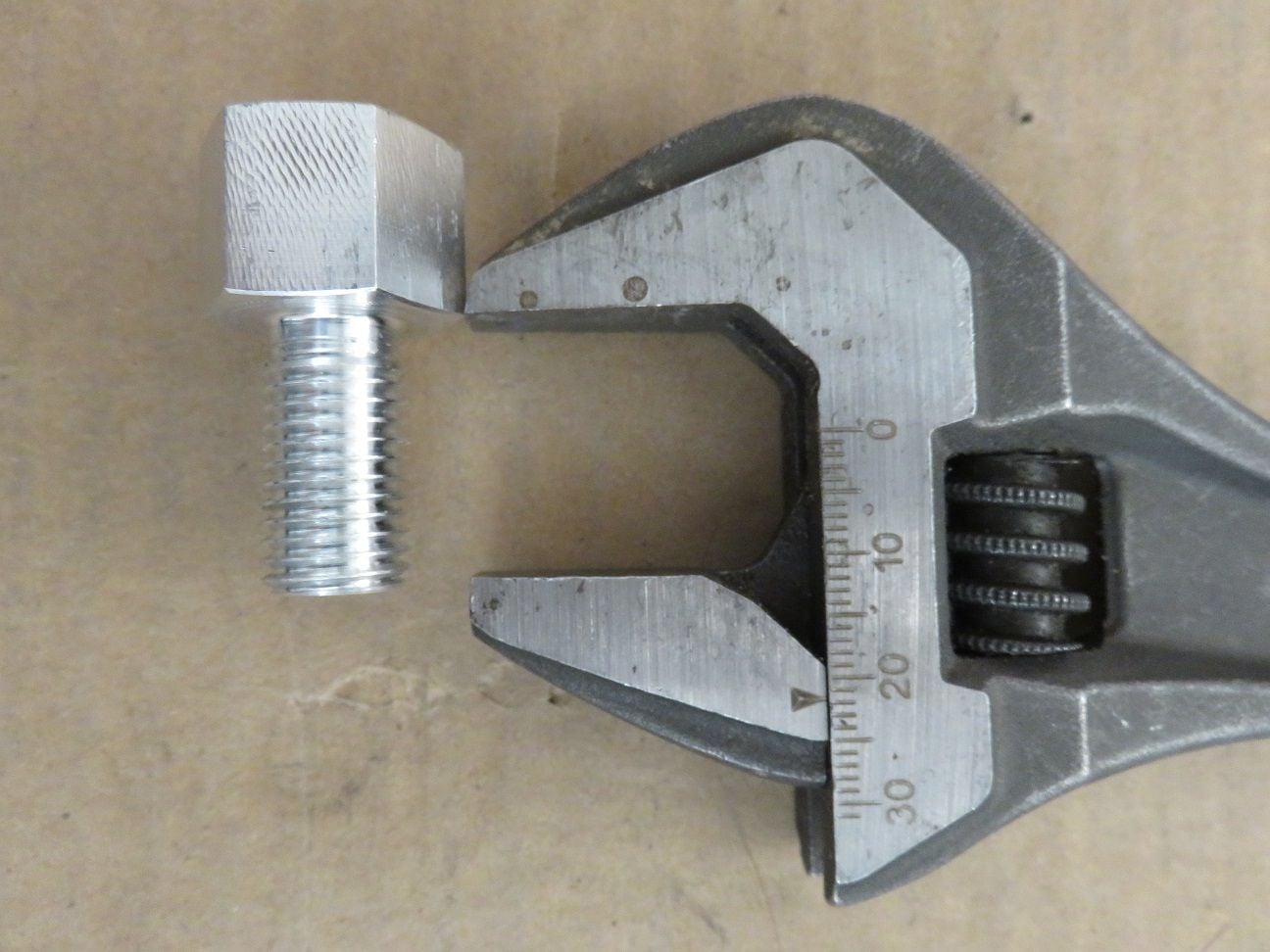
Showing the - locally in Finland hand made (I had 3 made) - aluminium extensions with the maximum thread of 22mm:
Assembled and torqued together to 25Nm, which is plenty enough because the whole assembly I would only hand tighten into the coolant drain ports thread so to have a much lower torque applied (as the WSM quoted torque is far to high, and is the main cause of stripped out coolant drain plug block threads):
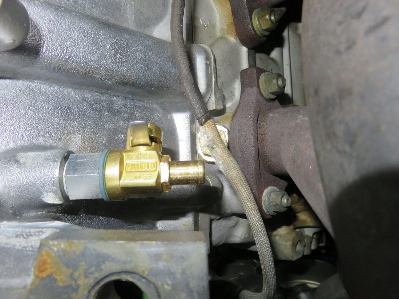
I first hand test fitted it for the dirver side, and then for the final fitting I put aluminium never seize paste on it and started turning it into the block:
All in place for the driver side: perfect.
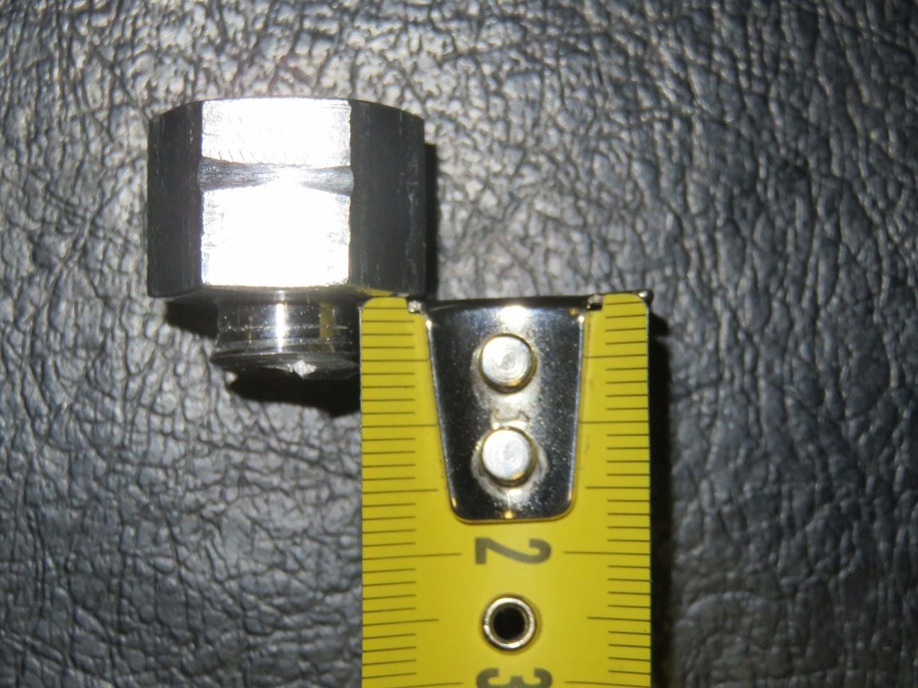
For the passenger side I made a shorter version of 14mm, as all the threads were perfectly good in there (so no need of the full 22mm length thread):
And then disaster hit me (once again during this Intake Refresh project): during the hand test fitting of this on the passenger side I noticed that it went in very tight. This surpriced me, as earlier test fitting it into the brass Fumoto extension worked super smooth.
My BIG mistake (as I know far better): when bolts or nuts feel tight when initially turned by hand: always STOP immediately and take it out and check what is wrong!
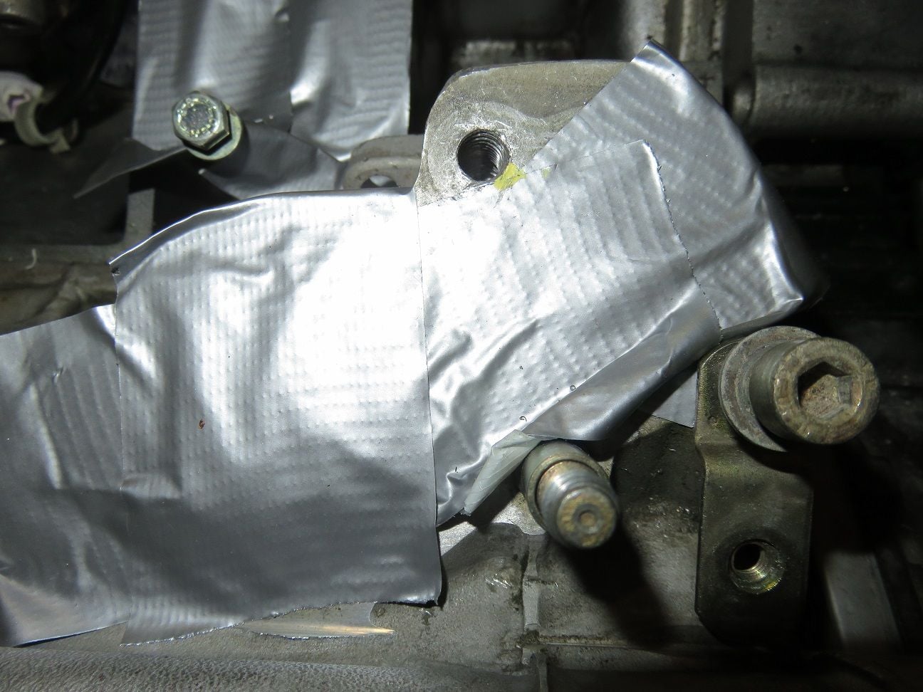
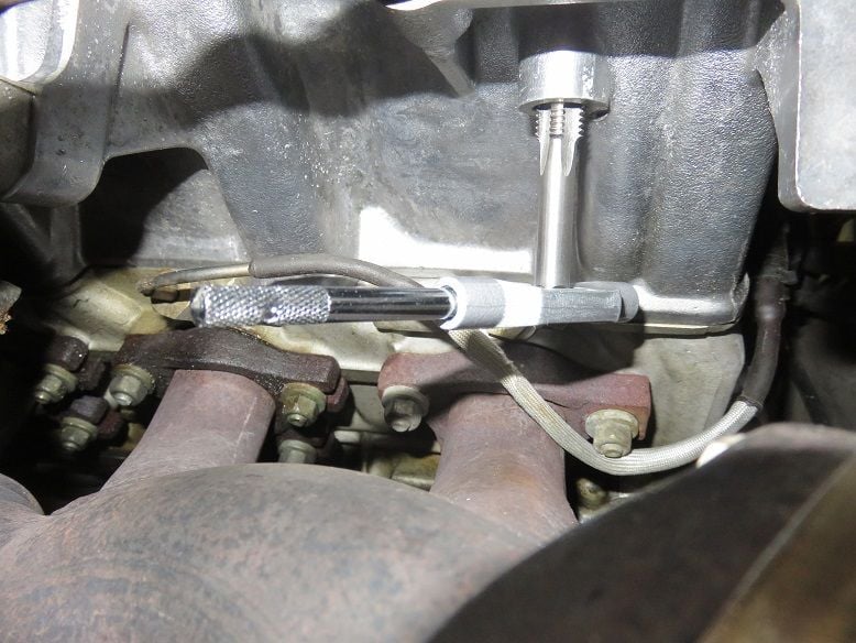
Instead I then made use of a 19mm wrench to put it in till the end, and then when taking it out I noticed that it had become very hard to turn - but I kept on turning it anyway...And then it broke off, with the hollow shaft stuck into it... Oh crap again!
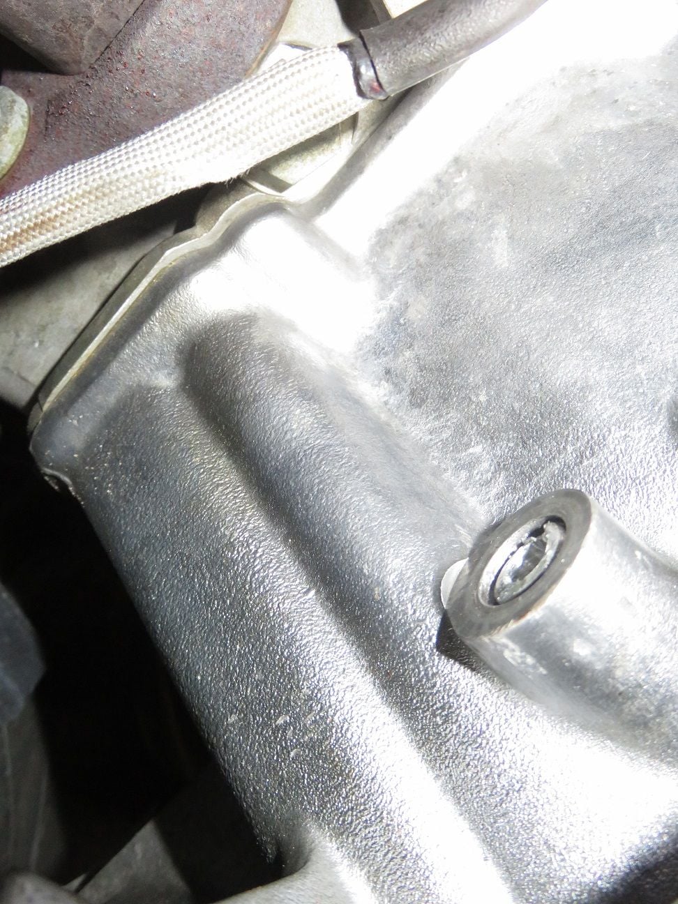
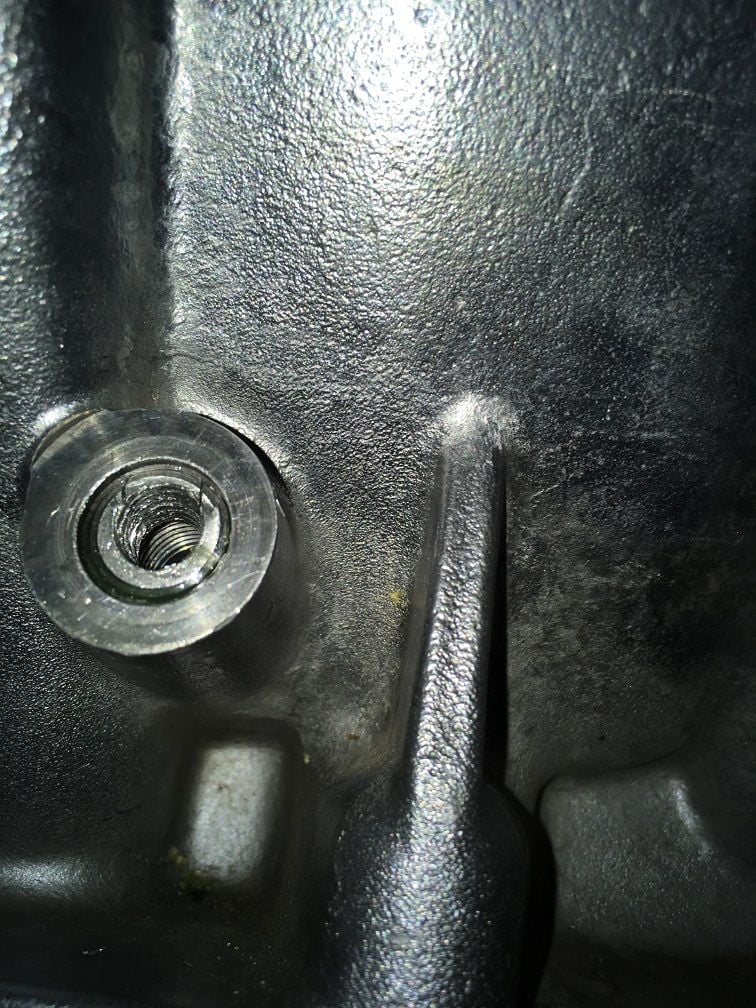
With about 6mm left over on the broken off aluminium bolt, it means that I now had an 14 - 6 = 8mm hollow aluminium pipe stuck in my passenger side coolant drain port in the block:
I tried to turn it with an EasyOut, but I felt that I had to apply far too much torque and still nothing happened. As the last thing I wanted to happen was to split open the whole coolant port, which would then need aluminum welding on the block and the engine to come out (as there are several such horror stories about that, here on Rennlist), I decided to NOT to continue to use this method:
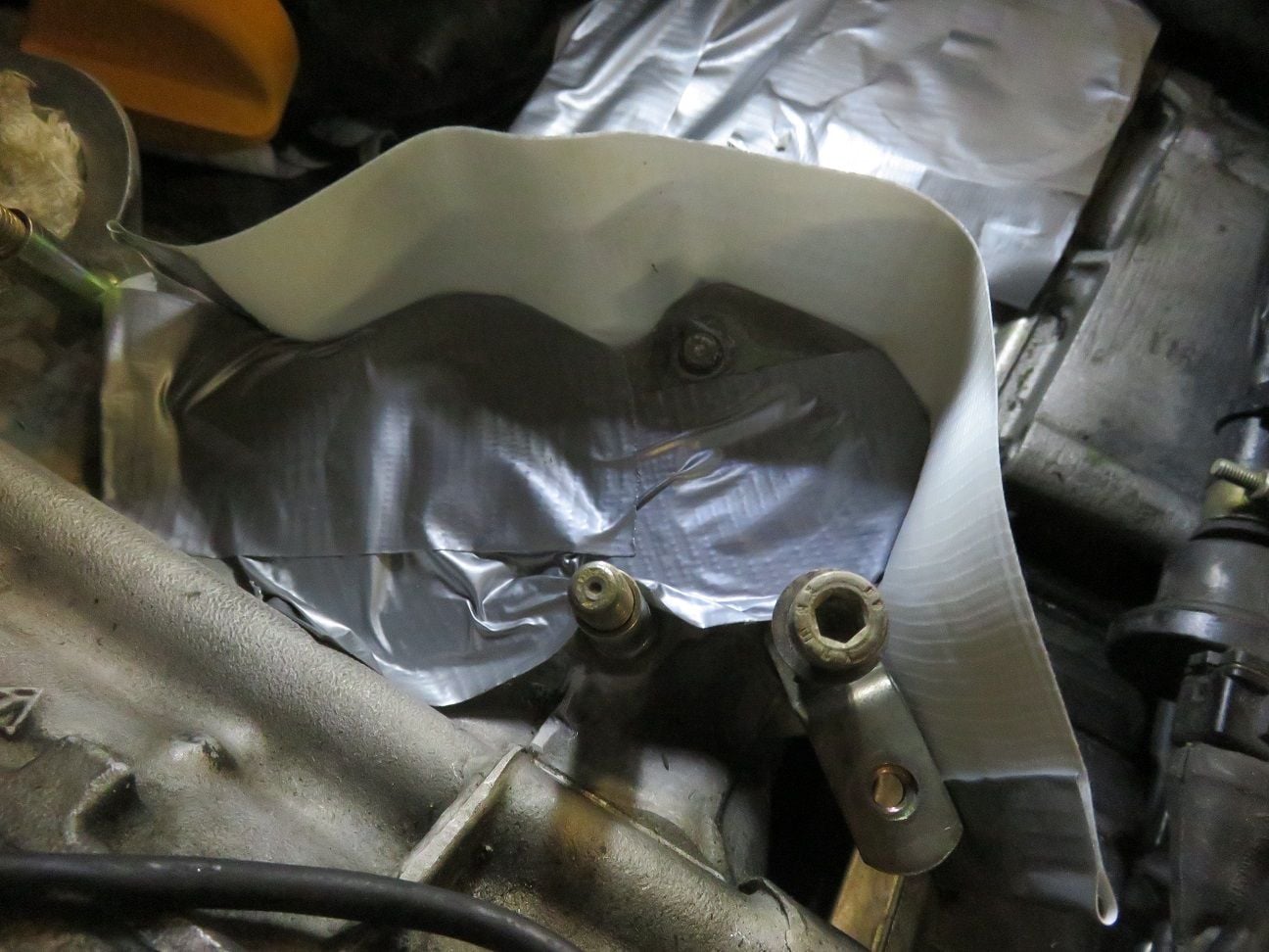
How it looked per close up picture, as taken with a camera phone:
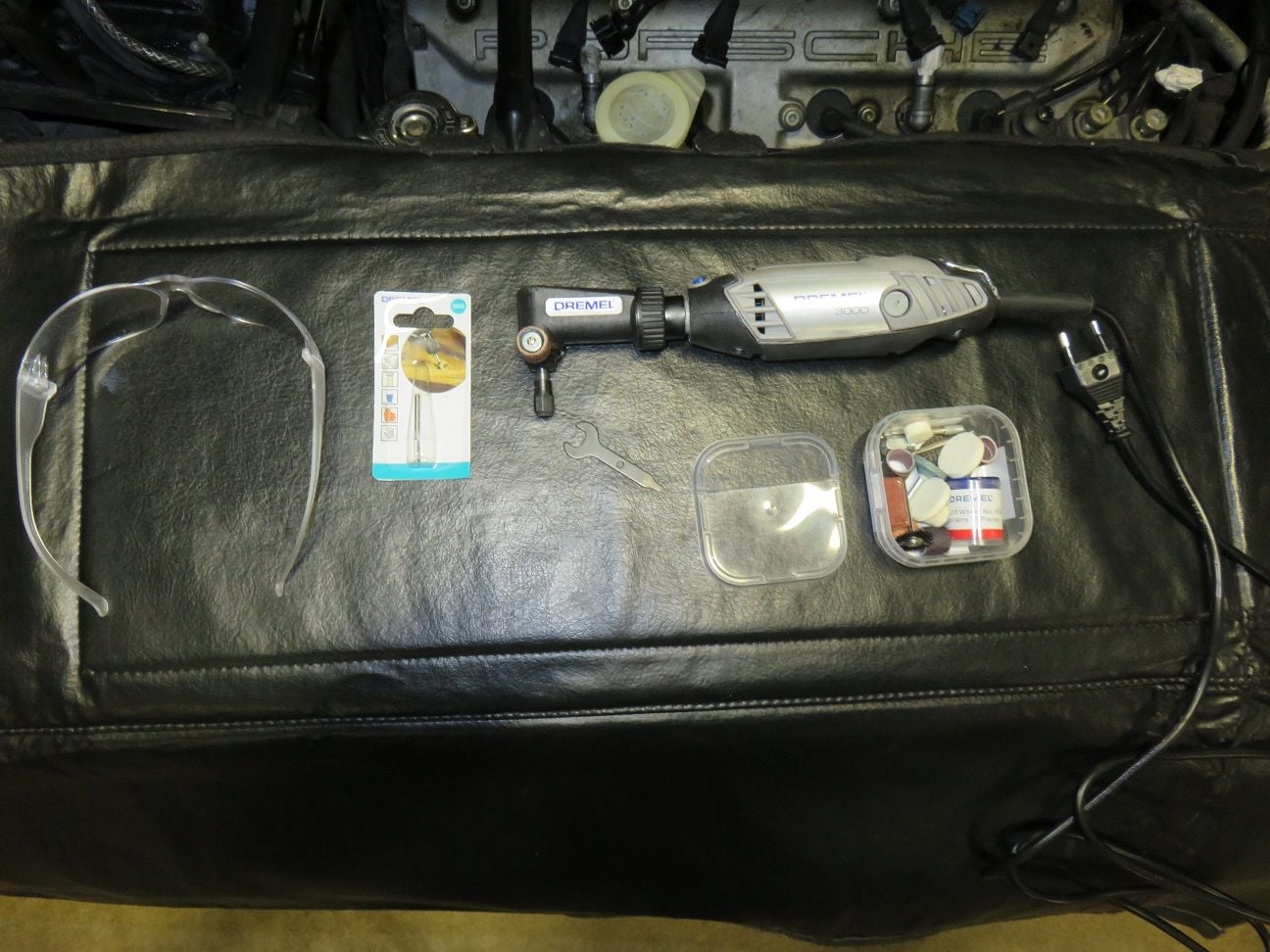
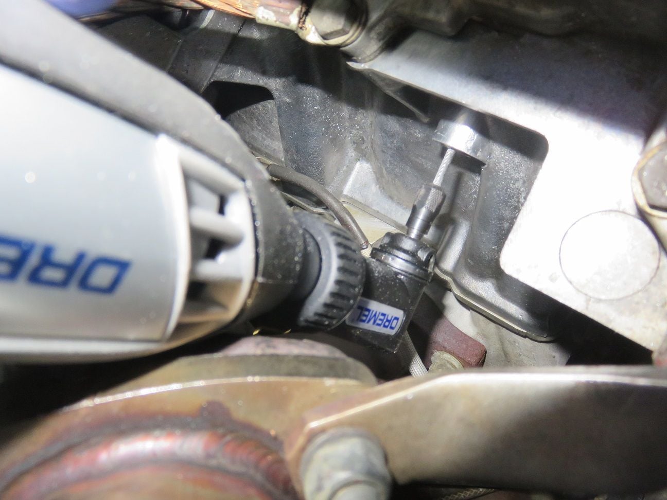
Hand filing the piece "away" was an option, but would no doubt take a very long time. Hence I tried to get a drill in this super limited available space: and what just fitted was a 90 degree angle piece attached to a Dremel:
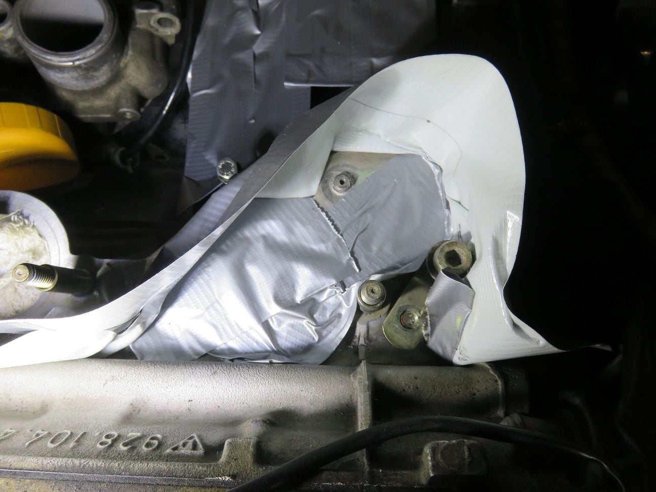
I had first tried a cylinder diamond cutting bit, but that took near "forever" on cutting anything. So I changed to a 9901 thungsten carbite cutting bit, which worked indeed faster. I applied circular motion so to try to remove the material evenly everywhere (which was and is far from easy, as all has to be done by feel only while cutting it). Hence me cutting for a minute and then removing material, and then taking a picture with my (thin, so fitting into the space) phone camera to check on the progress all the time:
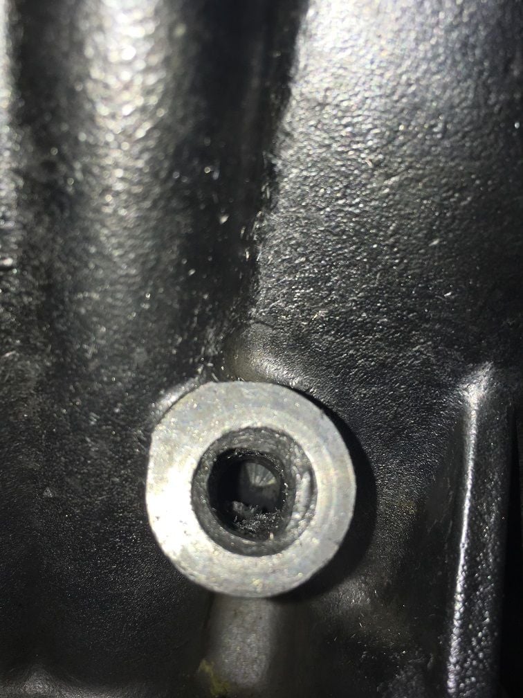
After many hours of as careful cutting as I could, I ended up with this view and I decided it was time to start using the taps...
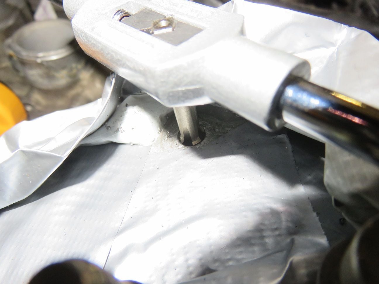
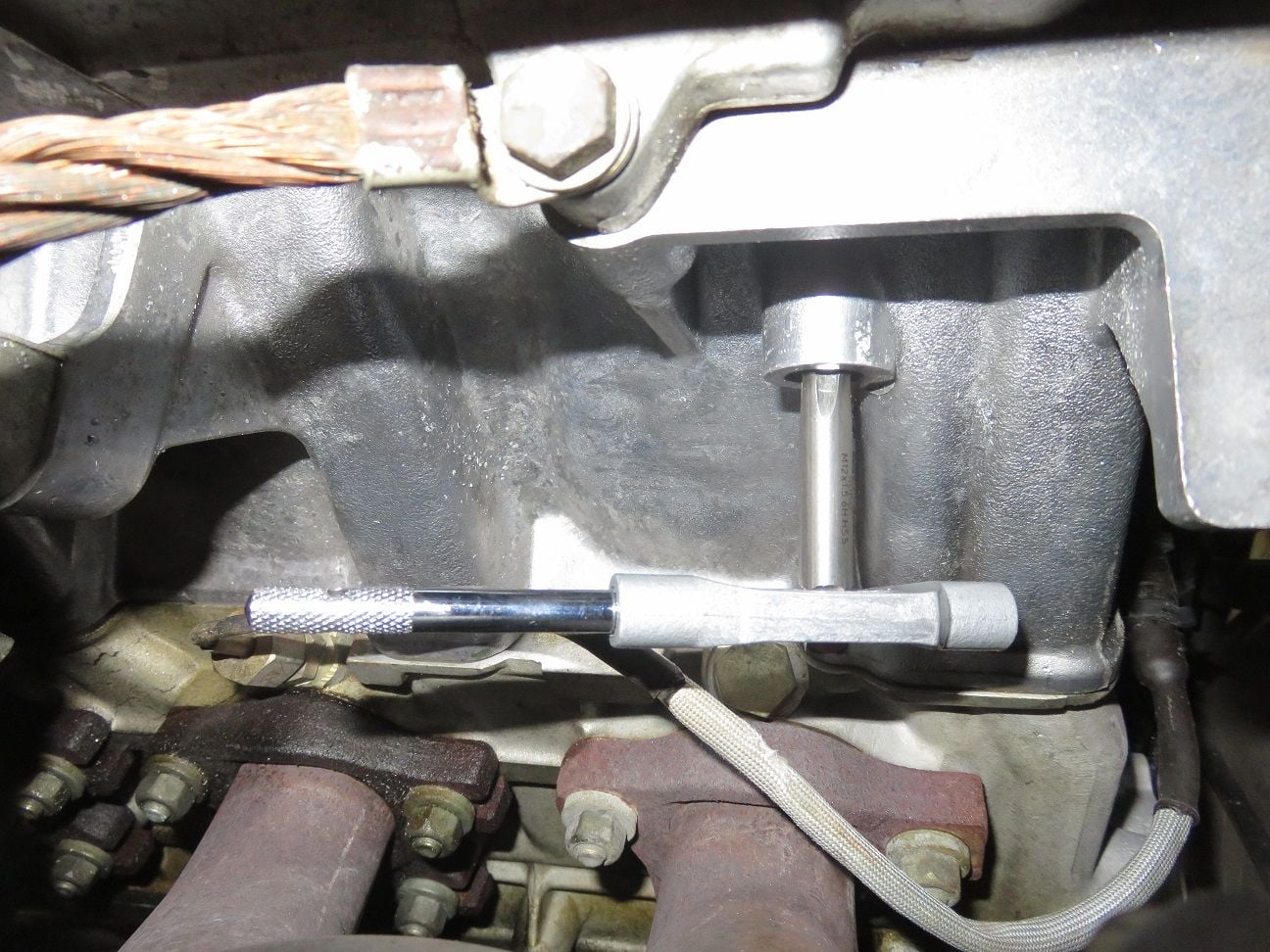
Initial M12 * 1.5 tap in use:
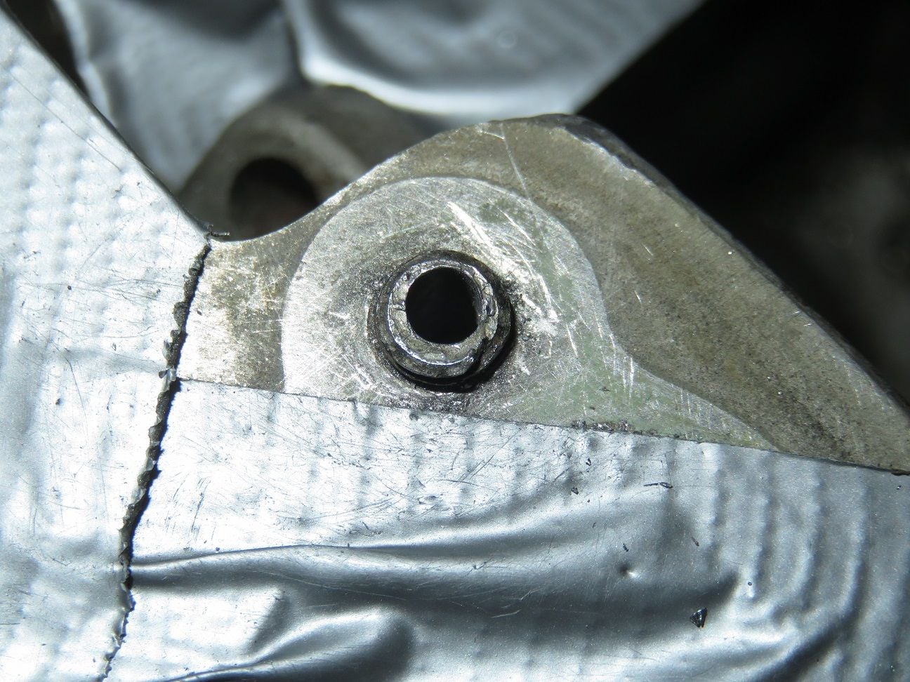
Final M12 * 1.5 tap completey turned into it = 22mm+ deep:
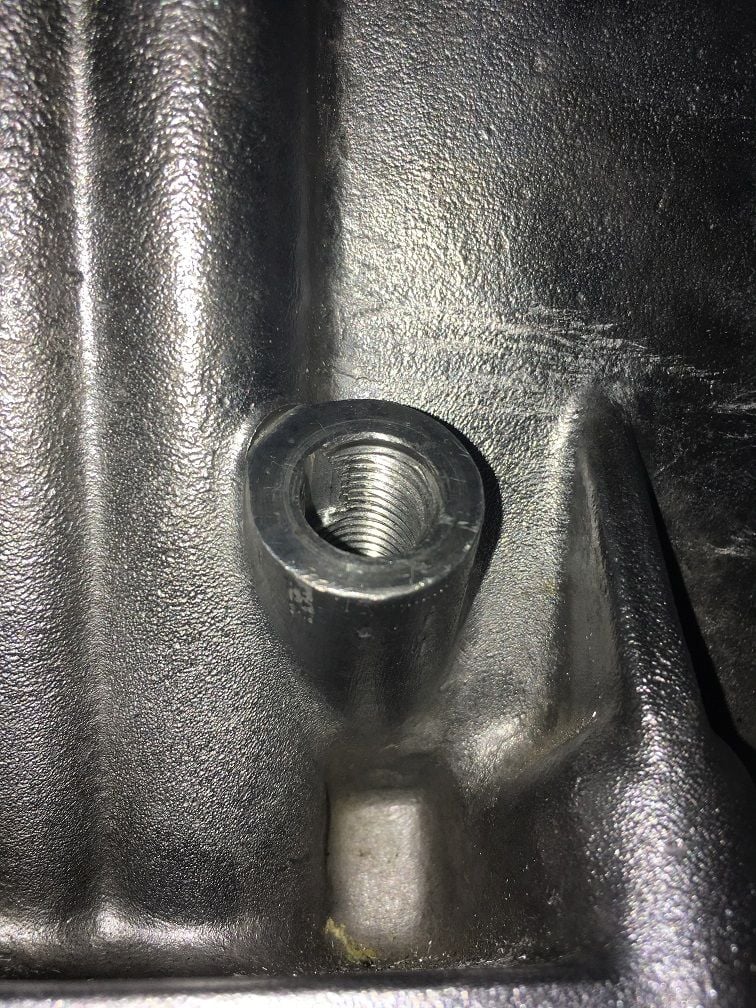
Final result: even though I obviously had cut some of the original starting thread away, I was super pleased with this end result: plenty enough original thread "back" (and no need to take the engine out and/or having to weld the block...)!
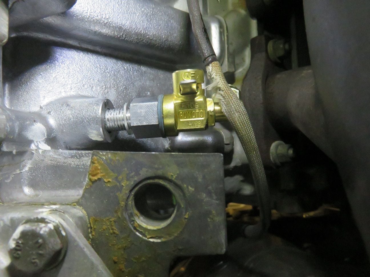
Test fitting the passenger side (and lucky I had 3 long aluminium extensions made, instead of 2) again, 2nd attempt:
All in place for the passenger side: perfect and nothing seized nor broke this time:
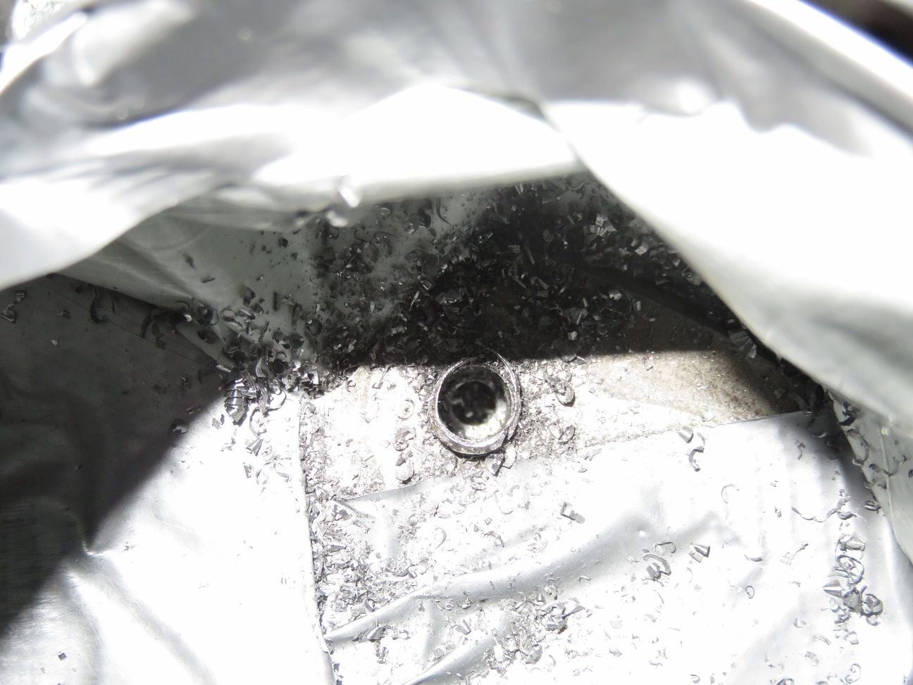
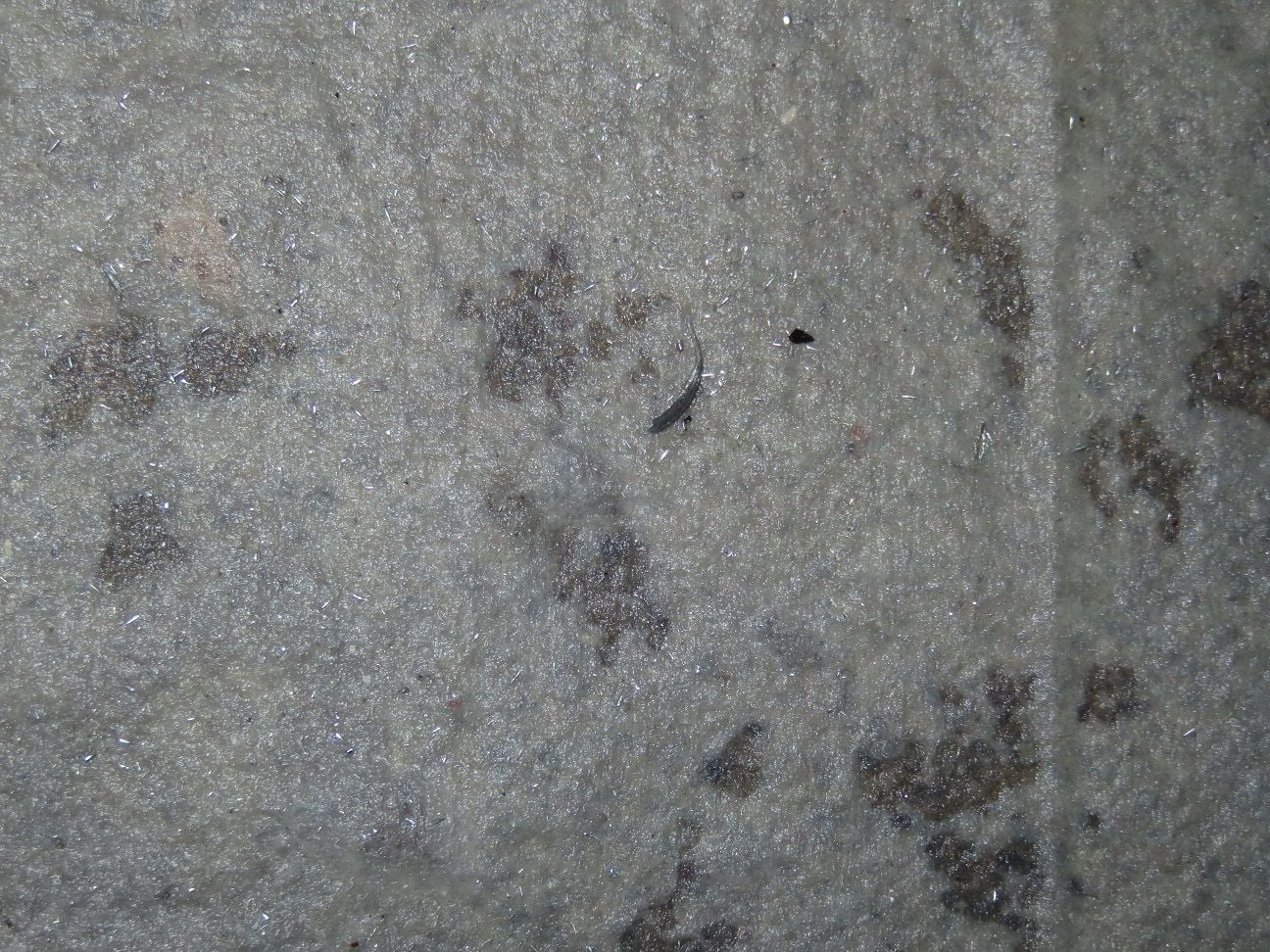
Flushed it 3 times with 4.5 liter of water each into the block, so to get all the aluminum shavings out. This came out with the first flush, flushes 2 and 3 had absolutely nothing in it anymore:
Close up of the first flush, found shavings:
I hope that documenting my dumb made mistake here, that in the future it might help somebody else with a similar self inflicted problem - on what to possibly do next. Patience was key here, so to not make it even worse.
And now back with my intake refresh, and putting all back together again...
Did you make your own oil control or buy a system from one of the vendors....just wondering since okc gts is for sale....
I made my own. It is a combination of replumbing the head ports (all 4 installed and drilled out), the rear 2 are fresh air feeds from the airbox (bottom) via one way (in only) and vacuum limiting valves, the front ports are also 'in only' ports fed back from the oil separators. I also plugged the throttle body ports on the passenger side and all the oil filler ports. All evacuation from the crank now comes out the oil filler which is ported (big) to a vacuum pump that replaces the air pump. It has a Greg Brown separator in the block under the filler. I no longer use this for oil fill - I have a new separate filler for that. The vacuum pump feeds a small high velocity air oil separator (Alfa Romeo sourced) with vacuum drains recirculating to the front head ports. This small AOS strips most of the oil to protect the Provent from over oiling. The crank gasses then slow down into a Provent 200 with its oil drain going back to the oil pan. The gas exiting the Provent is very clean and goes back into the Passenger side airtube feeding the airbox (a larger port where the Air Pump bypass used to go) - so this is ahead of the Air Filter. Never seen any indication of oil in the outlet
It was a ton of work and a very tight fit with lots of plumbing - but it works. I would not really recommend anyone follow this path - you have to make stuff, and heavily modify stuff - welding, brazing etc
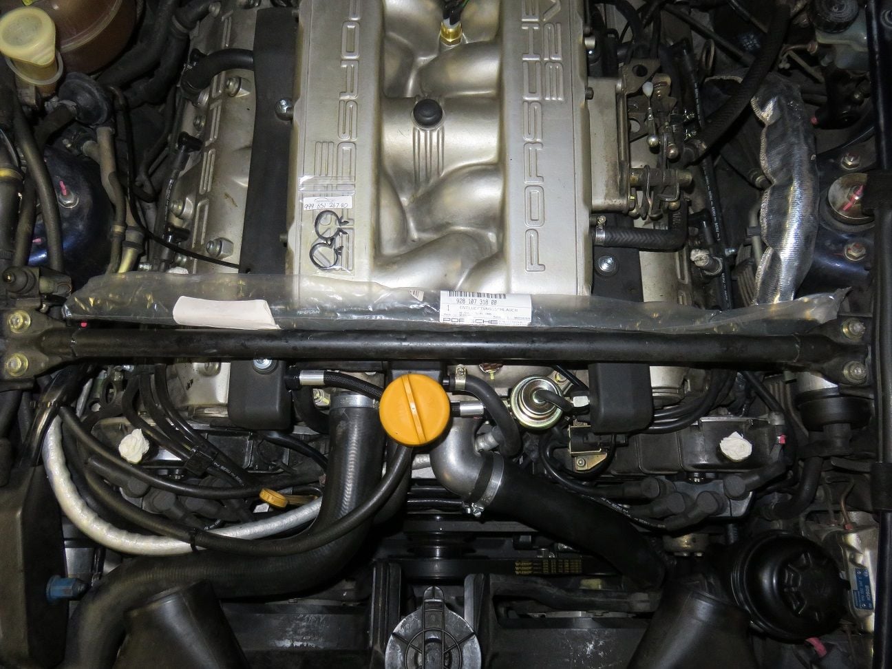
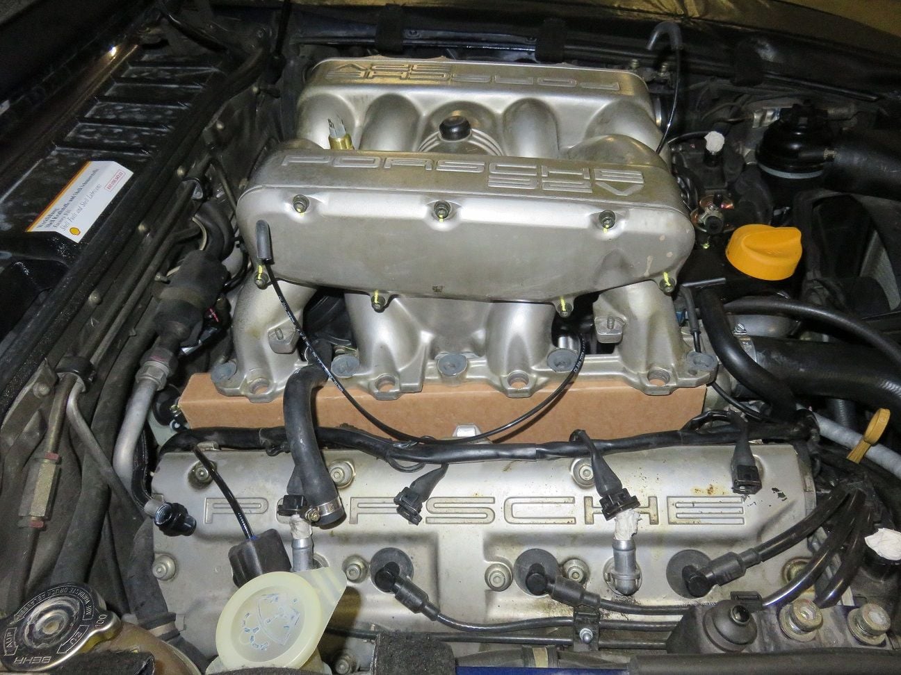
During the last weeks, I have completed my intake refresh project - even though not having solved all my original problems yet!. Hereby the additional steps as I did in pictures, as it might help future others doing their intake refresh project as well.
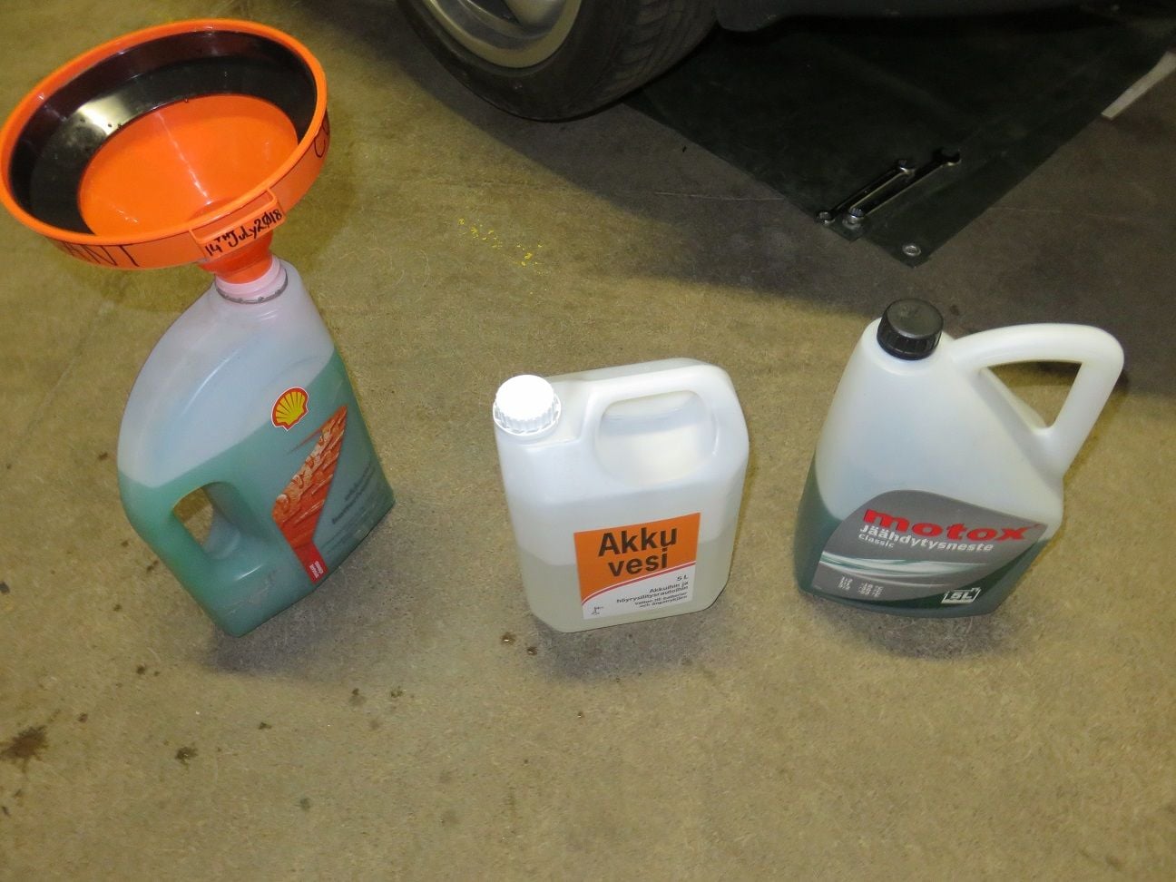
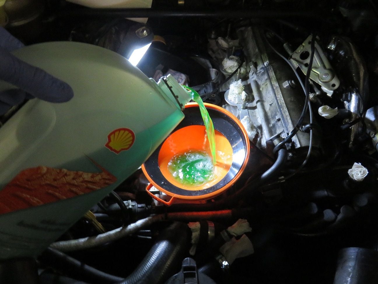
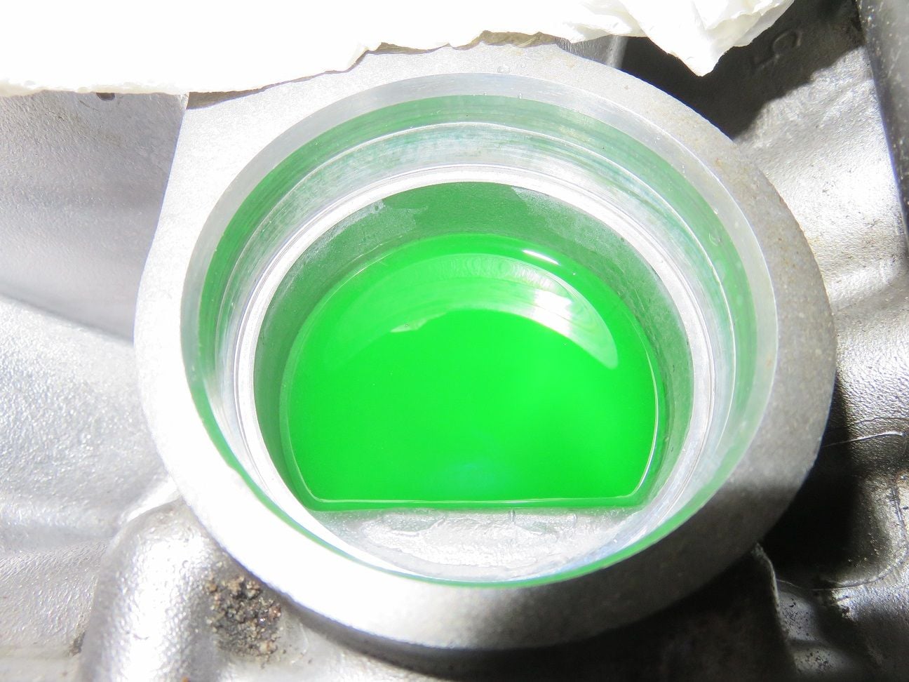
Following Dwayne's guide, I also decided to fill the block with coolant, using a 50% distilled water + 50% coolant mix (as it's a bit colder in the winter time that might take 6+ months, here in Finland):
Coolant mixture going in:
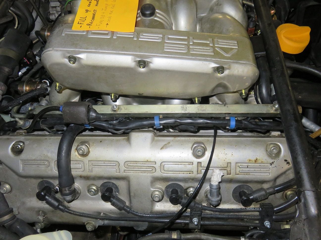
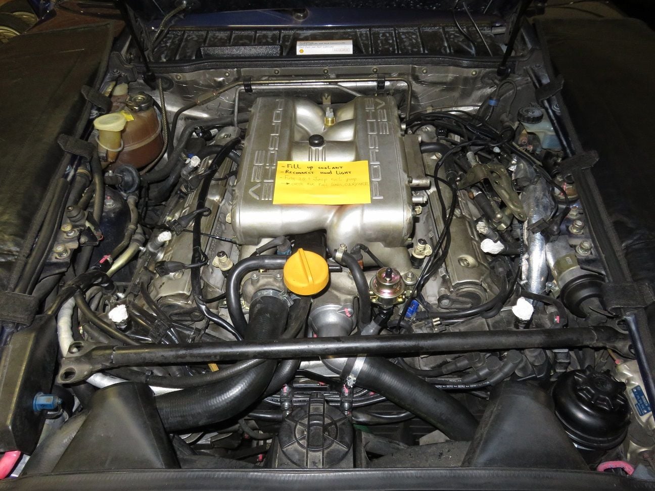
And coolant filled up (and wrote myself a PostIt note, so to remember topping up the coolant before the final start-up):
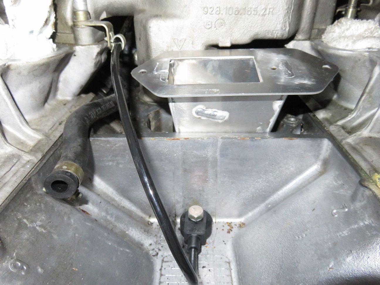
Putting everything ready for the Greg Brown oil baffle + water bridge re-install:
New oil filler neck gasket:
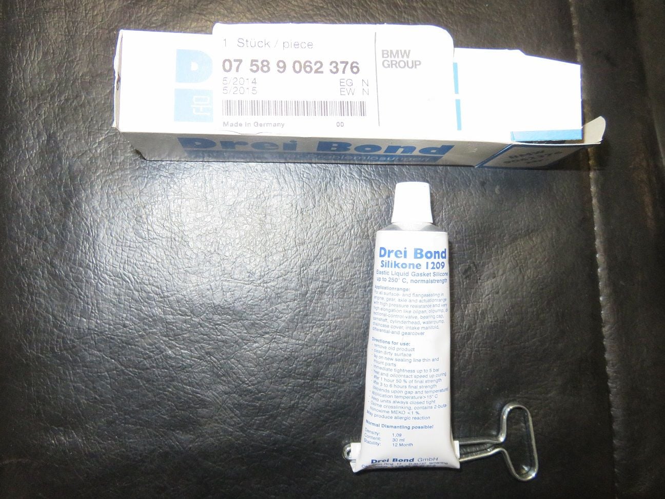
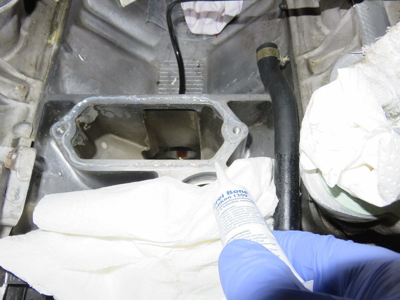
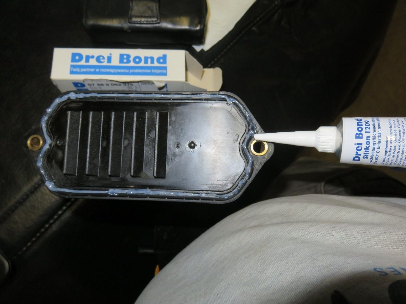
As recommended by Greg Brown: using Drei Bond (bought at local BWM dealer for about 10€ a tupe, BMW part nummber as per package: 07 58 9 062 376).
Applying a thin layer of Drie Bond on the oil filler block opening:
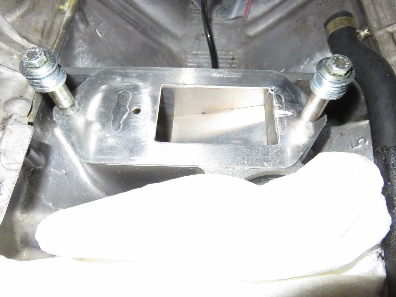
As Drie Bond has a quick curing time and I know I work very slow, so I put the Greg Brown oil baffle in and screwed it temporary in place so it would harden while I work on installing the water bridge properly back in. Improvised a bit here, as I did not had short length M8 bolts around - but did had plenty of washers.
Water bridge put back in place:
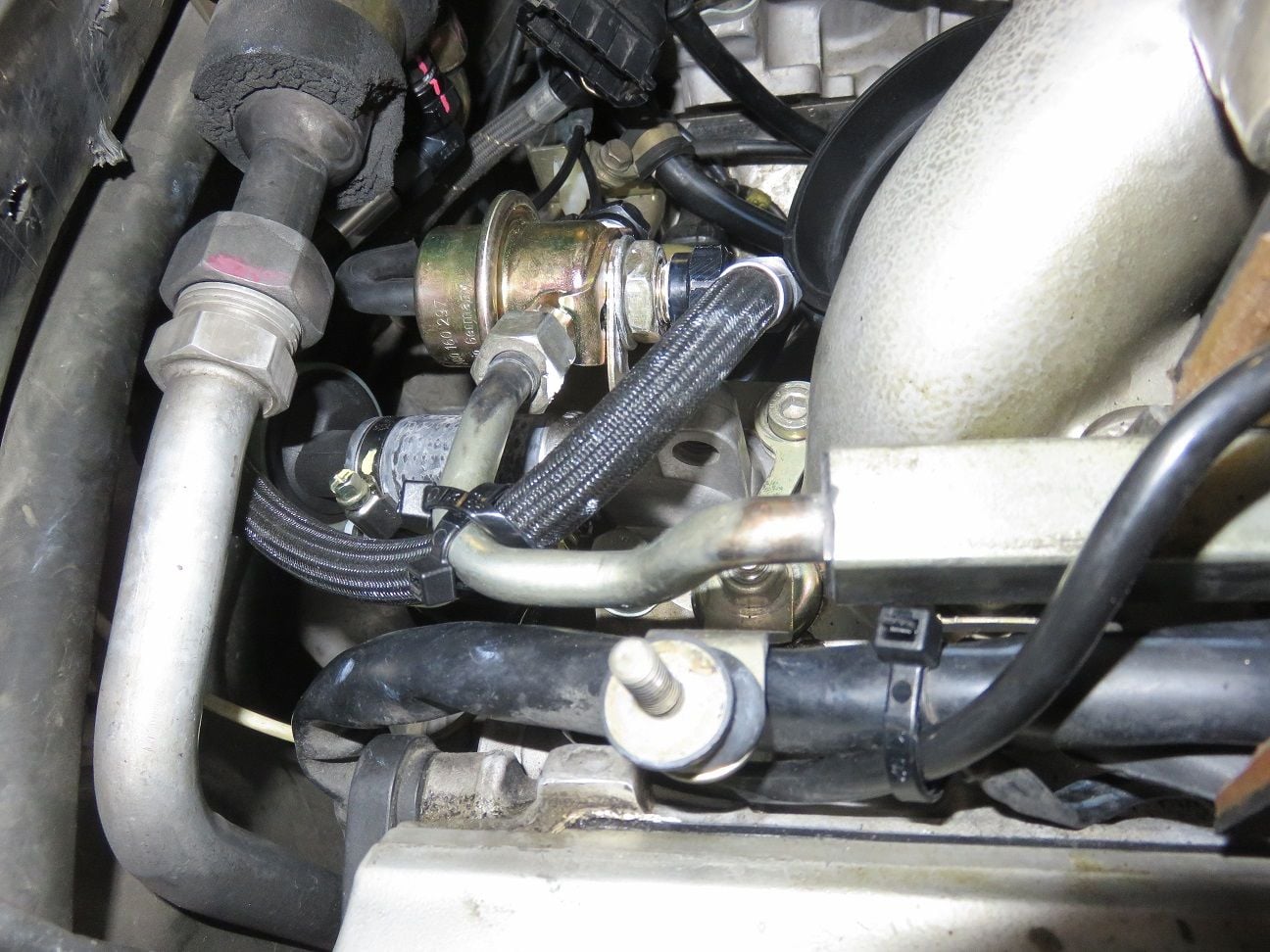
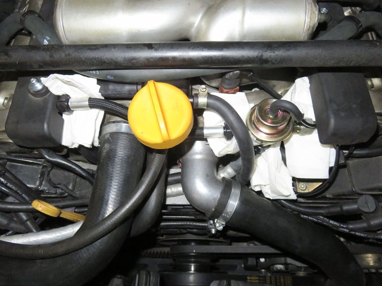
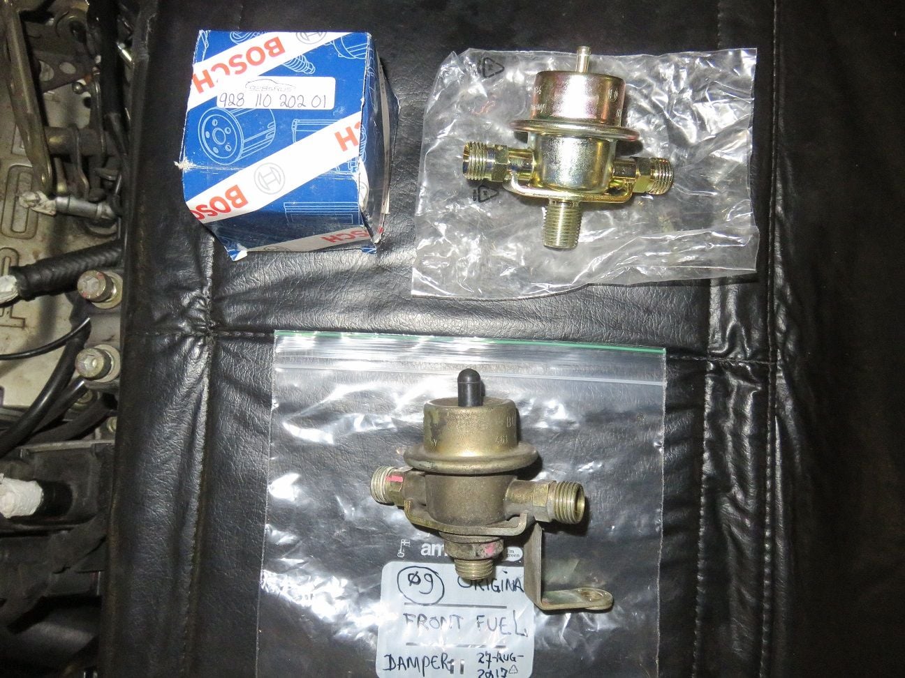
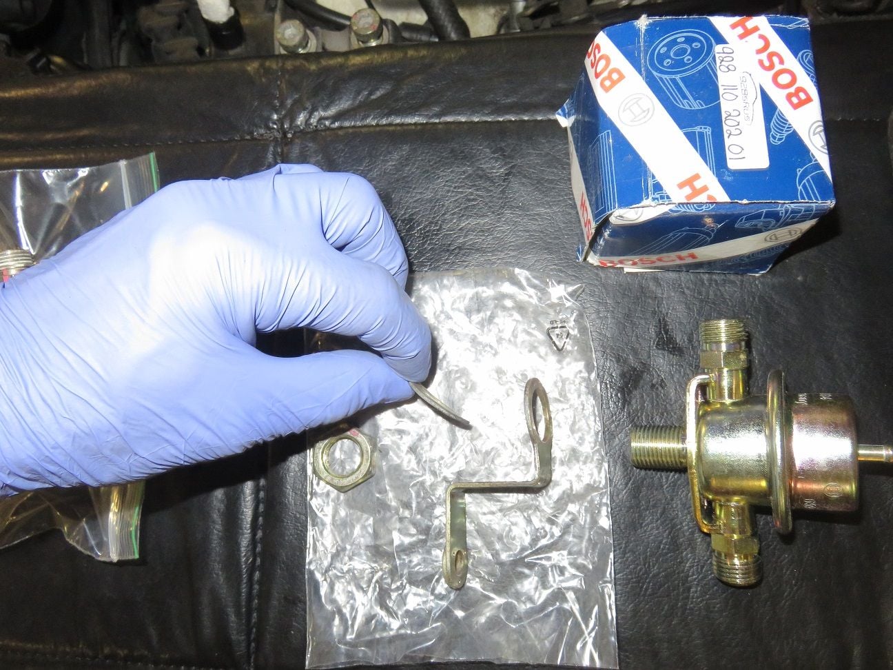
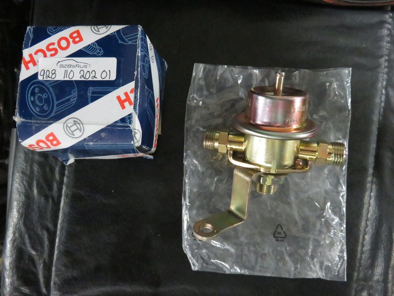
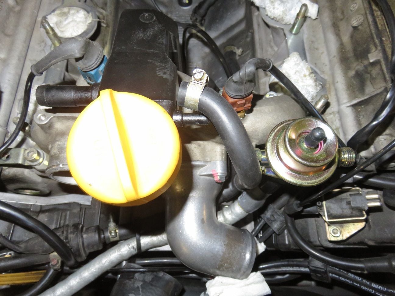
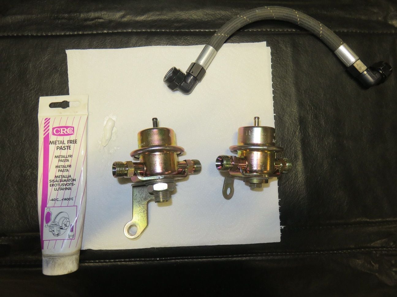
Old and new front Fuel Pressure Damper (FPD):
FPD bracket assembly taken off, with an interesting shaped/bended washer in place:
FPD bracket assembly (after cleaning) transferred to the new FPD:
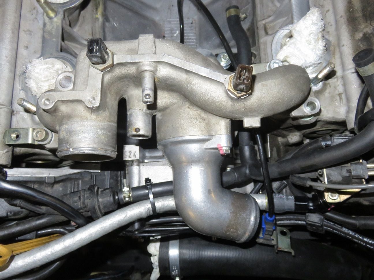
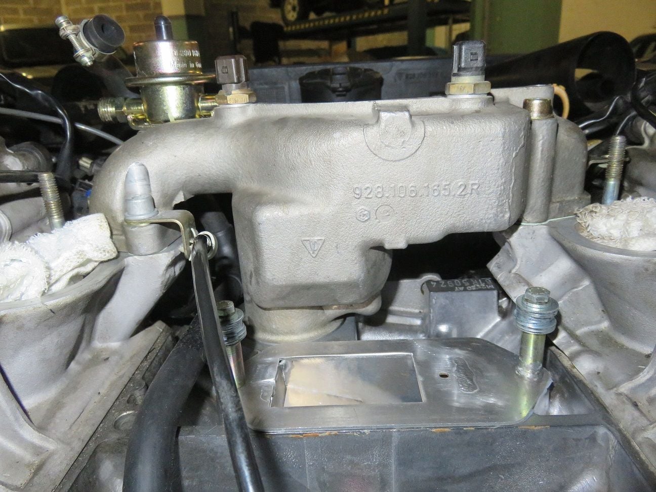
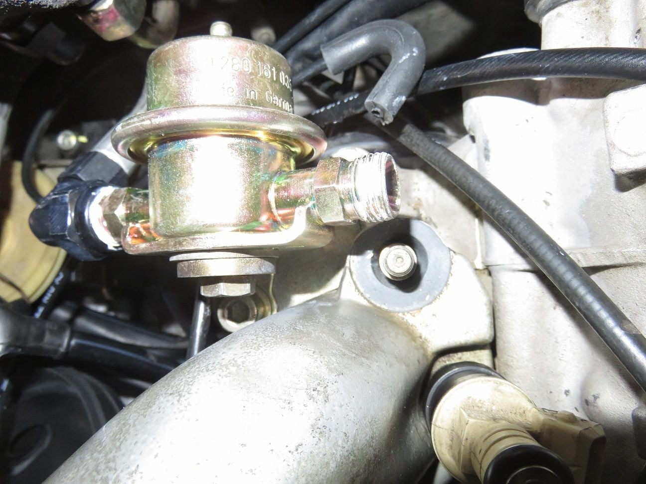
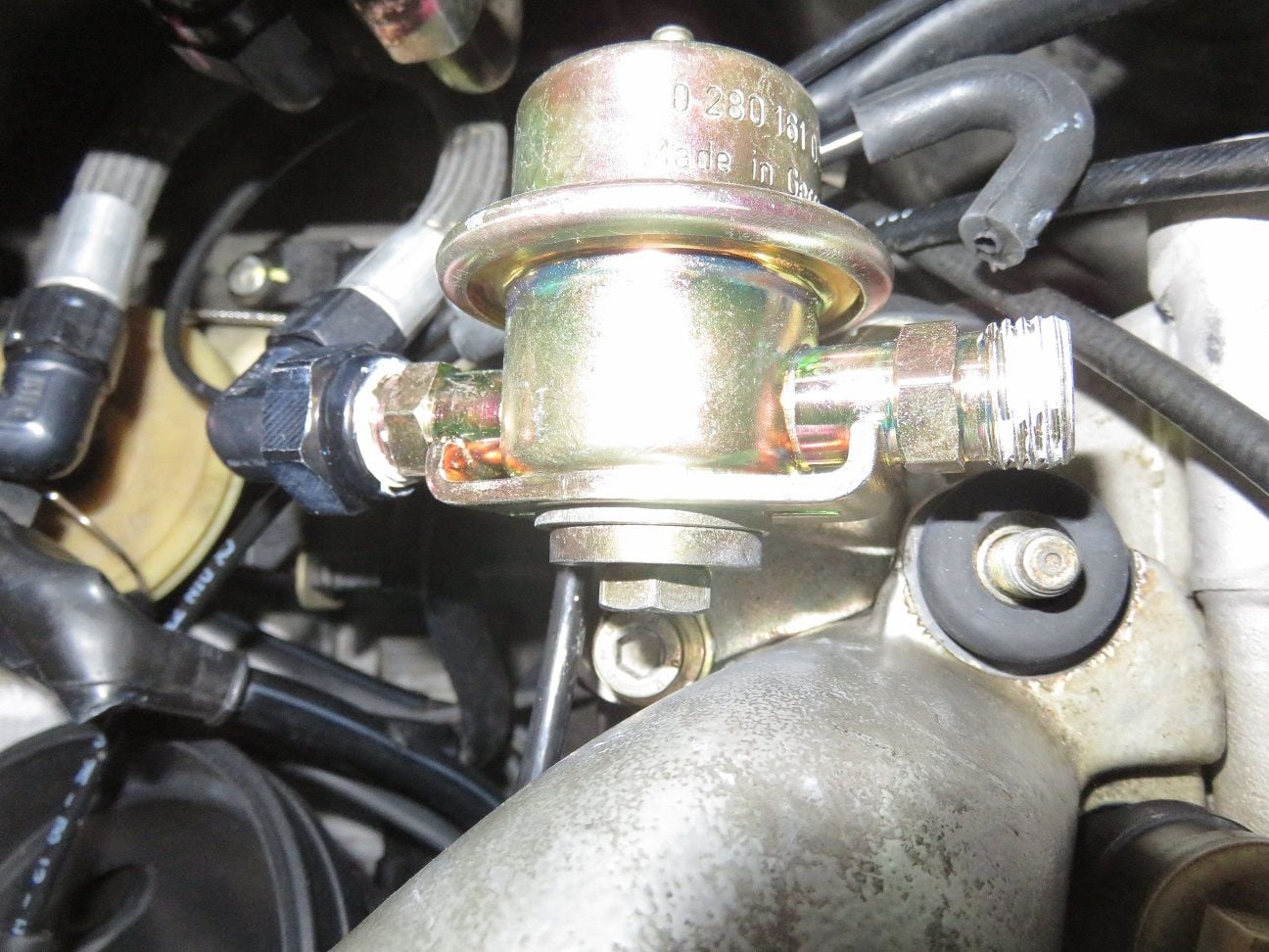
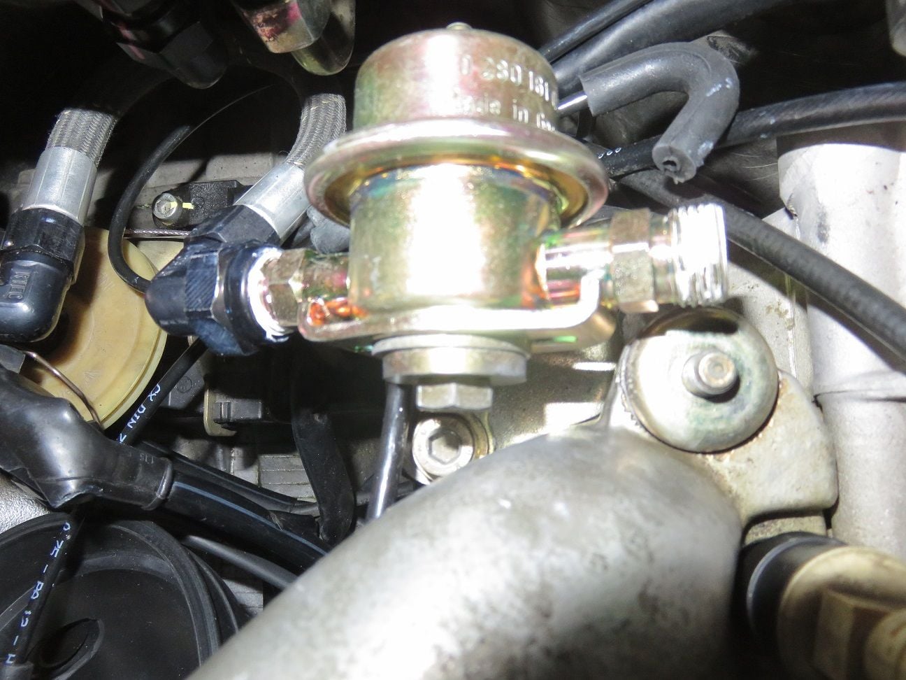
Water bridge and FPD all bolted up, and Greg Brown oil baffle Drei Bond gasket nicely cured:
Using a thin layer of Drei Bond on the oil filler neck gasket:
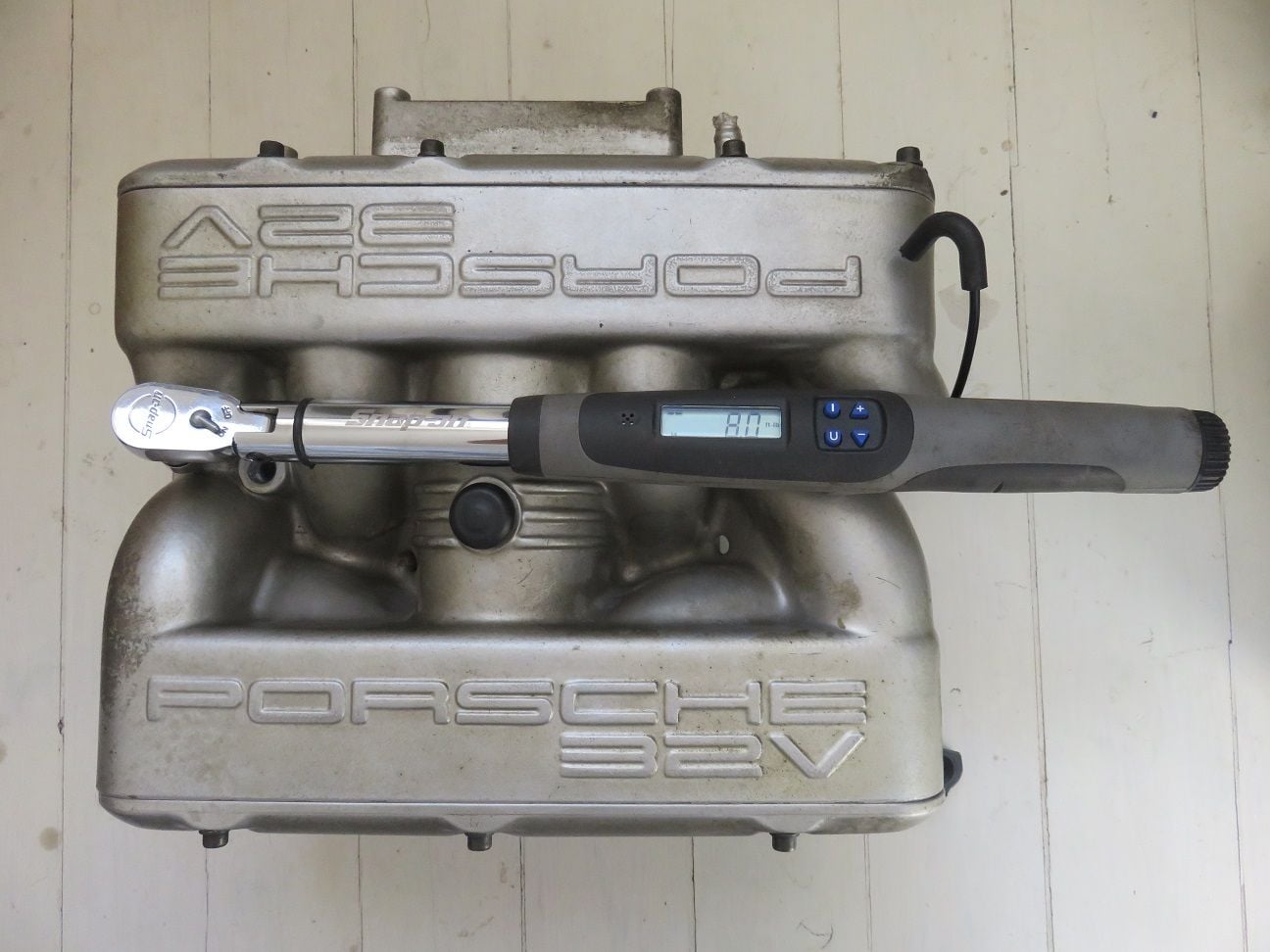
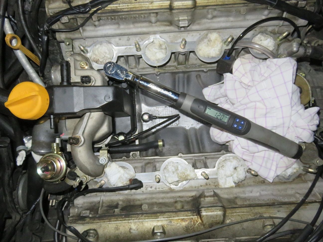
Torqueing the oil filler neck back into place, using 12Nm (being the same as I measured when removing these bolts):
Last edited by Arnoud; 07-24-2018 at 06:29 AM.
Reason: Typo's.
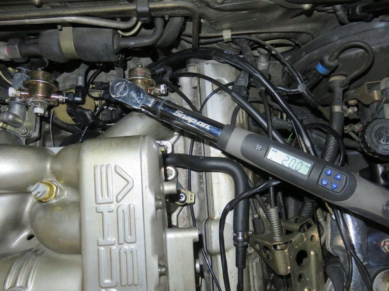
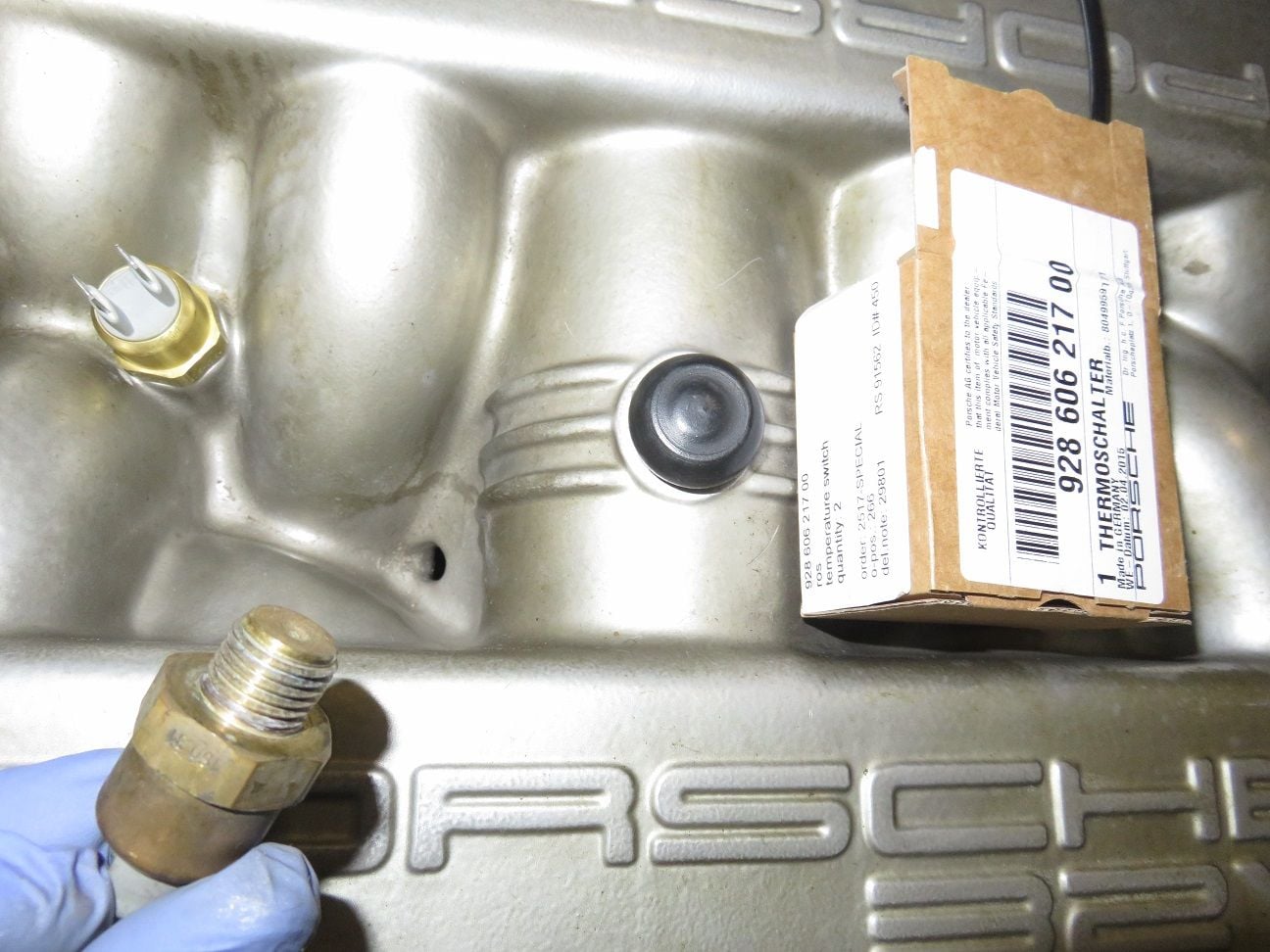
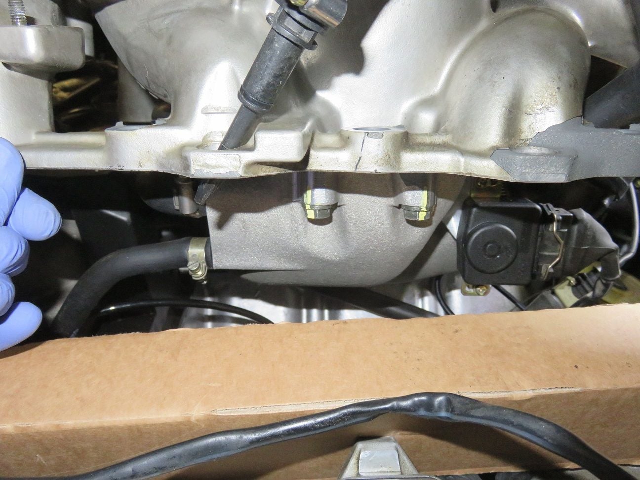
And for good measure: also replacing the intake Temp sensor (and as per Dwayne's recommendation, used 20Nm torque it down. Now notice that I forgot to put my "done" torque marking over it: that must be the reason for my remaining main problem...I wish):
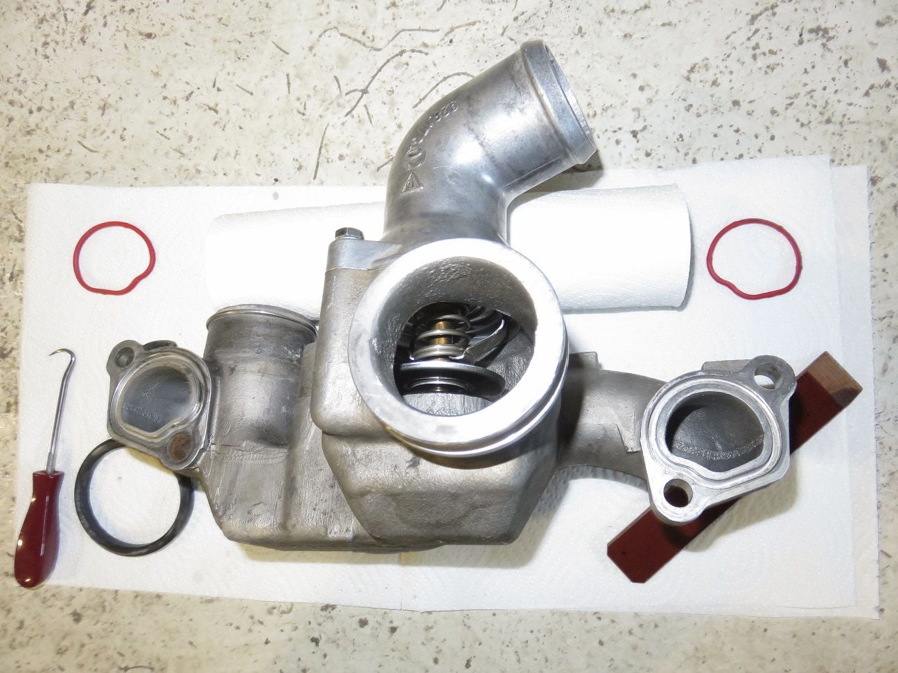
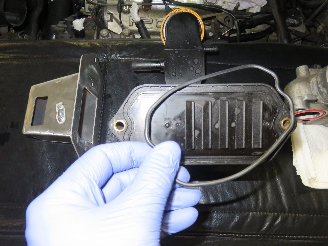
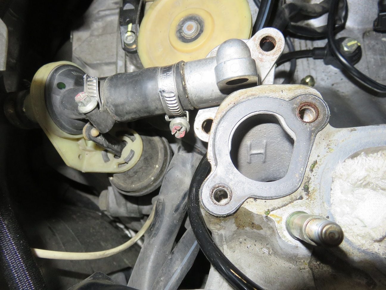
Replacing the heater circulation device + short hose, as an WYAIT task (as all that is also 24 years old, and now - with all the easy access - is a good time to replace it). Starting with taking the old seal/gasket away.
And the same on the drivers side, which only has the block-off plate there (because opened the bolts, so that gasket is "done for"):
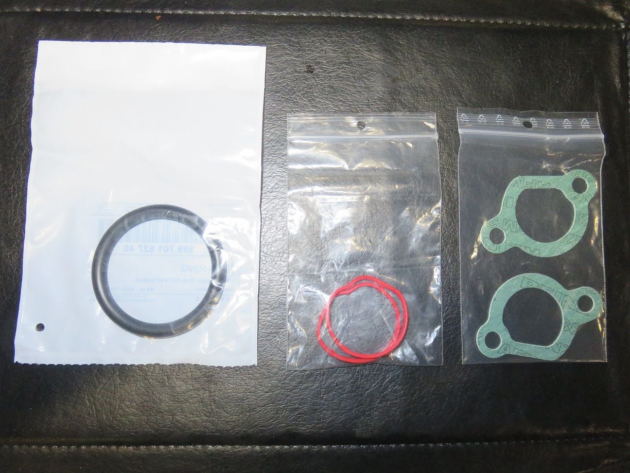
Removed the old heater circulation device + short hose, and showing the new bits next to them:
Keeping the same orientation for the new clamps:
And also renewing the vacuum elbow:
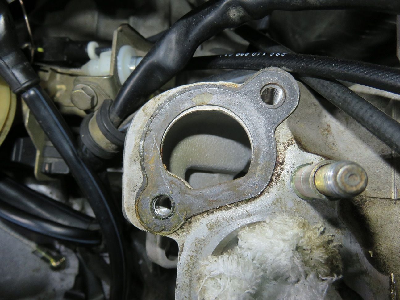
Cleaned up the surface:
And new gasket in place:
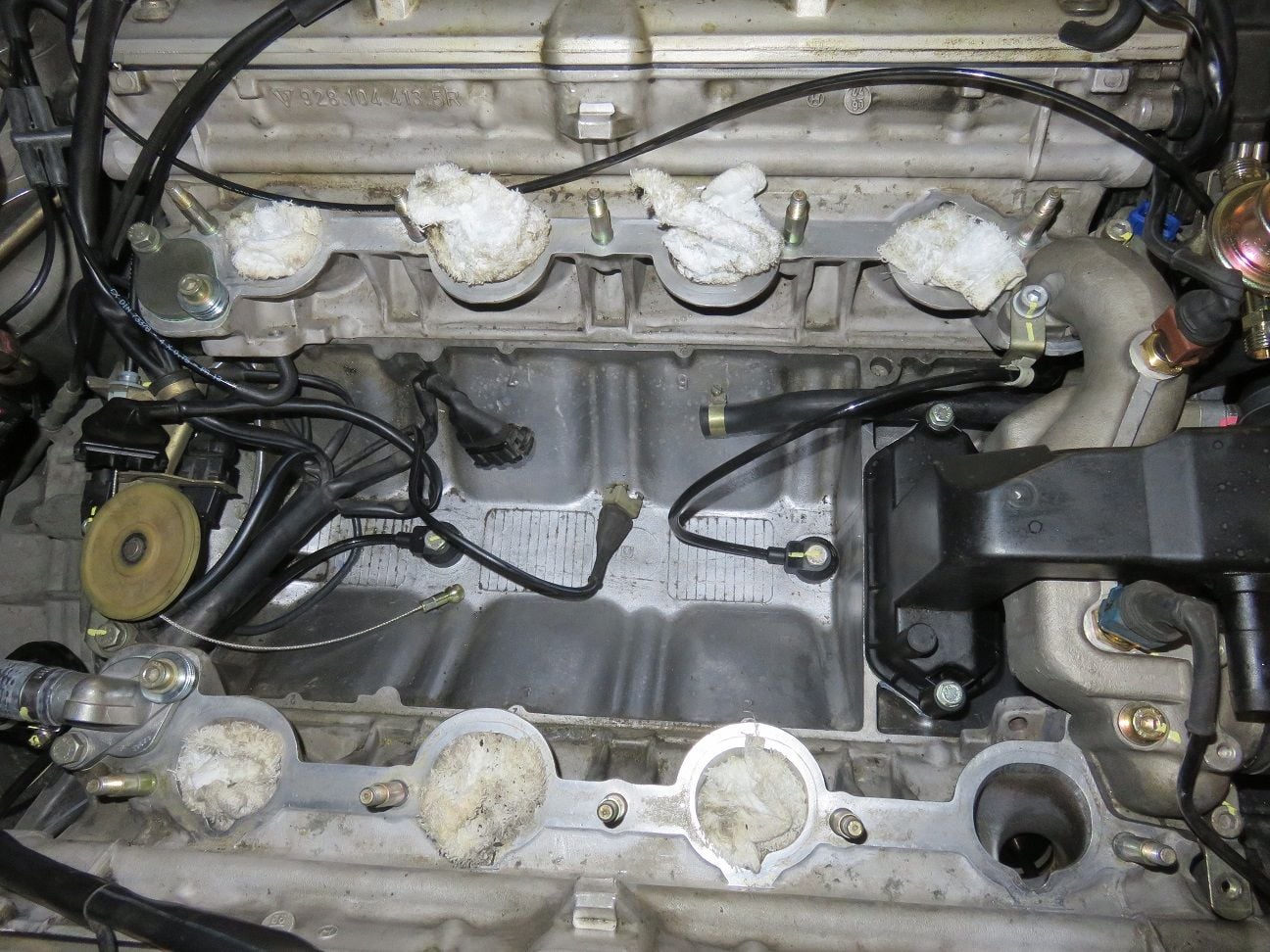
All in place, but have NOT torqued the bolts yet: as that is only to be done when the rear FPD + rear FPR have been put in place AND reconnected to the fuel rails. Started to take the rags away one by one, and then vacuum cleaned out each and every port till spotlessly clean.
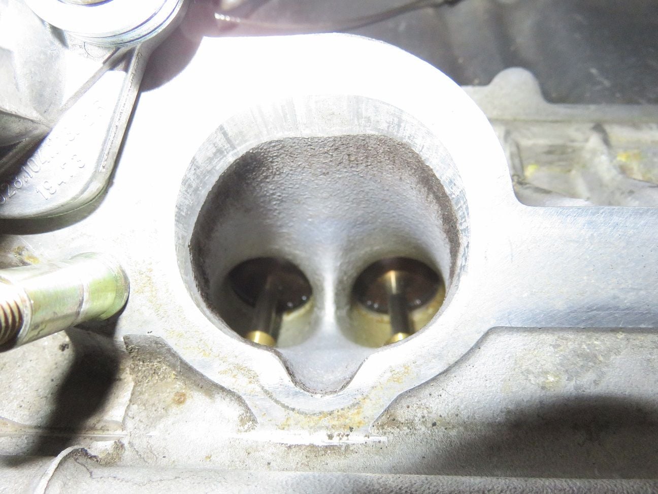
Example: intake port 4, small particles from the rag can be seen on the valves:
Improvised vacuum cleaner device for cleaning this all out: yes, that is duct-tape and a drinking straw - which worked very well for this purpose:
Intake port 4 as clean as I could get it (after which I very carefully put a paper towel in it):
Oil filler neck new hose to intake:
And put into place:
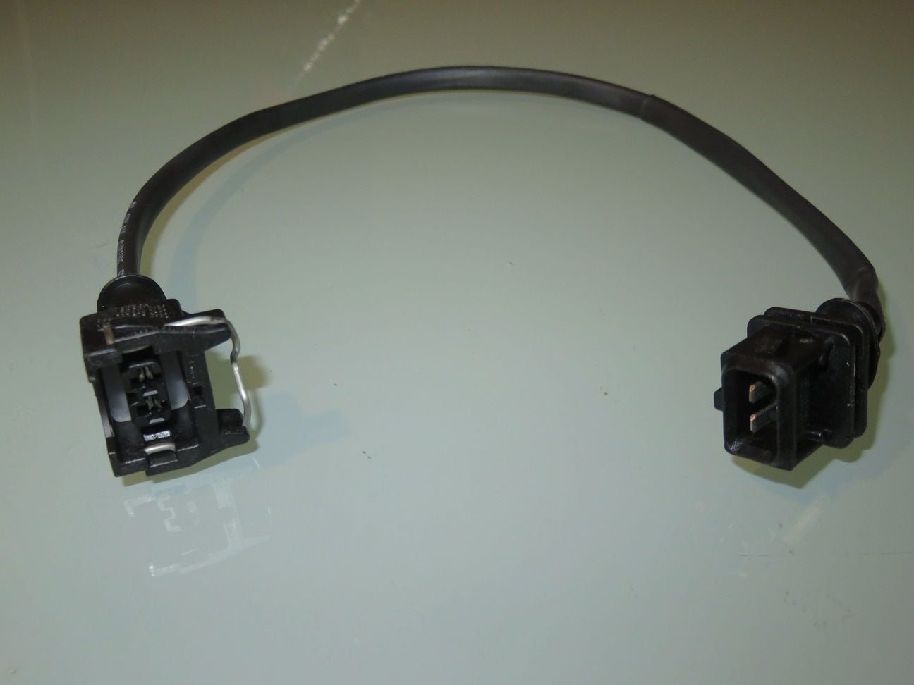
On good advice from other Rennlisters, I had build myself an 30 cm extension for the ISV electrical connector. The Bosch plugs costed me a whopping 6,82� from my local Bosch dealer, the same shop who also cleans and sells injectors (he had mine cleaned and reassembled with new filters + top- and bottom-O-rings + checked + flow tested with a detailed full printed report in 1-day: super service). The rest was just a bit of my time soldering two wires in place, and putting some shrink-wrap over it all.
For those of you who live in Finland: http://www.finjector.com/en/home/ which I had highly recommended by other local car-nuts, and now I know why myself too. Just a very happy customer here, no associations.
Extension cord put in place, and yep: I used DeOxit. Stan had me fully converted for using it on every electrical connector, some years ago (in all seriousness: thanks Stan for having made me aware of the existence of DeOxit)!
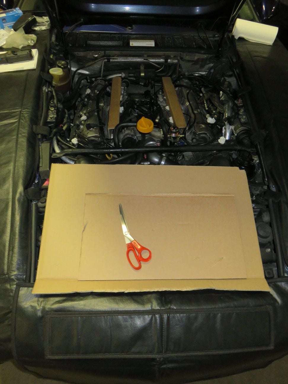
As per Dwayne's excellent guide: I made U-strips (3" by 2" by 3") from a cardboard box, as put in place here for test fitting/checking. Thanks for that tip as well, Dwayne!
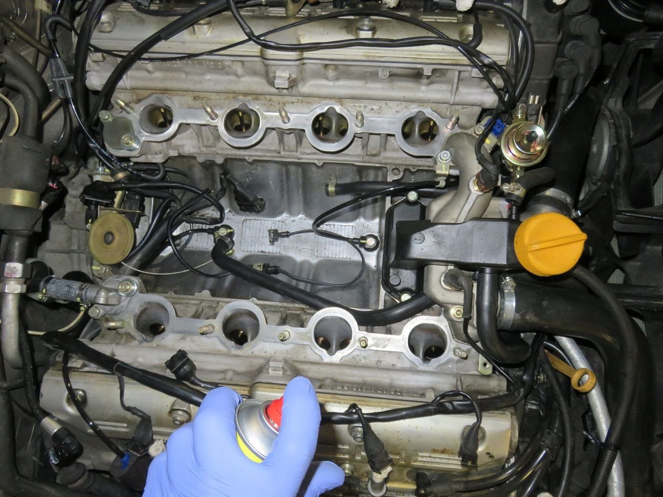
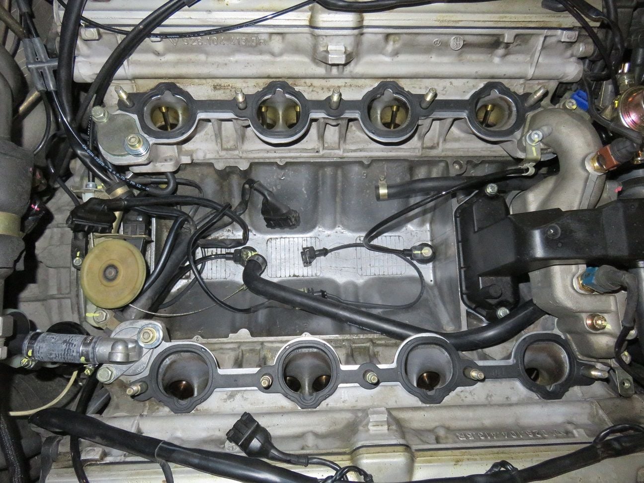
Last time cleaning of the intake port surfaces...
...and new intake ports gaskets put in place (and yes: the intake flanges are underneath them, as this is how I found them when dissembling it all - as per factory install):
Intake put on top of the cardboard U-strips:
And connecting the ISV took the whole part of 1 second now (with the extension cord in place):
3-way connector hose on the driver side connected up, as well as the TPS connector (which is a 6-pin connector on MY1994+1995, although only 5-pins used).
Bowden cable connected (I put some crease inside the ball-cup) to the throttle plate lever arm, as well as the oil filler neck hose on the right hand side Y-connector:
New fresh rubbers for the intake manifold (two old rubbers purely for reference), while re-using all the other umbrella washers and nuts after cleanup:
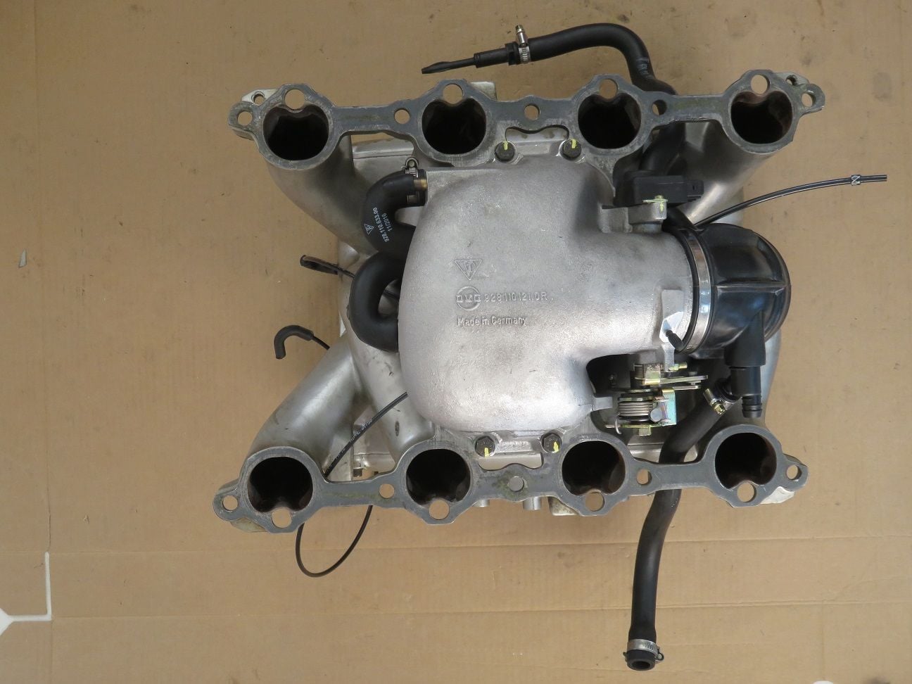
All installed, with the fuel injectors temporarily put in place for test fitting purpose (while also not having the injector holes open that way).
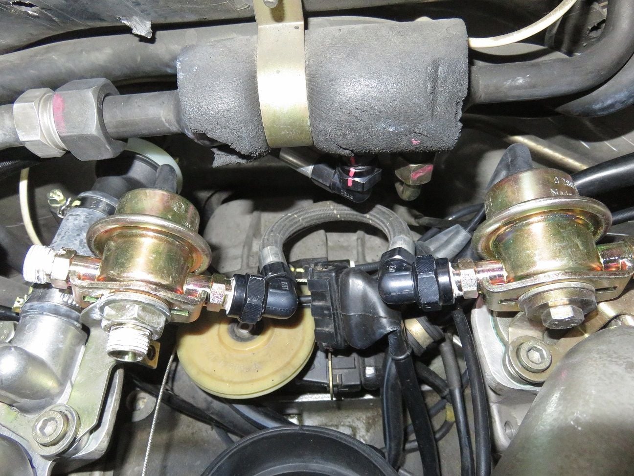
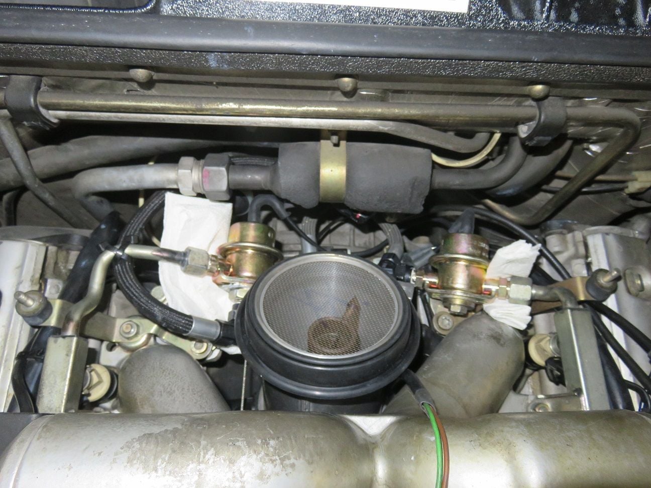
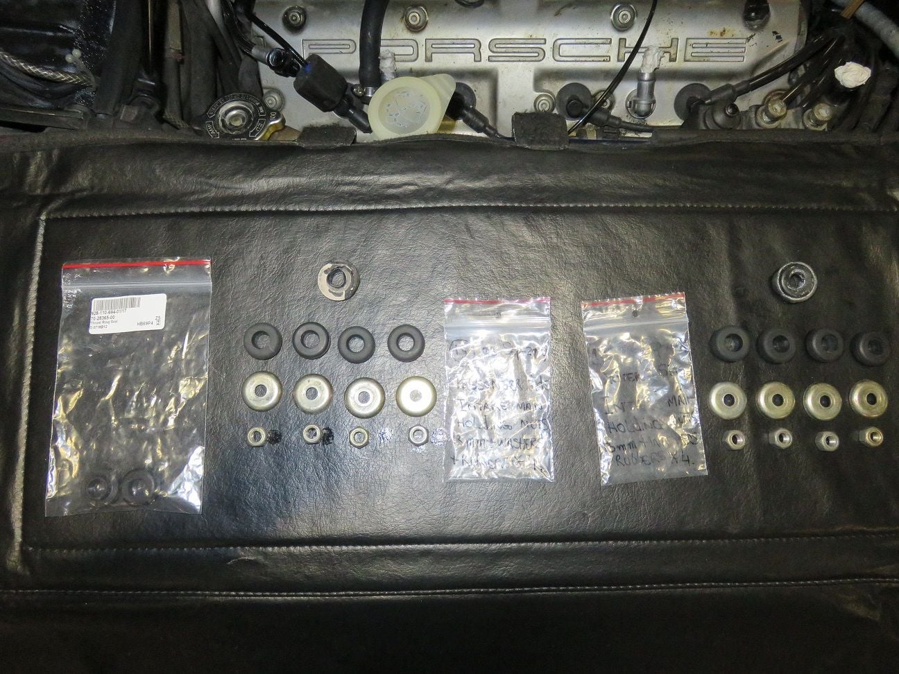
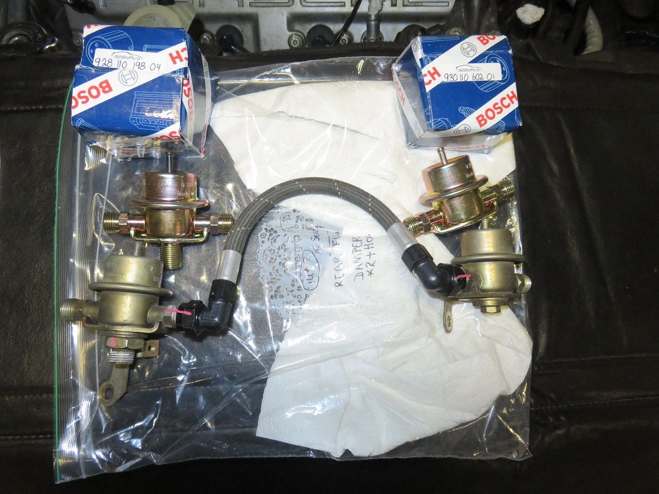
Exchanging the rear FPD + FPR combo for new ones:
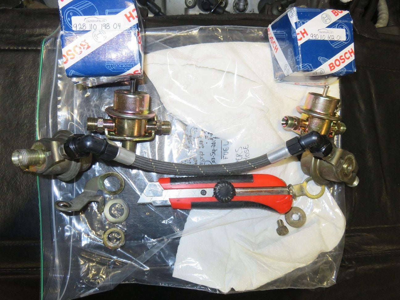
Having taken the hardware bits of the old ones. The knife I used to put a marking line on the old FPD + FPR, for where the brackets were. That way I could check on how to line up the angle of these brackets, on the new ones:
Hardware bits moved over (after cleaning):
Showing the drivers side, ready for putting on the intake manifold rubber + washers + bracket + nut onto it:
Rubber installed:
Umbrella washer installed:
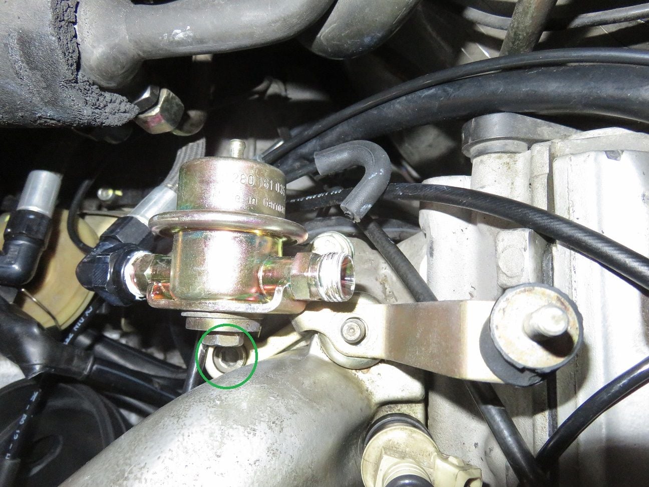
Bracket installed. Note - as per my added green circle - that it does NOT go underneath the FPR (or FPD) unit: it sits on top and around it (that is how it was installed from the factory on my car, which makes total sense). Noting such here, as initially I did do this wrong . Then I rechecked my disassembly photo's (you can never take too many photo's when doing work on our cars!), and noticed this correct order:
Nut installed (and then torqued to spec: 15Nm):
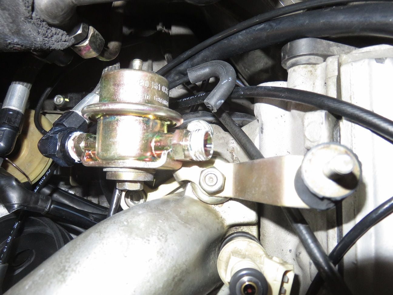
And looking like this when completed:
Last edited by Arnoud; 07-23-2018 at 09:04 PM.
Reason: Typo's.
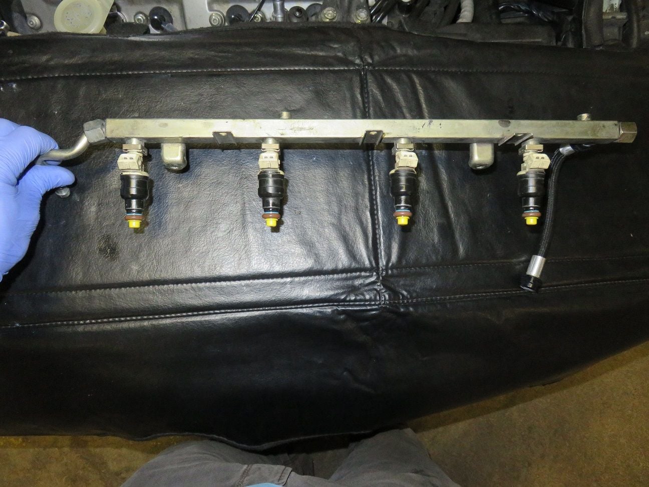
Putting the injectors into the fuel rails, and the metal clips over them:
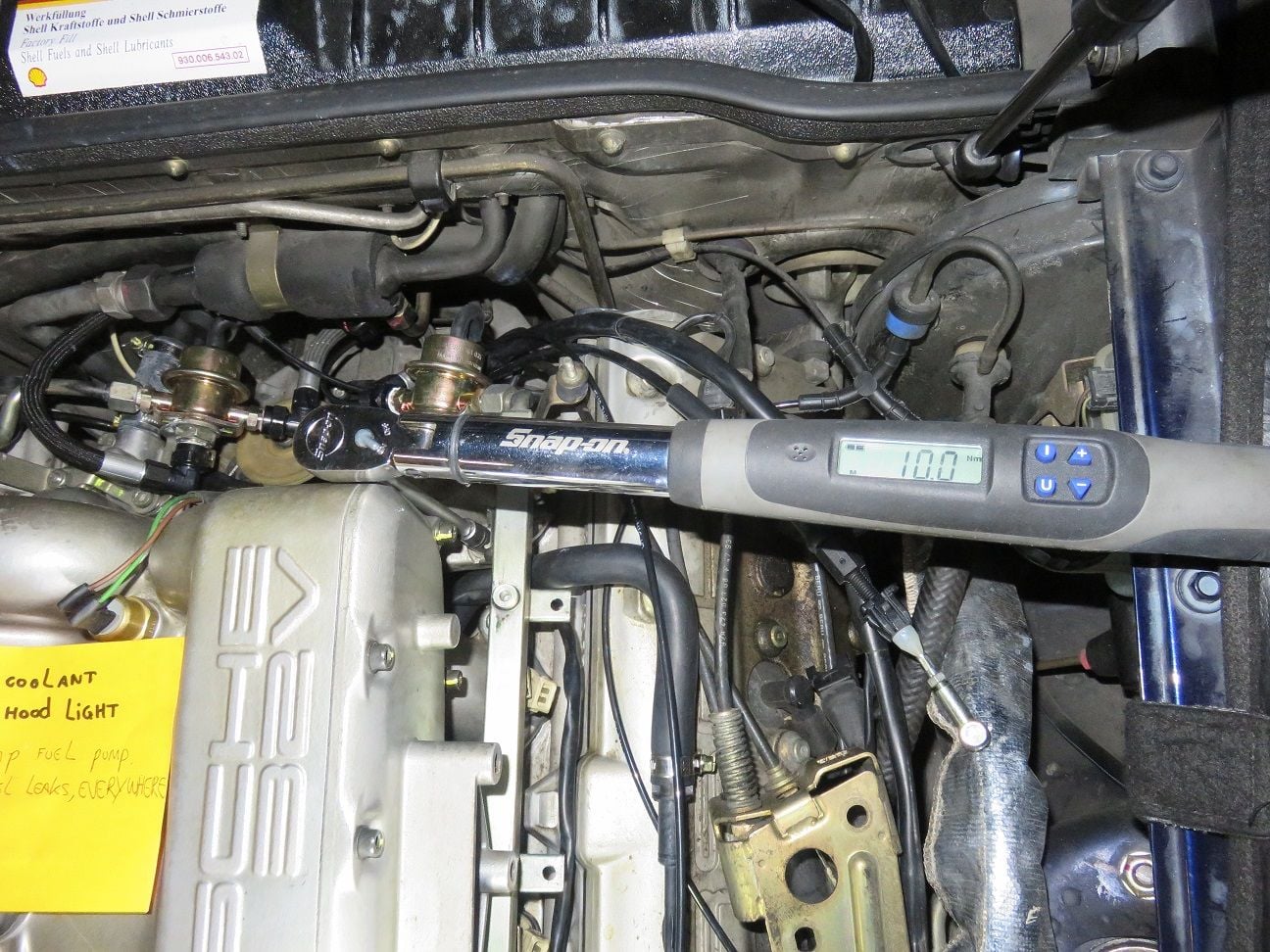
Only when all fuel rails have been perfectly alligned and connected to all other fuel line connectors, is it time to torque the fuel rail screws down (10Nm):
And only now it is time to torque down the rear coolant ports 4 bolts, as all is in the final -perfectly aligned - positions now:
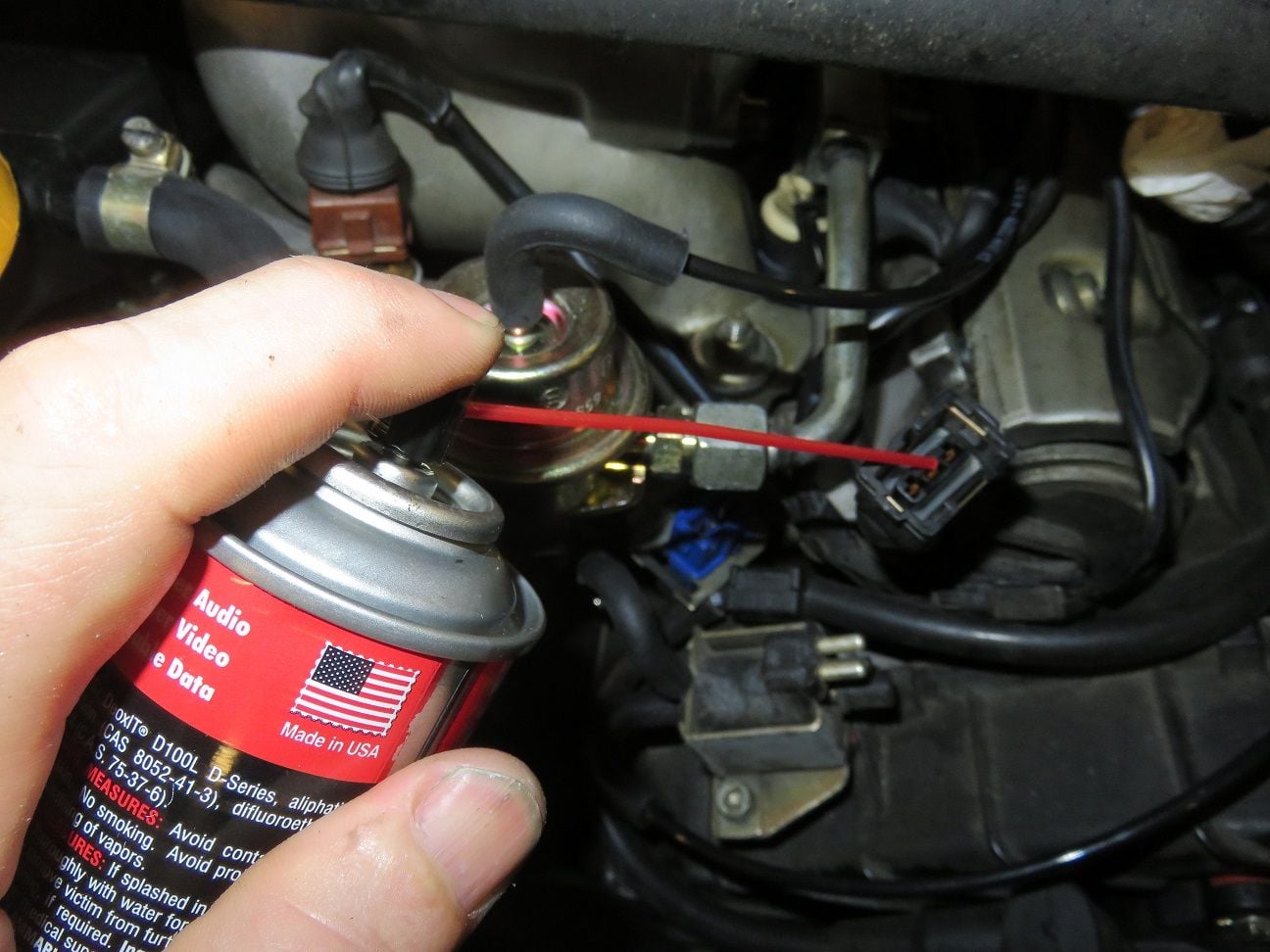
DeOxit of both knock sensors (front one shown here) + flappy solenoid (not shown):
Passenger side cables + cable ties all put into place:
And also the drivers side cables + cable ties all put into place:
And three additional - "teutonic (German/Arnoud just in case style)" - zip-ties put into place (as I used to have made before the intake refresh as well):
Passenger side fuel rail cover put into place:
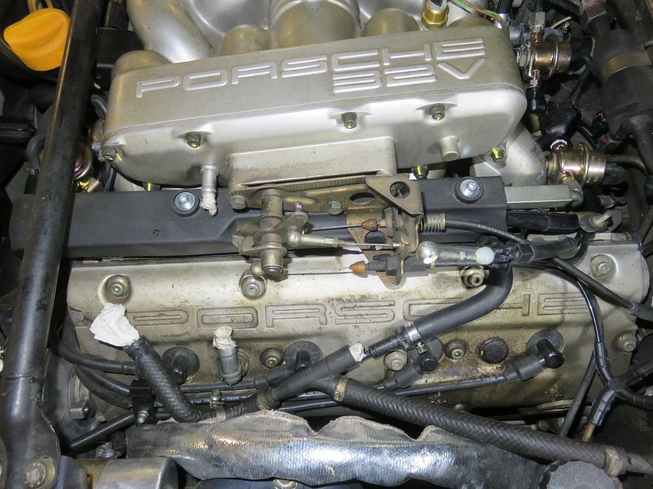
Throttle quadrant put into place. Also tuned the Bowden cable (by turning the Bowden cable offset piece a few times with a 13mm wrench): so only when opening the throttle for a little bit can the TPS idle contact be heard clicking open
Balancing tube/hose + clips renewal:
New balancing tube/hose installed:
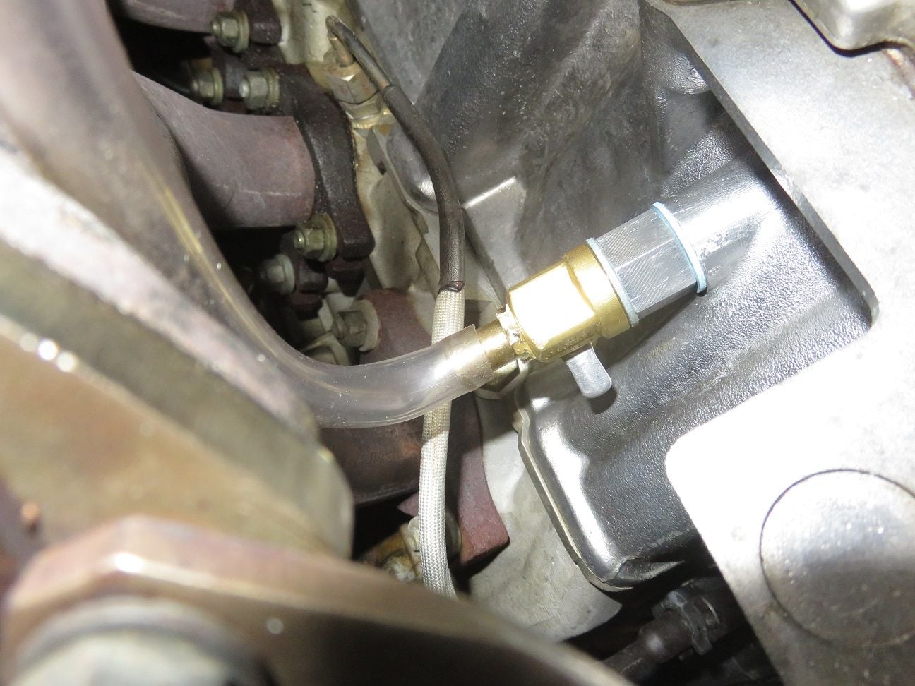
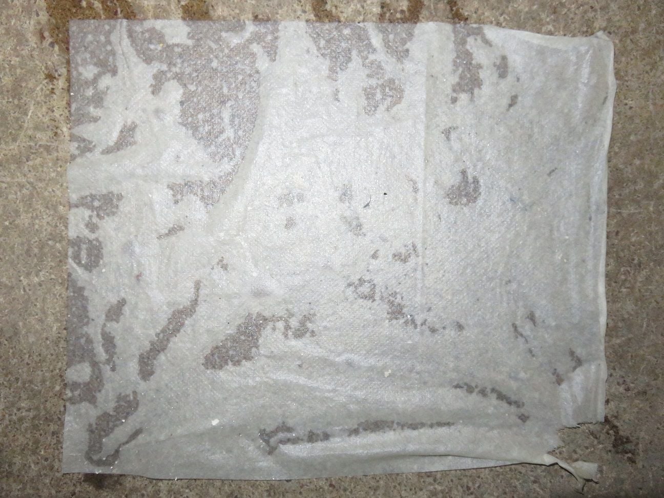
Putting paper towels underneath all fuel connections at the rear, for fuel leak test:
And dito for the front:
Fuel leakage test did not show any leaks on the paper towels, however I could smell a very small hint of fuel from the front driver side fuel rail connector - so tightened that a bit more. After that: all was very fine.
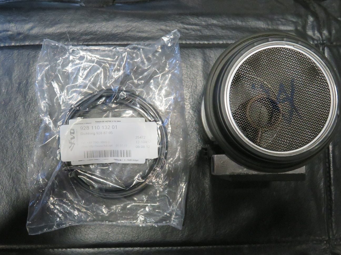
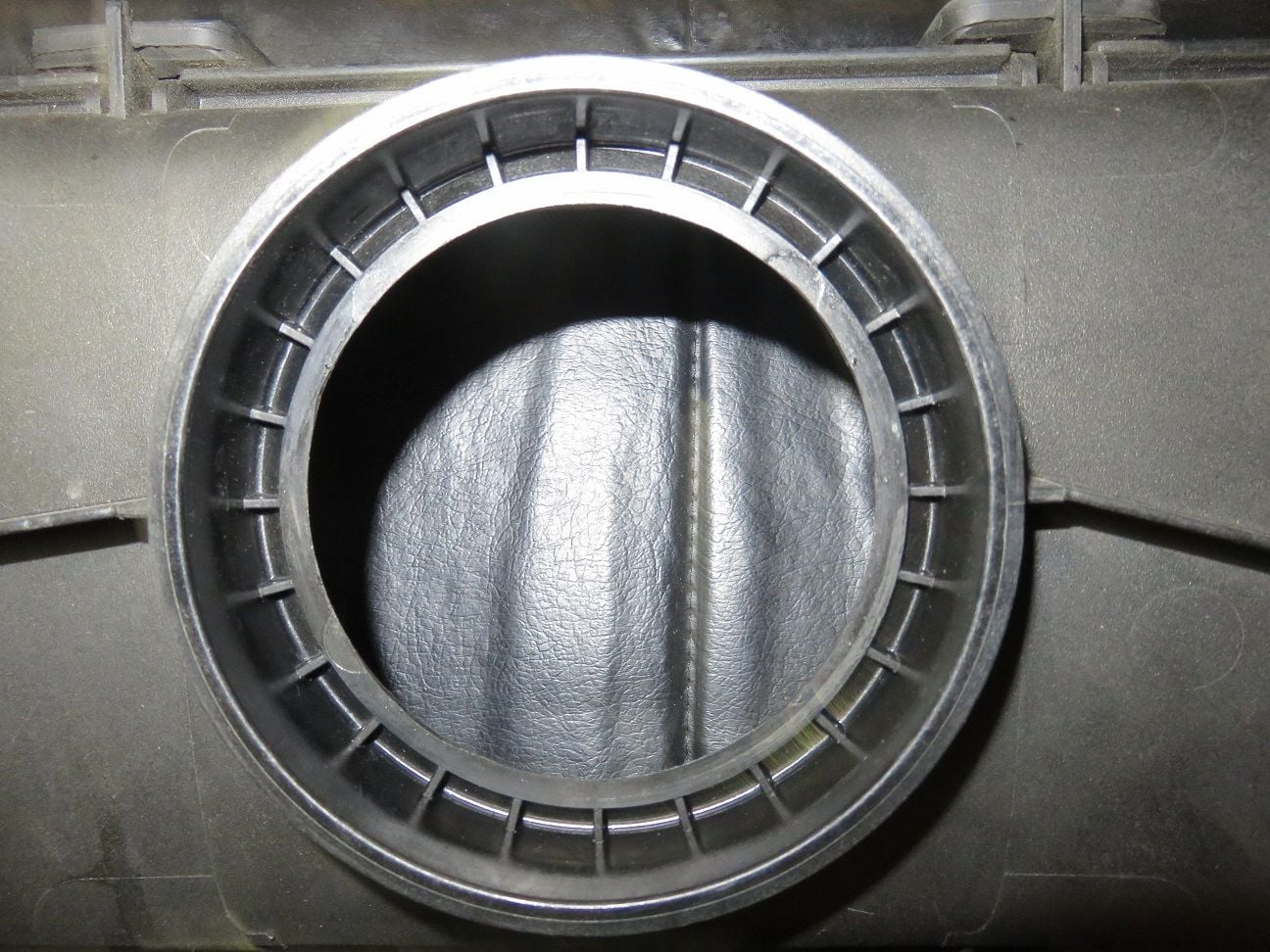
New MAF to airbox rubber to be used too. Nothing to much wrong with the old one, but heeee...replacing everything...
Initially I installed this the incorrect way, by putting it onto the MAF first. Don't do that: instead put it onto the airbox, so that the edge of the rubber you fold over the airbox inner plastic lip - as shown here (thanks for Erkka for pointing out this "titbit" of knowledge):
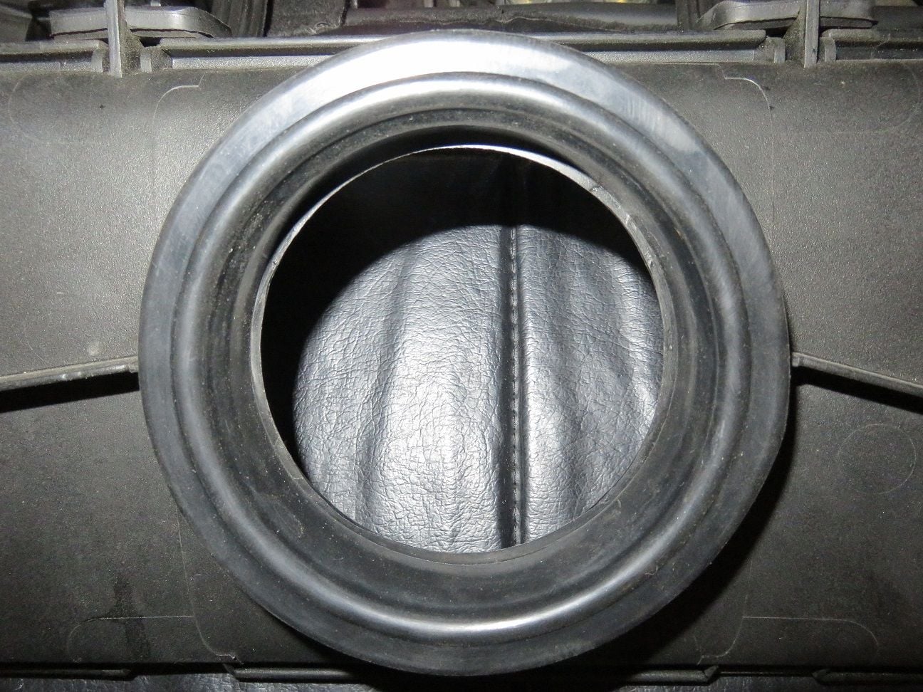
And properly installed, as it should be, like this:
And then pushed onto the MAF, and get an as good as seal as possible:
.
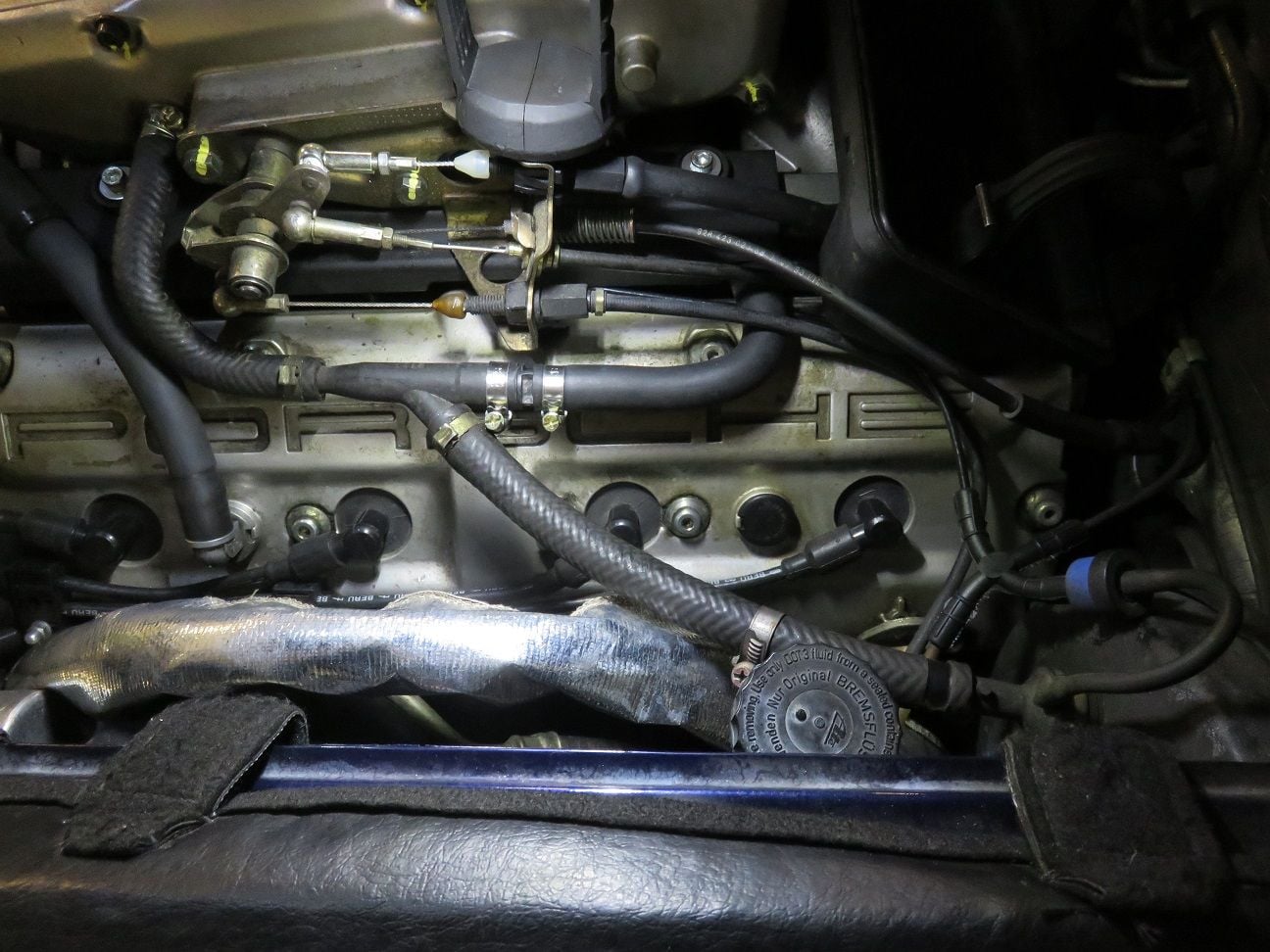
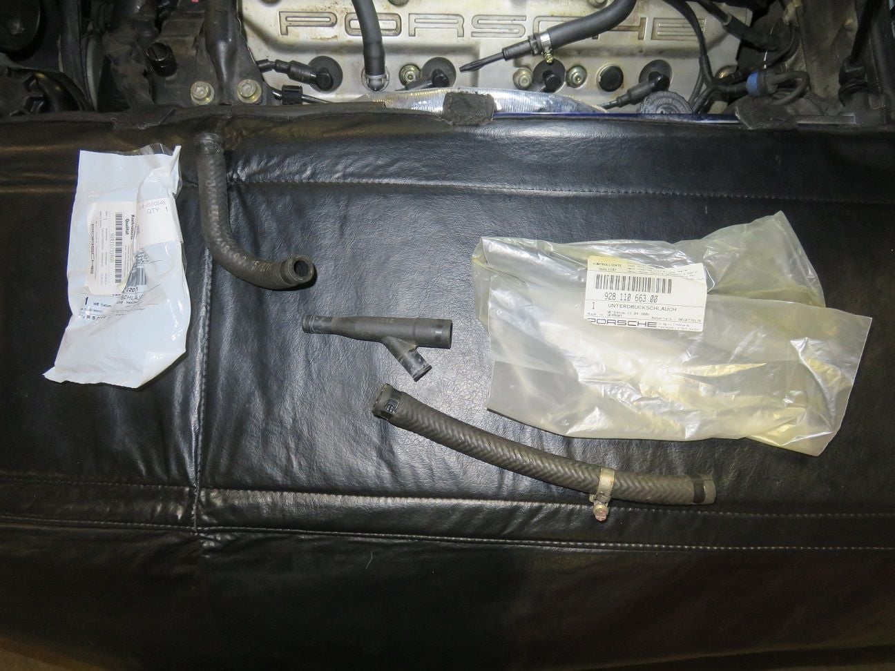
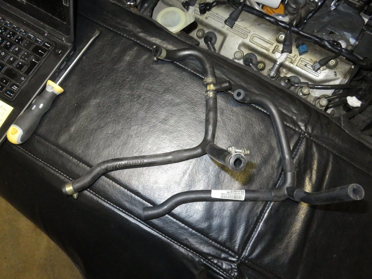
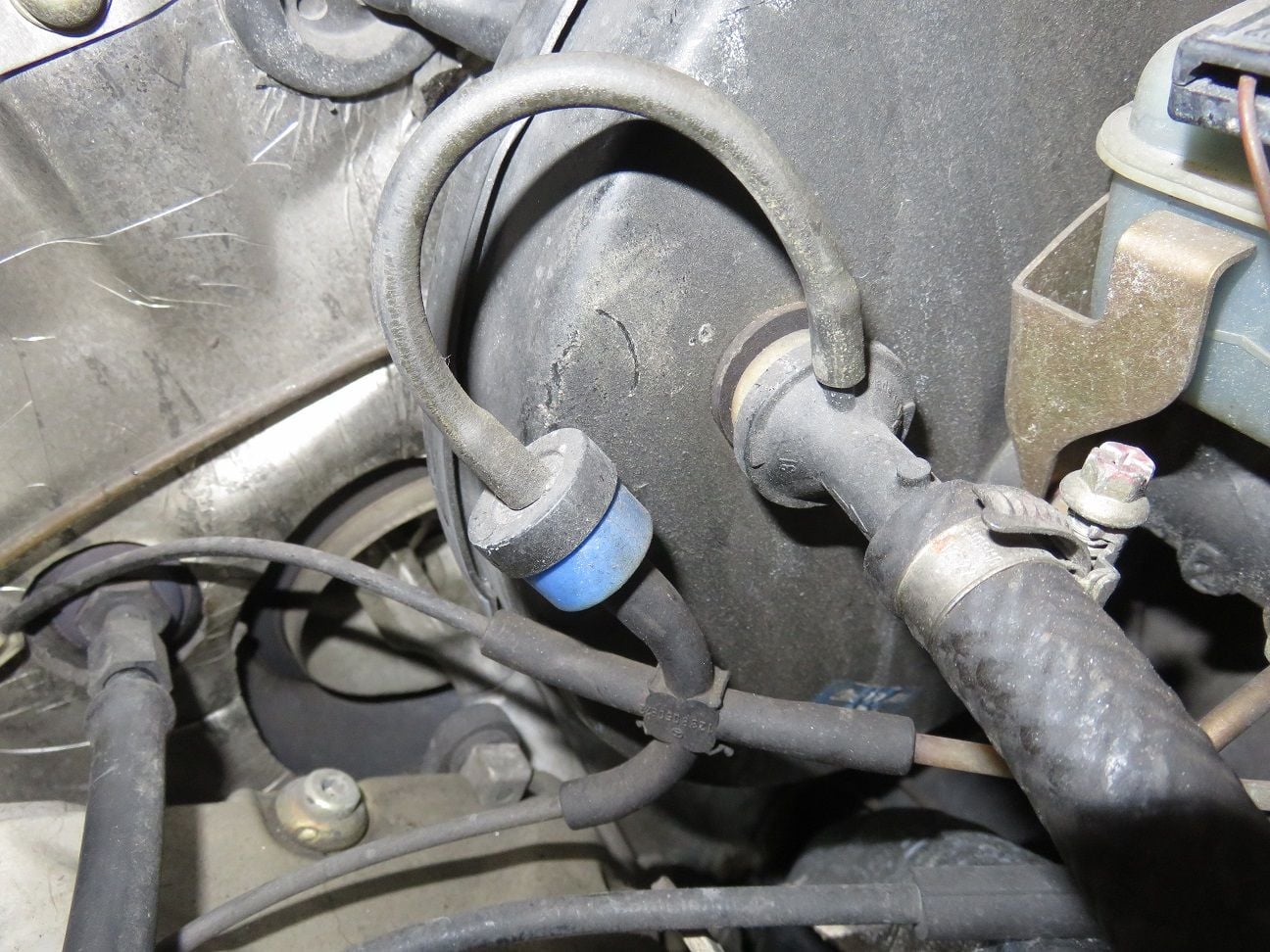
Last two remaining old hoses to swap out: venturi to intake and venturi to brake booster
Old and new hoses...
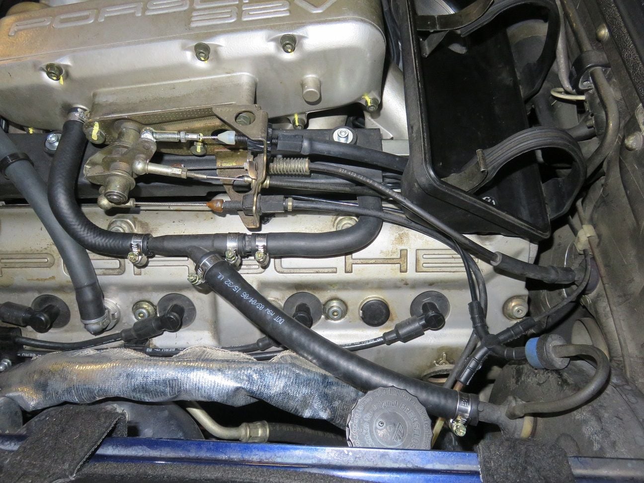
And the last two new hoses in place:
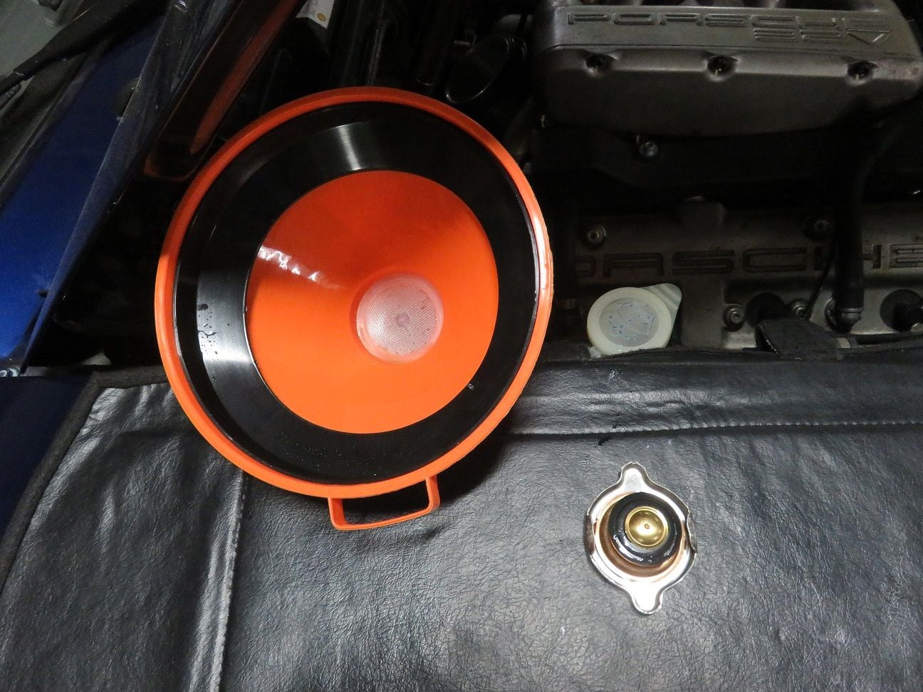
Not forgetting filling up the coolant: ended up with a total of 4 (as put in earlier) + 10 = 14 liters of coolant topped up:
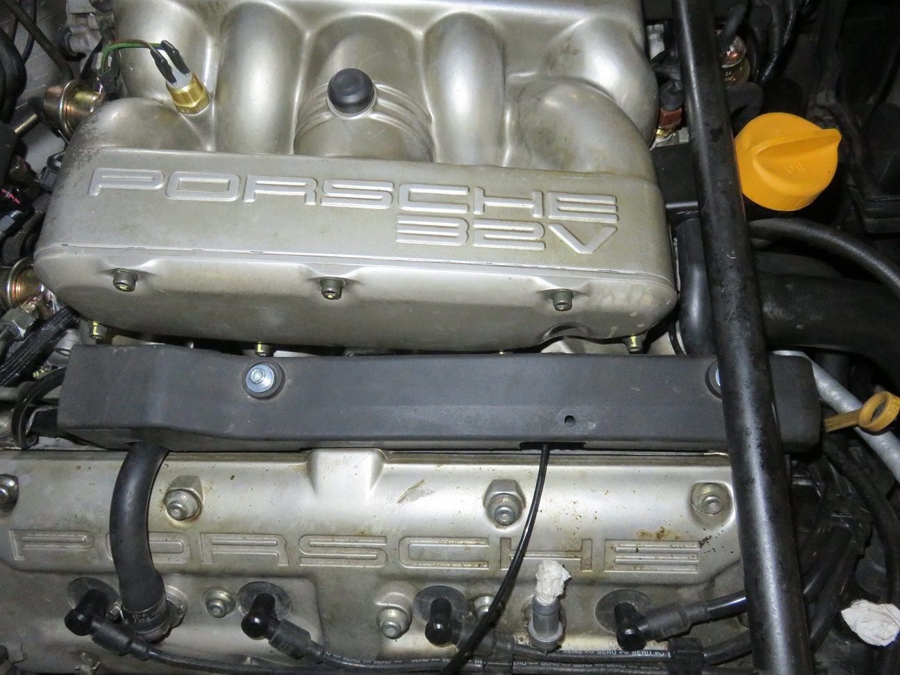
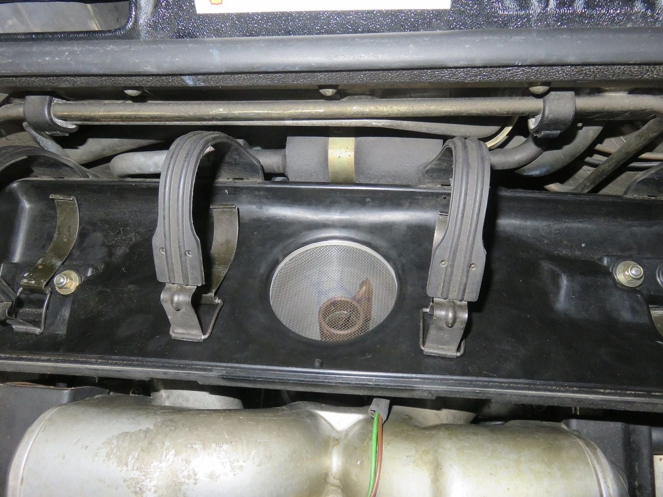
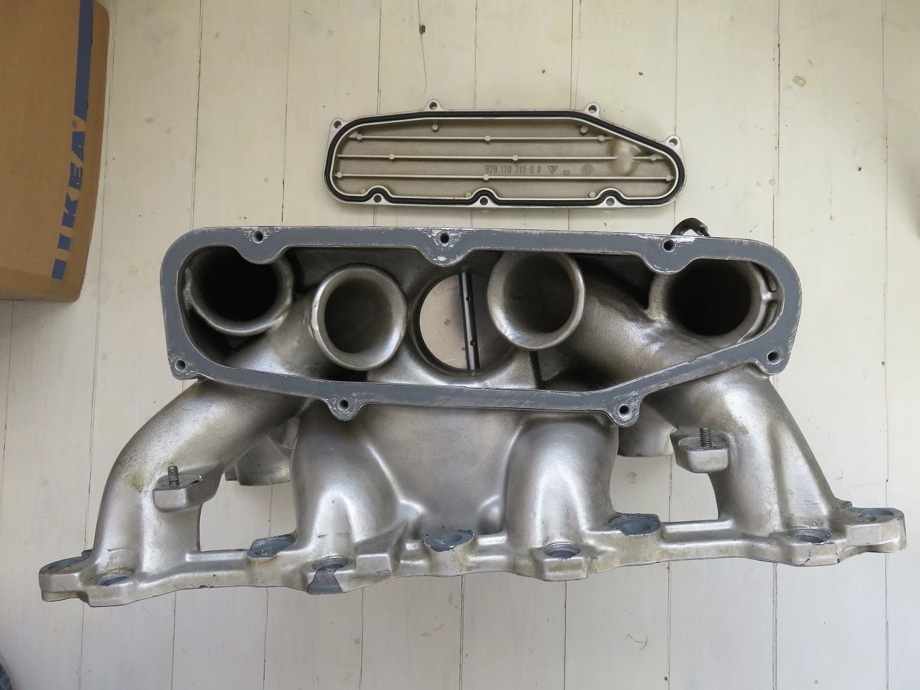
And the finishing touch: new rubber too for the intake flappy cover:

 06-11-2018, 05:54 PM


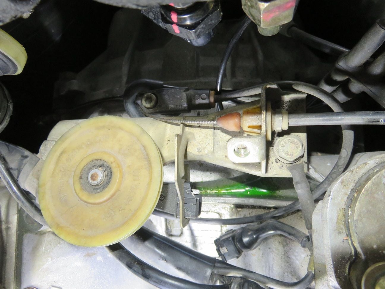


 . Then I rechecked my disassembly photo's (you can never take too many photo's when doing work on our cars!), and noticed this correct order: